Transcription
Page 1 of 16 Exploring XBees and XCTUIntroductionIs your project being dragged down by wires? Looking for an easy transitionto wireless communication? If you want reliable, low-cost, bi-directionalcommunication at moderate speeds XBee may be the solution for you!XBees are hugely popular wireless transceivers for a number of reasons.They’re flexible – they send and receive data over a serial port, whichmeans they’re compatible with both computers and microcontrollers (likeArduino). And they’re highly configurable – you can have meshednetworks with dozens of XBees, or just a pair swapping data. You can usethem to remotely control your robot, or arrange them all over your house tomonitor temperatures or lighting conditions in every room.Covered In This TutorialThe pair of XBees alone won’t get you very far. In most cases you’ll want aseparate module to interface with the XBee. You can use an XBee Shield toconnect an XBee to your Arduino. Or you can use an XBee Explorer toconnect an XBee to your computer.The focus of this tutorial is to explain how to use an XBee Explorer with anXBee. There are a variety of Explorer boards, all designed to achieve thesame purpose: to create a communication gateway between your computerand the XBee.
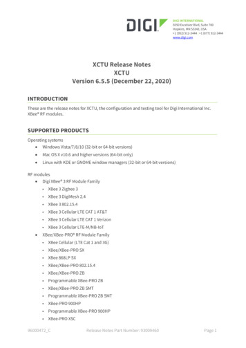
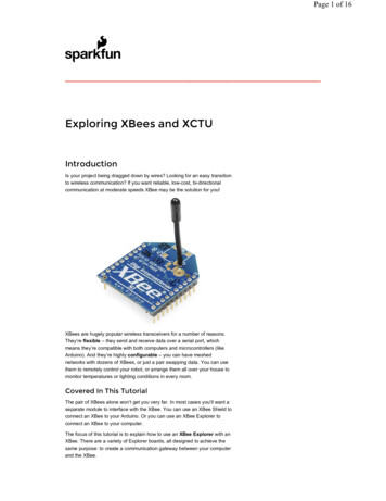
Page 2 of 16The Explorers: USB Explorer, Explorer Dongle, and Serial Explorer.With an XBee Explorer connected between your computer and your XBee,and with the help of the X-CTU software, you can easily configure XBees,test connections, and pass data between your computer and remoteXBees. We’re going to show you how to do all of that in this tutorial!Materials RequiredXBees are really only useful if you have at least a pair of them. They needbuddies to talk to! Hence, there’s a lot of “2x” in this list of materials: 2x XBees – XBees exist in a variety of series, frequencies, andranges. If you’re just getting started with XBee, we highlyrecommend going with Series 1 models – either with a traceantenna, wire antenna or u.fl connector. For more help picking an XBee, check out our XBee BuyingGuide. 2x Explorers – either the Explorer USB, Explorer USB Dongle, orExplorer Serial. These boards act as an interface between your computer andan XBee. They’re used to configure your XBee and pass datato and from your computer. Depending on which explorer you have, you may also need amatching mini-B USB or serial cables. At least one computer with X-CTU installed. The latest version of X-CTU is available for both Mac andWindows!Suggested ReadingThis tutorial builds on some lower-level electronics concepts. If you’re notfamiliar with the subjects below, we recommend checking out thosetutorials first. Serial Communication – XBee’s communicate over a serial port. Thistutorial will get you familiar with terms like “RX”, “TX”, “baud rates”,“stop bits”, and “parity”. Serial Terminal Basics – The X-CTU software we’ll use has anintegrated serial terminal called the “console”. You can use yourpreferred terminal instead; if you don’t have a preferred serialterminal, check out this tutorial. XBee Buying Guide – We highly recommend Series 1 XBee’s, if thisis your first time playing with them. If you’re curious about other XBeeclasses, check out this guide! Hexadecimal – XBee configuration settings – like addresses andnetwork ID’s – are all programmed in hex. Base 16. If you don’t knowhow to make numbers with 0-9 and A-F, check out this tutorial.Selecting an ExplorerThe first step to communicating with your XBee is picking an interfaceboard that allows you to. XBee Explorers act as a gateway between yourcomputer and your XBee. There are a few to pick from, each offering theirown, key differences. Here’s a quick overview of each:XBee Explorer USB
Page 3 of 16The XBee Explorer USB is the most popular of the Explorers. It’s equippedwith a mini-B USB connector, so you’ll need the proper USB cable toconnect it to your computer.The highlight of this board is an FT231X USB-to-Serial converter. That’swhat translates data between your computer and the XBee. There’s also areset button, and a voltage regulator to supply the XBee with plenty ofpower. In addition, there are four LEDs that’ll help if you ever need to debugyour XBee: RX, TX, RSSI (signal-strength indicator), and a power indicator.This board also breaks out each of the XBee’s I/O pins to a pair ofbreadboard-compatible headers. So if you want to make use of the XBee’sextended functionality, you can solder some header pins into those, or evenjust solder some wire.XBee Explorer USB DongleThe XBee Explorer Dongle is an extension of the Explorer. In fact, the onlyreal difference between this and its predecessor is the USB connector. TheDongle can be connected directly to your laptop or PC USB port.Or, if you need some distance from your computer, you can use a USBextension cable.The Dongle still shares all of the features of its sibling – reset button, LEDs,voltage regulator, and breadboard-compatible pin breakouts.XBee Explorer SerialComputers with an RS-232 serial port are becoming harder and harder tofind, but if you do have one of those relics, the XBee Explorer Serial is aviable option.
Page 4 of 16The Serial Explorer has a bigger footprint than its USB-based brethren, butstill shares most of the same features. There are RX and TX LEDs, resetbutton, break-out pins, and a voltage regulator.The Serial Explorer does require an external power supply. It’s got a barreljack connector which will work with either our 9V or 5V wall adapters.If you’re using an Arduino, another option available is the XBee Shield.That’s a subject for another tutorial.Drivers and AssemblyThe USB-based XBee Explorers all operate using an FTDI FT231X chip,which converts serial to USB and vice-versa. This is one of our favoritechips because it supports all computer platforms and it’s easy to work with.If this is the first FTDI chip you’ve ever connected to your computer (itprobably won’t be your last), there is some driver installation to get out ofthe way.We’ve written a tutorial detailing How to Install FTDI Drivers tutorial. So goahead and plug your USB Explorer into your computer, and head on toeither the Windows, Mac, or Linux section there. (Ignore the final steps,where Arduino software is invoked.)Regardless of whether you’re on Mac or Windows, once your Explorer’sdrivers are installed it will be assigned a unique port number. Take note ofthat port number, as you’ll need it on the next pages.Basic Assembly: Plug In an XBee!Time to “assemble” the XBee Explorer. Grab your XBee of choice. Noticehow it has a flat edge and a more angular/diagonal edge? Match thatfootprint up to the white lines on your XBee Explorer, and carefully insert!Take care not to bend any of the XBee pins – be gentle when you’replugging it in. (And be even more careful if you’re removing it!)
Page 5 of 16Nice work! You’ve assembled the XBee Explorer. You’re ready for the nextstep. Or, if you’re a power user, looking to get the most out of your explorer,you can check out the more “advanced” assembly below.Advanced Assembly (Totally Optional)For most basic-use cases, all Explorer boards should be good-to-go onceyou’ve installed drivers. If you want to use any of the XBee’s I/O pins, youcan solder male headers to the 0.1"-pitch pins inside the XBee headers.This will allow you to plug the board into a breadboard, so you can wireother components up to the XBee.The XBee Explorer can be used with a USB cable and breadboardconcurrently – just solder some headers into the breakout pins. (Actuallysolder them, don’t pretend like we did in the image above.)Each XBee pin is labelled on the bottom side of the board. You can alsocheck out the schematic for help locating a specific pin.If male headers don’t fit your purpose, you can alternatively solder in femaleheaders (to plug jumper wires into), or even just bare wire. Just make sureyou don’t solder anything into the top side of the board – or you may beunable to plug the XBee in!We won’t cover it in this tutorial, but those “DIO#” pins can be configured aseither inputs or outputs. That means you can use an XBee to directly driveLEDs or motors, and read analog sensors or buttons.Starting With X-CTUX-CTU is free software, provided by Digi (the manufacturer of XBee), whichwe use to configure and manage XBees, and test XBee networks.If you haven’t already, head over to their website and download the latestrelease and follow their instructions to install the software.Adding XBee’sBefore continuing on, make sure you’ve plugged an XBee (correctly) intoyour Explorer, and have the Explorer plugged into your computer. Whenyou installed the drivers for your Explorer it should have been assigned portnumber. You’ll need that shortly.After initially opening X-CTU, you’ll be presented with a window like this:
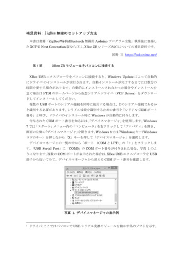
Page 6 of 16To add your XBee(s), click the “Add device” icon –– in theupper-left part of the window. That will prompt this screen to show up:Select your communication port. If you’re lucky (or just don’t have a lot ofstuff connected to your computer) you may only have one option here.Otherwise Windows users should look for the entry that says “USB SerialPort” and Mac users should look for something like “usbserial-XXXXXXXX”.(If you’re using a USB board, that is. If you’re using a Serial Explorer, pickthe “Communications Port” option.)This window also allows you to specify more specific serial characteristicslike baud rate, data bits, and stop bits. Assuming this is the first time you’veused your XBee, you can leave those settings alone. So make sure thosevalues look just as they do in the image above and click Finish.A “Discovering radio modules ” window will briefly scroll by, after whichyou should be presented with the original window, but with an addition tothe “Radio Modules” section on the left. (If X-CTU failed to find a module,check out our troubleshooting page.)Click that new module, and wait a few seconds as X-CTU reads theconfiguration settings of your XBee. You should then be presented with theentire configuration of your XBee.
Page 7 of 16As you can see by scrolling down the right half, there are a lot ofconfiguration settings available. We’ll get to some of those later. For now,though, verify that the configurable settings visible in the screenshot abovematch those of your XBee (channel C, PAN ID 3332, DH 0, DL 0, MY 0).Do It AgainTo test communication between your XBee’s you’ll need to connect yoursecond XBee to a computer as well. That means doing the “Add device”dance one more time.If you have another computer available, you can install X-CTU on that aswell and perform the same set up. You can certainly perform this test withboth XBees connected to the same computer as well, just make sure youselect the correct port number when you’re adding the second XBee.If you add a second XBee to the same computer, a second entry will beadded to the “Radio Modules” list. Selecting either of those entries will showthe configuration settings for that, specific XBee.Note that there are two XBees in the list on the left. The configurationvalues shown are for the highlighted XBee.If you’re ever unsure which XBee is which, try to match up the MACnumbers. These numbers are printed on a sticker on the bottom side ofyour XBee, and they’re also listed in XCTU. (It’s listed as the “SerialNumber” high and low, and is un-modifiable.)
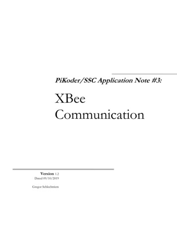
Page 8 of 16Each XBee has a unique MAC address, printed on a sticker in thehighlighted area.As with the last module, make sure all settings are defaulted (channel C,PAN ID 3332, DH 0, DL 0, MY 0). That’ll make the next step possible.Quick and Easy TestClick the “Switch to Consoles” icon –– in the upper-right part ofthe window. This will switch from the configuration tab to the console. Wecan use the console to send characters to an XBee, which will route thatcharacter over-the-air to any other XBee it’s connected to.If you have two XBees connected to your computer, you can switchbetween each radio’s console by selecting the device on the left.First, open a serial connection on each device by clicking the connecticon –. The icon will change, and the border of the console will turngreen.Next, click into the left half of the console, and type a letter or number.You should notice that character echoed in a blue font (the hexadecimaldigits on the right represent the ASCII value). Now click into the otherXBee’s console. As long as it was open, you should see that samecharacter, but red. Try typing a different character into the second XBee’sconsole, and you should see it work the other way.
Page 9 of 16If that worked, then your XBees are configured to talk to each other! If not,check out the troubleshooting page.That your XBees can talk to each other out of the box is no real surprise.They’re all configured to, by default, be on the same network with the sameaddresses. That might be OK, but what if your neighbor is running anXBee-based robot control network, while you’re trying to automate yourhouse? Every time they try to roll a bot forward, your garage door mightopen! To be safe, you should configure your XBees to operate on a uniquenetwork. Fortunately, that, and most other XBee settings are easy tochange. On to the next page!Configuring NetworksAs we’ve mentioned, XBees are awesome because they’re highly – andeasily – configurable. Most of the XBee configuration settings come downto controlling which other XBees it can talk to. On this page, we’ll show youhow to configure three of the most important XBee settings there are: PANID, MY address, and destination address.There are a few levels to XBee networks. First, there’s the channel. Thiscontrols the frequency band that your XBee communicates over. MostXBee’s operate on the 2.4GHz 802.15.4 band, and the channel furthercalibrates the operating frequency within that band. You can usually leavethe channel setting alone, or at least make sure every XBee you want tohave on the same network operates on the same channel.The next level of an XBee network is the personal area network ID (PANID). The network ID is some hexadecimal value between 0 and 0xFFFF.XBees can only communicate with each other if they have the samenetwork ID. There being 65536 possible ID’s, there’s a very small chancethat your neighbor will be operating on the same network (as long as youchange it from the default!).Finally there are MY and destination addresses. Each XBee in a networkshould be assigned a 16-bit address (again between 0 and 0xFFFF), whichis referred to as MY address, or the “source” address. Another setting, thedestination address, determines which source address an XBee can senddata to. For one XBee to be able to send data to another, it must have thesame destination address as the other XBee’s source.For example, if XBee 1 has a MY address of 0x1234, and XBee 2 has anequivalent destination address of 0x1234, then XBee 2 can send data toXBee 1. But if XBee 2 has a MY address of 0x5201, and XBee 1 has a
Page 10 of 16destination address of 0x5200, then XBee 1 cannot send data to XBee 2. Inthis case, only one-way communication is enabled between the two XBee’s(only XBee 2 can send data to XBee 1).We can use X-CTU to easily configure each of those settings. Here’s how:Radio ConfigurationAfter the last page, you should already have at least one XBee connectedto X-CTU. If you’re still over in the console tab, click back over to theConfiguration tab –. Take a peak at the very first handful ofsettings, and you should see some familiar acronyms: CH, ID, DH, DL, andMY. Beside each of those blocks is a text box – that’s where we’ll type inour new settings.Network ID (ID)Begin by coming up with a unique network ID number. Think of yourfavorite number between 0 and 65535, consult your friends and neighborsto make sure your favorite isn’t their favorite, then convert it to hexadecimal.Or if you don’t want to put that much effort into it, use a random value like894B.Type your 16-bit network ID into the white text box next to PAN ID.MY Address (MY)Your next job is to create addresses for each XBee in your network. Thesevalues should be unique to each XBee in a network. The MY address canbe any value between 0x0000 and 0xFFFF. Type this address into the textbox next to “MY 16-bit Source Address”.If you only have two XBees, you can assign the first an MY address of 0,and the other an address of 1.(Your XBee’s can share the same MY address, they’ll both receive thesame data if it’s broadcasted to that address.)Destination Address (DH & DL)The destination address defines which XBee your source XBee is talking to.There are actually two values used to set the destination: destination high(DH) and destination low (DL). You can use that pair of values in one of twoways to set your XBee’s mate:1. Leave DH set to 0, and set DL to the MY address of the receivingXBee.2. Set DH to the Serial Number High (SH) and DL to the SerialNumber Low (SL) of your destination XBee.Either method works, but the former – setting DH to 0 and DL to thedestination’s MY address – is usually easier.
Page 11 of 16Here’s an example for setting up the ID, DH, DL, and MY values for a pairof XBees:SettingAcronymXBee 1XBee 2ChannelCHCCPAN IDID894B 894BDestination Address HighDH00Destination Address Low DL1016-bit Source AddressMY01Notice how the only real differences are the DL and MY values, which areflip-flopped on each XBee.Write ChangesOnce you’ve made your changes to the text field, click the brown pencilicon () to write your changes. The property background should turnfrom green to blue, indicating it has been written to a non-default value.XBee 1’s config tab after writing the changes.Now, just like last time, you can try to send data from one XBee to the othervia the console. As long as the addresses and PAN ID’s match up, youshould have the same success as last time.While it may seem like a lot of work to get right back to where you were,using a unique PAN ID and addressing scheme will make your data transfermore secure and reliable.TroubleshootingIf your XBee’s are giving you any trouble, here are some common problemsand fixes we recommend: Can’t Find Device – If XCTU can’t find your XBee, we recommendrecovery or discovery. XBees Not Communicating Wirelessly – If a pair of XBees are failingto communicate, we recommend resetting everything to default. Resetting XBees – A trick to resetting your XBee (if you don’t have areset button).Can’t Find DeviceAre you having a hard time “finding” an XBee? If you’re “Add Device”process is being followed by a window like this:
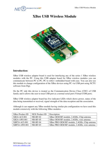
Page 12 of 16There are two options we recommend: discovery or recovery.DiscoveryThe Discover radio devices tool is an extension of “Add devices”. Openthe discovery window by clicking the XBee/magnifying glass icon –– in the top-left.Once again you’ll be prompted to select which communication port yourXBee is connected to. Double check that you’ve selected the correct one(or even try multiple). The next window will present you with every, singleserial setting available, and a whole lot of checkboxes:Most of the cases where your XBee is hiding it’s because the baud ratehas been altered. A quick fix for this is to select all possible baud rates inthe discovery window, then click Finish. The discovery process works a lotlike the add process except it tests out every selection you make in thiswindow – that means it will take a little longer to finish.Hopefully you’ve found an XBee that was just configured to talk at a weirdbaud rate. If not you can select any of the other checkboxes as well, but it’llmake for a longer and longer discovery process. Click every checkbox andyou might be waiting upwards of an hour for your XBee to be discovered(permutations!).If you’re not having any luck with discovery, the next step is recovery.
Page 13 of 16RecoveryIf your XBee seems bricked, don’t worry! You can most likely recover it. Toget to the recovery screen, click the Tools icon, and select XBeeRecovery.Once again, you’ll need to select your COM port, and you’ll also need toselect the product family. This can be found on the bottom sticker of yourXBee. If you’re using a series 1 module, the family should be XB24.Beyond that you’ll need to select a “Function Set” and “Firmware Version”.For both of those you should be safe selecting the top-most values in thelist.Once you’ve made all of those selections, click Recover.The recovery process may take a few minutes. You’ll be prompted to resetyour XBee. If your Explorer has a reset button, simply press it whenprompted, otherwise see the “Reset” section below.During recovery, if XCTU can find your XBee it will. It’ll also update thefirmware, and set you back to the default settings. If you know what gotyour XBee bricked in the first place maybe don’t do that again.XBee’s Not Communicating, Reset to DefaultsIf no matter what changes you make to the config settings your XBee’s justwon’t communicate with each other, try resetting them both to the defaultvalues.In the config tab, click the “Load default firmware settings” icon –(not sure how to describe that icon). Then click Yes to confirm that youwant to reset everything.If you’re presented with any red-backgrounded error notifications (likebelow), first try to refresh the value, by clicking the green icon –.
Page 14 of 16If that doesn’t fix the error, you can probably get away with typing a “0” inthat box (usually this pops up for properties like encryption keys or othervalues meant to be kept secret).After you’ve loaded the default values, you still need to write the settingsby clicking the big pencil icon above –.After defaulting both radios, the addresses, networks, and other settingsshould all be compatible. Try communicating over the console again.Resetting Old (Pre-Reset Button) ExplorersWhen it’s having trouble communicating with an XBee, XCTU may presentyou with a notification like this:The USB explorers were revised in May 2014 to include a reset button, soresetting should be easily done on those newer boards. However, if you’reusing an older Explorer you’ll have to use the “jumper method”. Grab apiece of jumper wire and, when prompted with the “Action Required”window, briefly connect the RST pin to GND.
Page 15 of 16Short them together for about a second, and then remove the wire. If you’vedone it within the time window provided by XCTU, it should proceed to thenext step. If not give it another try it takes some practice.Resources & Going FurtherThat should be enough to get you started. If you’re looking for more XBeeand XBee Shield info, check out these resources: XBee Explorer Schematic – If you’re confused about how parts areinterconnected on the breakout, check out this PDF. XBee Explorer GitHub Repo – This is where you’ll find the latest andgreatest PCB design files. XBee Series 1 Manual – For more advanced users, if you really wantto take advantage of the XBee’s unique abilities, check out thisguide. XBee Wireless Class Materials – Check out our teaching materialsfor the XBee class we lead every once-in-a-while.Going FurtherWith XBee and the XBee Explorer you have most of the tools you’ll need totake your project to the airwaves. If you’re looking to add Arduino to themix, we recommend using an XBee Shield and following along with ourXBee Shield Hookup Guide.What are you going to make? Need some inspiration? Check out theserelated tutorials: XBee WiFi Hookup Guide – Take the next step with XBees, using theXBee WiFi. These modules allow you to connect to a wirelessnetwork and give your Arduino Internet access! Simon Splosion Wireless – This tutorial demonstrates one of manytechniques to “hack” the Simon Says – use XBee’s to make theSimon game wireless!
Page 16 of 16 Getting Started With the RedBot – The RedBot is our popular,Arduino-based robot platform. Once you get it rolling, you can take ita step further by controlling it with an g-xbees-and-xctu? ga 1.266449614.19394569. 6/24/2015
The Explorers: USB Explorer, Explorer Dongle, and Serial Explorer. With an XBee Explorer connected between your computer and your XBee, and with the help of the X-CTU software, you can easily configure XBees, test connections, and pass data between your computer and remote