Transcription
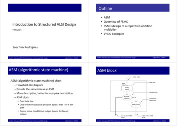
OutlineIntroduction to Structured VLSI Design‐ FSMD’s ASM Overview of FSMD FSMD design of a repetitive‐additionmultiplier VHDL ExamplesJoachim RodriguesJoachim Rodrigues, EIT, LTH, Introduction to Structured VLSI Designjrs@eit.lth.se FSMD’sASM (algorithmic state machine)Joachim Rodrigues, EIT, LTH, Introduction to Structured VLSI Designjrs@eit.lth.se FSMD’sASM blockASM (algorithmic state machine) chart– Flowchart‐like diagram– Provide the same info as an FSM– More descriptive, better for complex description– ASM block One state box One ore more optional decision boxes: with T or F exitpath One or more conditional output boxes: for MealyoutputJoachim Rodrigues, EIT, LTH, Introduction to Structured VLSI Designjrs@eit.lth.se FSMD’sJoachim Rodrigues, EIT, LTH, Introduction to Structured VLSI Designjrs@eit.lth.se FSMD’s
State Diagram and ASM Chart conversionMooreJoachim Rodrigues, EIT, LTH, Introduction to Structured VLSI DesignState Diagram and ASM Chart conversionMealy and Moorejrs@eit.lth.se FSMD’sState Diagram and ASM Chart conversionJoachim Rodrigues, EIT, LTH, Introduction to Structured VLSI Designjrs@eit.lth.se FSMD’sIntroduction How to realize an algorithm in hardware? Two characteristics of an algorithm:– Use of variables (symbolic memory location)e.g., n n 1 in C– Sequential execution(execution order is important)Corresponding book chapter (10) is availableas pdf on the course homepageJoachim Rodrigues, EIT, LTH, Introduction to Structured VLSI Designjrs@eit.lth.se FSMD’sJoachim Rodrigues, EIT, LTH, Introduction to Structured VLSI Designjrs@eit.lth.se FSMD’s
AlgorithmHDL Implementation “Dataflow” implementation in VHDL– Summate 4 numbers– Divide the result by 8– Round the result– Convert the algorithm in to combinational circuit– No memory elements– The sequence is embedded into the “flow of data” PseudocodeJoachim Rodrigues, EIT, LTH, Introduction to Structured VLSI DesignThe instructions are”sequential”, BUT.jrs@eit.lth.se FSMD’sHW‐mappingJoachim Rodrigues, EIT, LTH, Introduction to Structured VLSI Designjrs@eit.lth.se FSMD’sDataflow implementation‐ drawbacks instructions will be executed concurrently Problems with dataflow implementation:– Can only be applied to trivial algorithm– Not flexible Can we just share one adder in a time‐multiplexing fashion to save hardwareresources What happen if input size is not fixed(i.e., size is determined by an external input)Joachim Rodrigues, EIT, LTH, Introduction to Structured VLSI Designjrs@eit.lth.se FSMD’sJoachim Rodrigues, EIT, LTH, Introduction to Structured VLSI Designjrs@eit.lth.se FSMD’s
Basic RT operationRegister Transfer Methodology Realized algorithm in hardware Use register to store intermediate data and imitatevariable Use a data path to realize all register operations Use a control path (FSM) to specify the order of registeroperation The system is specified as sequence of datamanipulation/transfer among registers Realized by FSM with a data path (FSMD)Joachim Rodrigues, EIT, LTH, Introduction to Structured VLSI Designjrs@eit.lth.se FSMD’sImplementation example Basic form: Interpretation:– At the rising edge of the clock, theoutput of registers rsrc1 rsrc2 etc. areavailable.– The output are passed to acombinational circuit that performsf( ).– At the next rising edge of the clock,the result is stored into rdestJoachim Rodrigues, EIT, LTH, Introduction to Structured VLSI Designjrs@eit.lth.se FSMD’sImplementation example Multiple RT operationsJoachim Rodrigues, EIT, LTH, Introduction to Structured VLSI Designjrs@eit.lth.se FSMD’sJoachim Rodrigues, EIT, LTH, Introduction to Structured VLSI Designjrs@eit.lth.se FSMD’s
FSM timingFSM as control path FSM is a good to control RT operation– State transition is on clock‐by‐clock basis– FSM can enforce order of execution– FSM allows branches on execution sequence Normally represented in an extendedASM chart known as ASMD (ASM withdatapath) chartNote: new value of r1 is only available when theFSM enters s2 stateJoachim Rodrigues, EIT, LTH, Introduction to Structured VLSI Designjrs@eit.lth.se FSMD’sJoachim Rodrigues, EIT, LTH, Introduction to Structured VLSI Designjrs@eit.lth.se FSMD’sFSMD design exampleBasic Block Diagram of FSMDRepetitive addition multiplier Basic algorithm: 7*5 7 7 7 7 7Pseudo codeJoachim Rodrigues, EIT, LTH, Introduction to Structured VLSI Designjrs@eit.lth.se FSMD’sJoachim Rodrigues, EIT, LTH, Introduction to Structured VLSI DesignASMD‐friendly codejrs@eit.lth.se FSMD’s
ASMD ChartRecipe Construction of the data path Input:––––– a in, b in: 8‐bit unsigned– clk, reset– start: command Output:– r: 16‐bit unsigned– ready: statusList all RT operationsGroup RT operation according to the destination registerAdd combinational circuit/muxAdd status circuits ASMD chart– Default RT operation: keep theprevious value– Note the parallel execution inop stateJoachim Rodrigues, EIT, LTH, Introduction to Structured VLSI Designjrs@eit.lth.se FSMD’sJoachim Rodrigues, EIT, LTH, Introduction to Structured VLSI Designjrs@eit.lth.se FSMD’sRegister in datapth Continue withCircuit associated with r register– n‐register– a‐registerab0Joachim Rodrigues, EIT, LTH, Introduction to Structured VLSI Designjrs@eit.lth.se FSMD’sJoachim Rodrigues, EIT, LTH, Introduction to Structured VLSI Designjrs@eit.lth.se FSMD’s
EntitySequential Process (state registers) VHDL code: follow the block diagramJoachim Rodrigues, EIT, LTH, Introduction to Structured VLSI Designjrs@eit.lth.se FSMD’sFSM ImplementationJoachim Rodrigues, EIT, LTH, Introduction to Structured VLSI DesignJoachim Rodrigues, EIT, LTH, Introduction to Structured VLSI Designjrs@eit.lth.se FSMD’sSequential Process (data registers)jrs@eit.lth.se FSMD’sJoachim Rodrigues, EIT, LTH, Introduction to Structured VLSI Designjrs@eit.lth.se FSMD’s
Multiplexer RoutingFunctional UnitsJoachim Rodrigues, EIT, LTH, Introduction to Structured VLSI Designjrs@eit.lth.se FSMD’sJoachim Rodrigues, EIT, LTH, Introduction to Structured VLSI Designjrs@eit.lth.se FSMD’sjrs@eit.lth.se FSMD’sJoachim Rodrigues, EIT, LTH, Introduction to Structured VLSI Designjrs@eit.lth.se FSMD’sRegister in decision box– Register is updated when the FSM exits current state– How to represent count 0 ‘1’ using register?n will be updated withthe next clockOne extra clockrequiredJoachim Rodrigues, EIT, LTH, Introduction to Structured VLSI Design
FSM as control path FSM is a good to control RT operation - State transition is on clock‐by‐clock basis - FSM can enforce order of execution - FSM allows branches on execution sequence Normally represented in an extended ASM chart known as ASMD (ASM with datapath) chart