Transcription
INTERCONNECTIONNETWORKSLE CTU RE 4D R . S A M M AN H . A ME EN1
Topology Specifies way switches are wired Affects routing, reliability, throughput, latency, building ease Routing How does a message get from source to destination? Static or adaptive Buffering and Flow Control What do we store within the network? (Entire packets, parts ofpackets, etc?) How do we manage and negotiate buffer space? Tightly coupled with routing strategyPAGE 2
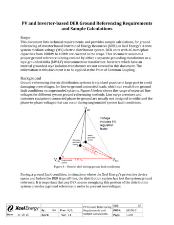
Network interface Connects endpoints (e.g. cores) to network. Decouples computation/communication Links Bundle of wires that carries a signal Switch/router Connects fixed number of input channels to fixednumber of output channels Channel A single logical connection between routers/switchesPAGE 3
These are fundamental decisions in determining theappropriate architecture of an interconnectionnetwork (IN) for parallel machines. The decisionsare made between :- Mode of Operation Control strategy Switching methodology Network topologyPAGE 4
INs are classified as synchronous versus asynchronous. In synchronous mode of operation, a single global clock is used by allcomponents in the system such that the whole system is operating in alock–step manner. Asynchronous mode of operation, on the other hand, does not requirea global clock. Handshaking signals are used instead in order tocoordinate the operation of asynchronous systems. While synchronoussystems tend to be slower compared to asynchronous systems, theyare race and hazard-free.PAGE 5
A typical interconnection network consists of a number of switching elementsand interconnecting links. Interconnection functions are realized by properly setting control of theswitching elements. The control-setting function can be managed by a centralized controller or bythe individual switching element. The latter strategy is called distributed controland the first strategy corresponds to centralized control. Most existing SIMDinterconnection networks choose the centralized control on all switch elementsby the control unit.PAGE 6
The two major switching methodologies are circuit switching and packet switching.circuit switching sets up a full path (acquires all resources) between sender and receiverprior to sending a message Reserve link than send data Higher bandwidth transmission (no link management overhead) Overhead to set up a path Reserving link can results in low utilizationIn packet switching, data is put in a packet and routed through the interconnectionnetwork without establishing a physical connection path. In general, circuit switching ismuch more suitable for bulk data transmission, and packet switching is more efficient formany short data messages. Route packets individually (possibly on different network links) Opportunity to use link whenever a link is idle Overhead due to dynamic switchingMost SIMD interconnection networks are hardwired to assume circuit switching operations. Packetswitched networks have been suggested mainly for MIMD machines.PAGE 7
A network can be depicted by a graph in which nodes represent switching points andedges represent communication links. The topologies tend to be regular and can be grouped into two categories: static anddynamic. In a static topology, links between two processors are passive and dedicated busescannot be reconfigured for direct connections to other processors. On the other hand,links in the dynamic category can be reconfigured by setting the network's activeswitching elements. The choice of a particular interconnection network depends on the application demands,technology supports, and cost- effectiveness.PAGE 8
Regular or Irregular regular if topology is regular graph (e.g. ring, mesh) Routing Distance number of links/hops along route Diameter maximum routing distance Average Distance average number of hops across all valid routesPAGE 9
PAGE 10
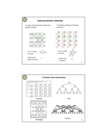
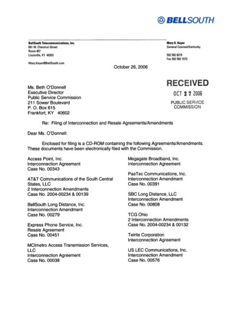
STATIC NETWORKSThe inter-PE communication network can bespecified by a set of data- Routing Static networksTopologies in the static networks can be classifiedaccording to the dimensions required for layout. Forillustration, one-dimensional, two-dimensional,three-dimensional, and hypercube are shown innext slidePAGE 11
PAGE 12
We consider two classes of dynamic networks:single-stage versus multistage, as describedbelow separately. Single-stage networks A single-stage network isa switching network with N input selectors (IS)and N output selectors The single-stage network is also called arecirculating network. Data items may have torecirculate through the single stage several timesbefore reaching their final destinations.PAGE 13
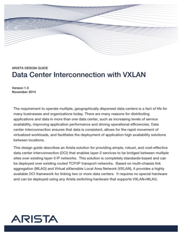
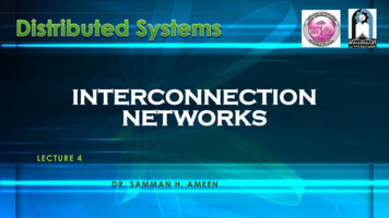
Many stages of interconnected switches form a multistage SIMD network. Multistagenetworks are described by three characterizing features: the switch box, thenetwork topology, and the control structure. Many switch boxes are used in amultistage network. Each box is essentially an interchange device with two inputsand two outputs Illustrated are four states of a switch box: straight, exchange, upperbroadcast, and lower broadcast. A two-function switch box can assume either thestraight or the exchange states. A four-function switch box can be in any one of thefour legitimate states.PAGE 14
A network is called a re-arrangeable network if itcan perform all possible connections betweeninputs and outputs by rearranging its existingconnections so that a connection path for a newinput-output pair can always be established.PAGE 15
Static networks are opposite of dynamic networks interms of network status, meaning that static networksare fixed and can be unidirectional or bi-directionalbetween processors. There exist two types of staticnetworks Completely connected Networks(CCN) Limited Connection Networks (LCN) Linear ArraysRings (Loops)Two-Dimensional Arrays and ToriTree NetworksN-Cube NetworksPAGE 16
(Node Degree) d the number of edges incident on a node. (Diameter) D the maximum shortest path between any twonodes. Bisection width is the minimum number of links that must becut to divide the network into two equal halves(Lowbisection width means low data transfer and high bisectionmeans high level of data transfer may happen). Network latency: worst-case time for a unit message to betransferred Hardware complexity: implementation costs for wire, logic,switches, connectors, etc.PAGE 17
A CCN consists of any number of nodes, where all nodes areconnected to each other. The network diameter is therefore andD 1 the node degree is d N-1 (a node is connected to all othernodes, except itself). the Bisection Width of a CCN is b N2/4 .Needs N(N-1)/2 links toconnect N processor nodes.Example N 16 - 136 connections. N 1,024 - 524,288 connections D 1 d N-1 b N2/4PAGE 18
Linear Arrays and Ringsa linear array’s nodes are connected to eachother, forming a straight line. This is anasymmetric network: all nodes have adegree of 2, with the exception of the endnodes, which have a degree of 1The network has a bisection width of 1.Asymmetric networkDegreed 2DiameterD N-1Bisection bandwidth:b 1Allows for using different sections of the channel by differentsources concurrently.one serious disadvantage is that this network’s diameter increases proportionally with the numberof nodes. As a result, this topology is not scalable.PAGE 19
The ring topology attempts tosolve the “large diameter”problem inherent in linear arrays.As shown below, the ring is simplya linear array, with its end nodesconnected together. This has theeffect of making the networksymmetric: all nodes have adegree of 2.Linear ArrayRingRing arranged to use short wiresD N / 2 d 2D N-1 for unidirectional ring orD N/2for bidirectional ringPAGE 20
the processors are located at the leaves all other nodesare switches.A k-ary tree has heightDiameter D 2(h)bisection width of the tree is b 1the bisection width of the tree is 1 resulting in poor bandwidthat the root level. One solution for this problem is the fat tree(discussed below).PAGE 21
The fat tree solves the bandwidth problem by doubling the number of connections at each level in the tree; eachprocessor, however, still has a degree of 1, as shown in the figure below.PAGE 22
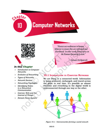
In an n-dimensional cube (n-cube) network, there are N 2n processors, and each processor isconnected to n other processors. Each PE is connected to (d log N) other PEs100 d log2 N, 000110010101b N/2 2n-1001 Binary labels of neighbor PEs differ in only one bit0-D1-D2-D1110113-D A d-dimensional hypercube can be partitioned into two(d-1)-dimensional hypercubes The distance between Pi and Pj in a hypercube: thenumber of bit positions in which i and j differ (ie. theHamming distance)100000 10011 01001 11010010101 Example:001110111011 Distance between PE11 and PE9 is 3 D log2 N4-DPAGE 23
mesh is an asymmetric network, where the corner nodes have d 2, the sides d 3, and thecentre nodes d 4. k-dimensional mesh has N nk nodes. d 2k except at boundary nodes.meshLike the ring topology, the torus topology attempts todecrease the network diameter, for a given number ofnodes. The usual diameter of a 2-dimensional mesh isThe torus, on the other hand, has a diameter ofeffectively reducing the diameter by a factor of k.However, this has the effect of increasing thebisection width by the same amount fromtoFurthermore, the torus network is symmetric since allnodes now have a degree d 4.,torusPAGE 24
Single Bus Systems A single bus is considered the simplest way to connect multiprocessor systems. Such a system consists of N processors, each having its own cache, connected by ashared bus Although simple and easy to expand, single bus multiprocessors areinherently limited by the bandwidth of the bus and the fact that only one processorcan access the bus, and in turn only one memory access can take place at anygiven time.PAGE 25
Advantages Simple Cost effective Easy to implementDisadvantages High contention: all nodes contend for shared bus Limited bandwidth: all nodes communicate oversame wiresPAGE 26
The use of multiple buses to connect multiple processors is anatural extension to the single shared bus system. A multiple bus multiprocessor system uses several parallelbuses to interconnect multiple processors and multiple memorymodules. A number of connection schemes are possible in this case.Among the possibilities are : multiple bus with full bus–memory connection (MBFBMC), multiple bus with single bus memory connection (MBSBMC), multiple bus with partial bus-memory connection (MBPBMC), multiple bus with class-based memory connection (MBCBMC).PAGE 27
MULTIPLE BUS WITH FULL BUS–MEMORYCONNECTION (MBFBMC),PAGE 28
MULTIPLE BUS WITH SINGLE BUS MEMORYCONNECTION (MBSBMC)PAGE 29
MULTIPLE BUS WITH PARTIAL BUS-MEMORYCONNECTION (MBPBMC)PAGE 30
MULTIPLE BUS WITH CLASS-BASED MEMORYCONNECTION (MBCBMC)PAGE 31
PAGE 6 A typical interconnection network consists of a number of switching elements and interconnecting links. Interconnection functions are realized by properly setting control of the switching elements. The control-setting function can be managed by a centralized controller or by the individual switching element. The latter strategy is called distributed control