Transcription
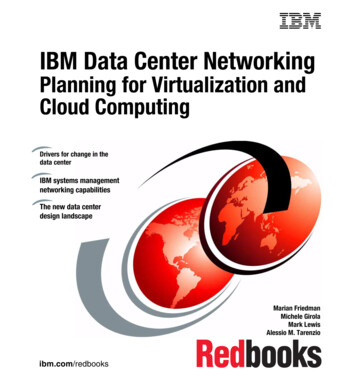
ARISTA DESIGN GUIDEData Center Interconnection with VXLANVersion 1.0November 2014The requirement to operate multiple, geographically dispersed data centers is a fact of life formany businesses and organizations today. There are many reasons for distributingapplications and data in more than one data center, such as increasing levels of serviceavailability, improving application performance and driving operational efficiencies. Datacenter interconnection ensures that data is consistent, allows for the rapid movement ofvirtualized workloads, and facilitates the deployment of application high availability solutionsbetween locations.This design guide describes an Arista solution for providing simple, robust, and cost-effectivedata center interconnection (DCI) that enables layer-2 services to be bridged between multiplesites over existing layer-3 IP networks. This solution is completely standards-based and canbe deployed over existing routed TCP/IP transport networks. Based on multi-chassis linkaggregation (MLAG) and Virtual eXtensible Local Area Network (VXLAN), it provides a highlyavailable DCI framework for linking two or more data centers. It requires no special hardwareand can be deployed using any Arista switching hardware that supports VXLAN MLAG.
TABLE OF CONTENTS!THE DRIVERS FOR DATA CENTER INTERCONNECTION . 3!DATA CENTER INTERCONNECTION TECHNOLOGIES . 4!PSEUDOWIRE & TUNELLING SOLUTIONS . 4 !VXLAN: A SCALABLE, STANDARDS-BASED DCI SOLUTION . 5 !INTRODUCING THE ARISTA NETWORKS DCI WITH VXLAN SOLUTION . 6!MAC LEARNING AND THE FORWARDING OF BROADCAST & MULTICAST TRAFFIC . 7 !ARISTA DCI SOLUTION COMPONENTS . 7!ARISTA NETWORKS VXLAN HARDWARE VTEP GATEWAY . 7 !LICENSING & PLATFORM SUPPORT . 8 !ARISTA MULTI-CHASSIS LINK AGGREGATION (MLAG) . 9 !ARISTA VXLAN MLAG SOLUTION . 11 !DEPLOYING THE ARISTA VXLAN DCI SOLUTION . 12!INTEGRATING ARISTA DCI SOLUTION WITH EXISTING NETWORKS . 12 !CONFIGURATION EXAMPLE . 14!THE PHYSICAL TOPOLOGY . 14 !THE MLAG TOPOLOGY . 16 !VXLAN AND LAYER-3 TOPOLOGIES . 21 !VERIFYING & MONITORING THE ARISTA VXLAN DCI SOLUTION . 26!OPERATION OF THE VXLAN DCI SOLUTION WITH FAILURE CONDITIONS . 28!NORMAL OPERATION . 28 !AN MLAG MEMBER LINK FAILURE . 29 !AN INTER-SITE LINK FAILURE . 31 !CONCLUSION . 33!ARISTA DESIGN GUIDEDATA CENTER INTERCONNECTION WITH VXLAN2
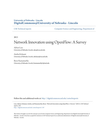
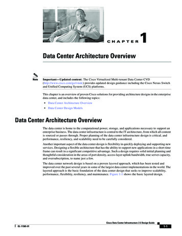
THE DRIVERS FOR DATA CENTER INTERCONNECTIONOperating multiple, geographically dispersed data centers has been regarded as best practice for many years,and all types of businesses and organizations use this deployment model. Today, it may even be a statutoryrequirement for some businesses (e.g., banking and finance), or a part of an organization’s governance policy.The original reason for building and operating multiple data centers was to ensure business continuity. Therationale was simple: it was highly unlikely that an issue affecting power or service provision in one part of theworld would also impact another location (provided they are adequately far apart). A beneficial side-effect ofdispersing applications and data was that they could be positioned close to the ultimate consumers of the service,which in turn meant users experienced better response times, resulting in improved productivity (or in the case ofcustomers, greater satisfaction with the service). The consequence of locating services close to users was thatthere was less demand for bandwidth on expensive wide-area connections, thus reducing operational costs.With the dispersion of applications and data came the need to ensure consistency of information betweenlocations. This has driven the need to interconnect data center locations for the purposes of data replication andto enable shared information processing between servers forming geographically dispersed clusters.More recently, additional drivers for data center interconnection (DCI) have emerged. The widespread use ofserver virtualization has delivered the potential to provide live migration of compute workloads (e.g., applications,virtual desktops, etc.) between sites. The original reason to provide the live migration of workloads was forimproved service availability. However, this ability to move workloads between locations has given rise to otheruse cases; for example, applications can be moved to locations to be close to service users (e.g., “follow-thesun”) or to where power is cheaper (e.g., “follow-the-moon”).Figure 1: Some of the Typical Use Cases for Data Center InterconnectionARISTA DESIGN GUIDEDATA CENTER INTERCONNECTION WITH VXLAN3
With the advent of cloud computing models for IT service delivery, the dynamic provisioning of workloads, and thecapability to instantiate applications on demand (often without consideration of location), the possibility that theconstituent elements of an application could be split across different data centers becomes a reality. Likewise,cloud solutions may choose to “re-balance” a workload based on specific operational criteria. For example, virtualmachines (VM) may be automatically moved from a server requiring downtime for maintenance, or workloads maybe redistributed across physical hosts in order to optimize power distribution or cooling. It is quite possible thatVMs could be placed on physical servers in different data centers.Data center interconnection is often required as a temporary measure to facilitate the permanent migration ofapplications and data from one location to another. For example, many organizations are seeking to consolidateand rationalize their data centers in order to improve efficiency and reduce operating costs. In this case, atemporary DCI solution can be deployed to transfer data and applications from a site due for closure to their newhome. Migration can also be a requirement when businesses merge or are acquired, where the need to rationalizeresources and locations is deemed necessary. The reverse scenario is also true, as in the case of a businessdivesting part of its operation, where IT services need to relocate to the new organization's facilities.Ultimately there are many circumstances driving need for data center interconnection and, in reality, businessesmay have a combination of the requirements described above. It is likely that new requirements will emerge in thefuture, especially as adoption of the cloud computing paradigm continues. In the next section we will considersome of the technical requirements for delivering a DCI solution.DATA CENTER INTERCONNECTION TECHNOLOGIESMost network designers would prefer that data center interconnection over wide area networks (WAN) beperformed at layer 3, without layer-2 connectivity spanning data centers. However, application requirementsoften make it necessary to provide layer-2 interconnection between data centers, with common IP subnets andVLANs stretched across sites. While it is true that some VM mobility solutions have removed the need to providelayer-2 connectivity between locations, many current solutions still require layer-2 interconnection. This is alsotrue of many high availability clustering systems and storage virtualization and replication solutions, whichmandate layer-2 adjacency between physical nodes.However, native, long-distance, layer-2 connections such as local area network (LAN) extension services can beextremely difficult to find, especially outside of metropolitan areas or at distances that ensure data centers areadequately geographically dispersed to provide full protection from outages. Even where native layer-2 servicesare available, it may be undesirable to use them due potential “fate-sharing” between sites, as in the case of alayer-2 problem such as a broadcast storm on one site impacting the other data center.PSEUDOWIRE & TUNELLING SOLUTIONSThe challenges associated with providing cost-effective, long-distance layer-2 interconnection led to thedevelopment of a set of solutions based on tunneling mechanisms. These were designed to allow layer-2 traffic tobe transported over Layer-3 networks. Originally these solutions centered on the concept of a “pseudowire,”which allowed for the emulation of point-to-point Ethernet links by tunneling all traffic over wide area networks.Tunneling mechanisms such as Generic Router Encapsulation (GRE), Layer-2 Tunneling Protocol (L2TP), or MultiProtocol Label Switching (MPLS), provided the underlying framework for this approach. Unfortunately, the initialsolutions that emerged in this space, such as EoGRE (Ethernet over GRE), EoMPLS (Ethernet over MPLS), AToM(Any Transport over MPLS) did not scale well. For example, to allow any-to-any communication across multiplesites, full mesh connectivity of point-to-point tunnels links was required. As a result, they proved difficult toARISTA DESIGN GUIDEDATA CENTER INTERCONNECTION WITH VXLAN4
deploy and very complex to troubleshoot. Also, due the unfiltered transmission of all traffic, these solutions didnot deliver the necessary level of fault isolation between locations.In order to overcome some of the limitations of the point-to-point tunneling approach described above,technologies such as Virtual Private LAN Service (VPLS) were developed to allow the multipoint emulation of LANservices over underlying pseudowires. While this solution addressed some of the challenges associated withearlier approaches, in that it allowed multipoint connectivity and offered improved fault isolation between sites, itadded the complexity associated with the underlying MPLS infrastructure necessary to support it.In recent years, much of the industry effort to find a simple, robust, multipoint mechanism for carrying layer-2traffic over layer-3 networks has polarized into distinct camps, with very little cross-vendor support. Thesesolutions, which include OTV (Overlay Transport Virtualization) from Cisco, and Juniper’s EVPN (Ethernet VirtualPrivate Network), have aimed to address customer requirements for DCI solutions, but have lacked anywidespread support from other vendors, essentially locking customers into a single supplier for their inter-datacenter connectivity. Even within the individual vendors, support for their respective solutions can be very limited,often restricted to high-end and costly devices; for example, Cisco’s OTV is only available on the Nexus 7000platform with M-series modules and the ASR 1000 router.VXLAN: A SCALABLE, STANDARDS-BASED DCI SOLUTIONGiven a blank sheet of paper it would not be difficult to define the desirable characteristics of layer-2-capabledata center interconnect solutions. Ideally, any modern DCI solutions should meet the following basic criteria: Transparent to applications Transport agnostic – can operate over any IP-based service Multiple path and multiple site support Capable of providing fault isolation between data centers Interoperable and standards based Simple to implement Platform independent – no need for specialized hardware or equipment Managed and controlled as part of the wider DC infrastructure – not an “alien” technologyThe foundation of the Arista solution is Virtual eXtensible Local Area Network (VXLAN), an open IETFspecification designed to standardize an overlay encapsulation protocol, capable of relaying layer-2 traffic over IPnetworks. VXLAN has wide industry support and was authored by Arista, Cisco and VMware with support fromBroadcom, Citrix and Red Hat among others.Arista’s solution for data center interconnect meets these requirements and represents the industry’s first trulyopen standards-based, simple to deploy and manage DCI system. It is cost-effective, running on standardswitching hardware, and it provides active-active switch redundancy and can interoperate with wide range ofother data center switches, including those from other vendors.ARISTA DESIGN GUIDEDATA CENTER INTERCONNECTION WITH VXLAN5
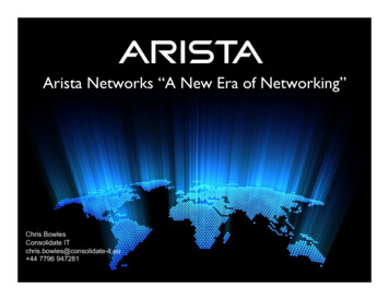
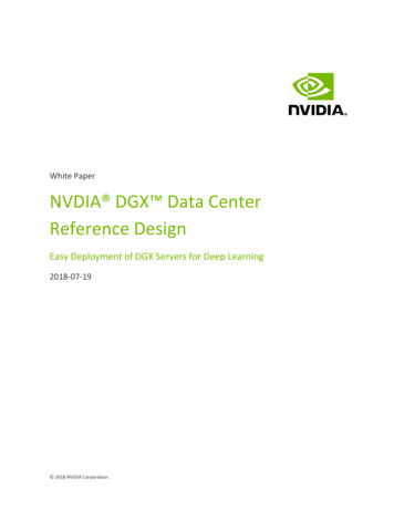
INTRODUCING THE ARISTA NETWORKS DCI WITH VXLAN SOLUTIONVXLAN was designed for the creation of logical layer-2 domains on top of an underlying IP network, initially toenable network virtualization in the data center. VXLAN identifies individual layer-2 domains using a 24-bit virtualnetwork identifier (VNI), allowing for up to 16 million independent domains to be specified. layer-2 Ethernetframes are encapsulated in IP UDP datagrams and are relayed transparently over the IP network. It is the inherentability to relay unmodified layer-2 traffic transparently over any IP network that makes VXLAN an ideal technologyfor data center interconnection.Within the VXLAN architecture, virtual tunnel end points (VTEP) perform the encapsulation and de-encapsulationof layer-2 traffic. Each VTEP is identified by an IP address, which is assigned to a virtual tunnel interface (VTI).The VTEP receives standard layer-2 Ethernet frames, selects the correct VNI and forms an IP UDP packet fortransmission to one or more destination VTEPs. The source IP address is that of the sending VTI; the destinationIP address is that of the receiving VTI.The VNI is typically determined based on the IEEE 802.1Q VLAN tag of the frame received. The destination VTEP(or VTEPs in the case of multicast or broadcast traffic) is selected using a destination-to-VTEP map. This map isvery similar to the MAC bridging table, except MAC addresses are associated with IP addresses rather thanswitch interfaces.Figure 2: VXLAN Components and OperationARISTA DESIGN GUIDEDATA CENTER INTERCONNECTION WITH VXLAN6
MAC LEARNING AND THE FORWARDING OF BROADCAST & MULTICAST TRAFFICIn order to transparently support layer-2 traffic, each VTEP must handle the forwarding of broadcast and multicasttraffic as well as ensure previously “unseen” MAC addresses and their “locations” are learned. In a layer-2network, MAC address learning is performed by flooding frames with unknown unicast addresses on all portswithin a given VLAN. For VXLAN, the approach specified in the IETF RFC is based on IP multicast. In thisscenario, one or more IP multicast groups are set up to carry unknown unicast broadcast and multicast traffic toVTEPs associated with a given VNI.This approach means that the underlying IP network used to transport VXLAN encapsulated traffic must supportIP multicast. However, many wide area networks used to interconnect data centers do not support or implementIP multicast. To alleviate this issue, Arista has introduced a feature referred to as “Head End Replication” (HER),which takes incoming broadcast, multicast, and unknown unicast traffic and sends a single unicast copy to eachof the VTEPs receiving traffic for a given VNI.ARISTA DCI SOLUTION COMPONENTSThe foundation of the Arista solution for data center interconnection is the VXLAN Hardware Gateway, deployed inconjunction with multi-chassis link aggregation (MLAG).In addition, Arista’s Virtual ARP (vARP) mechanism can be used to ensure redundant first-hop router interfaces arelocalized within the data center, in order to prevent traffic destined to exit the data center from consumingbandwidth on the links interconnecting data centers.ARISTA NETWORKS VXLAN HARDWARE VTEP GATEWAYFigure 3: Arista Hardware VXLAN Gateway ArchitectureARISTA DESIGN GUIDEDATA CENTER INTERCONNECTION WITH VXLAN7
Configuring the Arista VXLAN Hardware Gateway is extremely simple. An IP address for each VTEP is specifiedusing a loopback interface, which is in turn mapped to the VTI (referred to as the “vxlan 1” interface). The defaultIP port for VXLAN traffic is UDP 4789, although this can be changed if requiredEach VTEP performs local-VLAN-to-VXLAN-VNI mapping, enabling VLAN translation to be performed as part ofthe tunneling process if required (i.e., source and destination VLAN IDs can be different). The Arista VXLANHardware Gateway is capable of emulating layer-2 local area networks (LANs), so both point-to-point and pointto-multi-point logical layer-2 topologies are supported with the ability to deliver broadcast, multicast and unknownunicast traffic. Each VTEP filters spanning tree BPDUs ensuring that each DC is an independent spanning treedomain, helping isolate potential faults.The initial version of Arista’s VXLAN gateway handled the flooding of broadcast, multicast and unknown unicasttraffic using a single, configurable multicast group. Later versions of Arista EOS introduced the option to useHead End Replication (HER), which allows traffic with multiple destinations (i.e., broadcast or multicast frames) ortraffic requiring flooding (i.e., unknown unicast frames) to be relayed in individual IP unicast packets, thuseliminating the need to implement multicast on the layer-3 transport network.Figure 4: Arista VXLAN Point-to-Point & Multipoint VNIs with VLAN TranslationLICENSING & PLATFORM SUPPORTVXLAN requires the Arista V- Virtualization Features License. Full details of VXLAN feature availability and platformsupport can be found at: sARISTA DESIGN GUIDEDATA CENTER INTERCONNECTION WITH VXLAN8
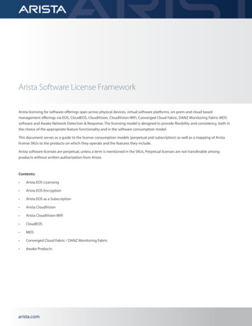
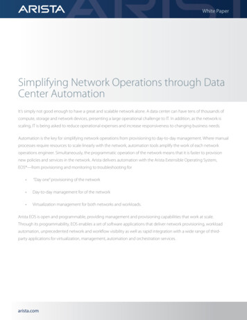
ARISTA MULTI-CHASSIS LINK AGGREGATION (MLAG)Arista’s multi-chassis link aggregation (MLAG) enables ports on two separate switches to be combined into asingle Ethernet port channel. For example, two 10-gigabit Ethernet ports, one each from two MLAG-configuredswitches, can connect to two 10-gigabit ports on a host, switch, or network device to create a link that appears asa single 20-gigabit port channel. MLAG-configured ports effectively provide layer-2 multi-path forwarding, thusincreasing bandwidth, providing higher availability and improving efficiency by avoiding the need to have eitheractive-standby connections or to rely on spanning tree to block alternate paths.With MLAG, two aggregation switches create a single logical layer-2 switching instance that utilizes allconnections to the switches. Interfaces on both devices participate in a distributed port channel, enabling allactive paths to carry data traffic while maintaining the integrity of the Spanning Tree topology.Arista MLAG provides these benefits: Provides higher bandwidth links as network traffic increases. Utilizes bandwidth more efficiently with fewer uplinks blocked by STP. Connects to other switches and servers by static LAG or IEEE 802.3AX Link Aggregation Control Protocol(LACP) without the need for proprietary protocols. Aggregates up to 32 10-Gbps Ethernet ports across two switches: 16 ports from each switch. Supports normal Spanning Tree Protocol (STP) operation to prevent loops. Supports active-active layer-2 redundancy.An MLAG consists of two or more links that terminate on two cooperating switches and appear as an ordinary linkaggregation group (LAG) to the connecting device (e.g., switch, host, storage system, load-balancer, firewall etc.).The two switches that form the MLAG relationship are referred to as MLAG peer switches, which communicatethrough an interface called a MLAG Peer Link. While the Peer Link’s primary purpose is exchanging MLAG controlinformation between peer switches, it also carries data traffic from devices that are attached to only one MLAGpeer and have no alternative path. An MLAG domain consists of the peer switches and the control links thatconnect the switches.A dedicated MLAG peer VLAN is configured on each of the peers to maintain the peer link and relay controlinformation using TCP. An IP address is assigned to the peer VLAN interface on each switch.The MLAG domain ID is a text string configured in each peer switch. MLAG switches use this string to identifytheir respective peers. The MLAG system ID (MSI) is the MLAG domain’s MAC address. The MSI is automaticallyderived when the MLAG forms and does not match the bridge MAC address of either peer. Each peer uses theMSI in STP and LACP PDUs.The topology in Figure 5 contains two MLAGs: one MLAG connects each device to the MLAG domain. Each peerswitch connects to the two servers through MLAG link interfaces. In this example, the MLAG for Host A containstwo links, while the MLAG for Host B has 4 links. Switch A and Switch B are peer switches in the MLAG domain“MLAGDomain01” and connect to each other through the peer link.ARISTA DESIGN GUIDEDATA CENTER INTERCONNECTION WITH VXLAN9
Figure 5: Arista Multi-Chassis Link Aggregation ArchitectureIn a conventional topology, where dual-attached devices connect to multiple layer-2 switches for redundancy,Spanning Tree Protocol (STP) blocks half of the switch-device links. In the MLAG topology, STP does not blockany portion because it views the MLAG Domain as a single switch and each MLAG as a single link. The MLAGprotocol facilitates the balancing of device traffic between the peer switches.When MLAG is disabled, peer switches revert to their independent state. MLAG is automatically disabled by anyof the following conditions: The MLAG configuration is changed The TCP connection between MLAG peers fails The peer link or local interface goes down A switch does not receive a response to a keep-alive message from its peer within a specified periodAs Arista MLAG is standards-based, two MLAG domains can be connected together to form a “bow-tie” topologyas shown in Figure 6. It is also possible to connect other vendors’ implementation of multi-chassis linkaggregation to an Arista MLAG pair in the same way, provided the links conform to either the IEEE 802.1AX LACPspecification or can be configured as a static LAG.ARISTA DESIGN GUIDEDATA CENTER INTERCONNECTION WITH VXLAN10
Figure 6: “Bow-Tie” MLAG TopologyARISTA VXLAN MLAG SOLUTIONArista’s implementation of VXLAN can span a pair of switches interconnected with MLAG. This allows for theimplementation of a VTEP that operates on two separate switches simultaneously, effectively creating a “logical”VTEP. This doubles performance as well as providing an active-active, fully redundant highly available system.Figure 7: Arista VXLAN MLAG Hardware VTEP ArchitectureARISTA DESIGN GUIDEDATA CENTER INTERCONNECTION WITH VXLAN11
DEPLOYING THE ARISTA VXLAN DCI SOLUTIONThere are a wide variety of topologies that can be supported with the Arista VXLAN Data Center Interconnectsolution, including dual-site or 3 or more site configurations. At each site, the DCI connection can beimplemented as a highly available VXLAN MLAG configuration or as a single VXLAN-enabled switch. With EOS4.14, Arista supports VXLAN MLAG bridging on the 7150 and 7280SE switches. Standalone VXLAN bridging isalso supported on the 7050X family of switches. The wide variety of Arista platforms supporting VXLAN bridgingin hardware allows users to select the best product for the any given deployment scenario. For example, smallerlocations can utilize the cost effective 7150S-24 24-port 10GbE switch, while larger sites with more demandingtraffic workloads can deploy the 7280SE-64 with 48 x 10GbE and 4 x 40GbE ports, which due to its 9GB of deepbuffering would be a ideal choice. The 7280SE is especially suited for scenarios where the oversubscription ratiofrom LAN to WAN may be very high or where traffic profiles have significant but transient bursts.Figure 8: The Industry’s First Truly Flexible, Scalable, High-Performance and Cost-Effective DCI SolutionINTEGRATING THE ARISTA DCI SOLUTION WITH EXISTING NETWORKSAs VXLAN is standards-based, it is relatively simple to connect existing network equipment to the Arista VXLANDCI solution. Any device capable of link aggregation or port channels —either statically configured or using802.1AX Link Aggregation Control Protocol (LACP) —can connect to the Arista switches as an MLAG pair. Thisincludes, of course, other Arista devices, or other vendors’ solutions such as Cisco VPC or VSS, or equivalenttechnologies from other vendors.The most common deployment scenario for the Arista VXLAN DCI solution a dual-site DC environment withactive-active VXLAN MLAG DCI configurations at each site. Typically the pair of VXLAN MLAG switches to beused for data center interconnection are deployed as a dedicated “DCI module”, which is connected to theARISTA DESIGN GUIDEDATA CENTER INTERCONNECTION WITH VXLAN12
existing leaf-spine data center network (DCN) via a “network edge leaf” using a “bow-tie” MLAG configuration (asshown in Figure 9). DC network edge leaf can consist of any switch capable of supporting standards-basedsingle- or multi-chassis link aggregation, either using static port channels or IEEE 802.1AX-2008 LACP based linkaggregation. The inter-site connection can be a direct, point-to-point layer-3 link, or a routed transport network.Any dynamic routing protocol supported on the Arista switches can be used (e.g. OSPF, BGP, IS-IS etc.) or staticrouting can be used if preferred.Figure 9: Integration of the DCI module with a Leaf-Spine Data Center NetworkArista’s leaf-spine architecture can be built with either a layer-2, MLAG-based spine or with a layer-3 routed spine.With a layer-2 leaf-spine topology, VLANs can be extended from any leaf node to the Arista DCI module. In thecase of a layer-3 leaf-spine topology, layer-2 network virtualization with VXLAN and Arista’s hardware VTEPallows VLANs to span different leaf blocks, allowing VLANs to be extended to the DCI module as required.Of course, not all data center networks are built using leaf-spine architectures and there are still many DCnetworks in operation today based on hierarchical 3-tier designs. These 3-tier designs are often built with layer-2access and distribution tiers, and with layer-3 interfaces in the core tier. The core provides inter-VLAN routing aswell as access to external WAN routers and infrastructure services such as firewalls, load balancers, etc. In thisscenario, the logical place to connect the Arista DCI module is to the core switches, with the inter-DC interfaceson the Arista switches either routed via existing external routers or dedicated DCI routers, or routed directly to thecorresponding Arista DCI switches at the remote site. In this scenario, servers, storage etc. have layer-2connectivity to the Arista DCI module.The VLANs that are identified as needing to be relayed between data centers are trunked via the MLAG to the DCImodule switches. Within the DCI modules, these VLANs are mapped, one-to-one, to VXLAN VNIs, and the remoteVTEPs are configured for each VNI to be carried for the purposes of Head End Replication. A logical VXLAN VTEPthat spans both MLAG member switches is configured on each of the DCI modules. Logical VTEPs are configuredin the exact same way as those on standalone switches, with each member of the logical VTEP being configuredwith the same VTI address.Depending on the specific deployment scenario, careful consideration will need to be given to the interveningtransport network, especially with respect to the maximum transfer unit (MTU) size. As VXLAN is a MAC-in-IPencapsulation technology, the encapsulation process will add 50 additional bytes to each frame being relayedARISTA DESIGN GUIDEDATA CENTER INTERCONNECTION WITH VXLAN13
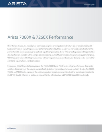
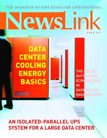
across a VXLAN connection. Networking devices carrying VXLAN-encapsulated traffic, both within the DC andacross the wide area network transport, need to be capable of supporting the resulting larger packets. If, as insome cases, some older router interfaces are incapable of supporting MTUs of greater than 1500 bytes, it may benecessary to modify the default MTU size on some end devices to ensure this limit isn’t exceeded.CONFIGURATION EXAMPLEThe following example describes a simple VXLAN data center interconnection deployment scenario, with thefollowing characteristics: Dual data centers A DCI module per site, consisting of a pair of switches configured as an MLAG pair connected to a singleLAG attached to a “downstream” switch (representing the local DC network) Parallel, point-to-point layer-3 links between adjacent MLAG members at each DC A logical VXLAN VTEP configured on each DCI MLAG pair OSPF routing between sites Two VLANs (100 & 200) to relay between sites, each mapped to a corresponding VXLAN VNI as follows:oVLAN100 mapped to VNI 10000oVLAN200 mapped to VNI 200The following diagrams show, in turn, the physical and logical topologies of this network. The relevantconfiguration file sections are also included for reference.THE PHYSICAL TOPOLOGYFigure 10 shows the physical topology used for this configuration example. All links are 10GbE in this example.Figure 10: Example DCI Solution – Physical TopologyARISTA DESIGN GUIDEDATA CENTER INTERCONNECTION WITH VXLAN14
S
ARISTA DESIGN GUIDE DATA CENTER INTERCONNECTION WITH VXLAN 6 INTRODUCING THE ARISTA NETWORKS DCI WITH VXLAN SOLUTION VXLAN was designed for the creation of logical layer-2 domains on top of an underlying IP network, initially to enable network virtualization in the data center. VXLAN ide