Transcription
Product DataWeatherMaker Single Packaged RooftopHeat Pump Units6 to 12.5 Nominal Tons50TCQ*07, 08, 12, 14Electric Cooling Rooftop Units with Heat Pump andOptional Electric Heat with Puron (R-410A) Refrigerant 2020 CarrierForm 50TCQ-7-14-02PD Rev. A
Features/BenefitsThe Carrier Packaged HeatPump rooftop unit (RTU) wasdesigned by customers forcustomers. With no-stripscrew collars, handledaccess panels, and more,we’ve made your unit easy toinstall, easy to maintain andeasy to use.Easy to installAll WeatherMaker units are field-convertible to horizontal air flow whichmakes it easy to adjust to unexpected jobsite complications. Lighter units makeeasy replacement. Carrier 6 to 12.5 ton50TCQ rooftops fit on existing Carriercurbs dating back to 1989. Also, ourlarge control box gives you room to workand room to mount Carrier accessorycontrols.Easy to maintainEasy access handles by Carrier providequick and easy access to all normallyserviced components. Our “no-strip”screw system has superior holdingpower and guides screws into positionwhile preventing the screw from stripping the unit’s metal.Easy to useThe central terminal board puts all yourconnections and troubleshooting pointsin one convenient place, standard. Mostlow voltage connections are made to thesame board and make it easy to findwhat you’re looking for and easy toaccess it. Carrier rooftops have highand low pressure switches, a filter drier,and 2-in. (51 mm) filters standard. EER up to 11.2. IEER up to 12.5 with single speedindoor fan motor and up to 12.7with 2-speed/VFD indoor fan motor. 6 - 12.5 ton units fit on existing Carrier rooftop curbs making the utilityconnections the same. This savestime and money on replacement jobs. Standardized components and layout. Standardized components andcontrols make service and stockingparts easier. Scroll compressors on all units. Thismakes service, stocking parts,replacement, and trouble-shootingeasier. Crankcase heater on all modelsprovides added protection in allapplications. Precision-sized suction line accumulator provides high reliability by preventing liquid from entering thecompressor during low ambient conditions and reverse cycle switch over. Field convertible from vertical tohorizontal airflow configuration onall models. No special kit requiredon 07-12 models. Supply duct kitrequired for 14 model only. 4-way reversing valve rapidlychanges the flow of refrigerant toquickly changeover from cooling toheating and heating to cooling. Easy-adjust, belt drive motor available on all sizes. There’s no need forfield-supplied drives or motors. Provisions for bottom or side condensate drain. Capable of thru-the-base or thruthe-curb electrical routing. Dependable time / temperaturedefrost logic provides a defrostTable of contentsFeatures/Benefits. . . . . . . . . . . . . . . . . . . . . . . . . . . . . . . . . . . . . . . . . . . . 2Model Number Nomenclature . . . . . . . . . . . . . . . . . . . . . . . . . . . . . . . . . . . 3Capacity Ratings . . . . . . . . . . . . . . . . . . . . . . . . . . . . . . . . . . . . . . . . . . . . 4Physical Data. . . . . . . . . . . . . . . . . . . . . . . . . . . . . . . . . . . . . . . . . . . . . . . 6Options and Accessories. . . . . . . . . . . . . . . . . . . . . . . . . . . . . . . . . . . . . . . 8Base Unit Dimensions . . . . . . . . . . . . . . . . . . . . . . . . . . . . . . . . . . . . . . . 12Accessory Dimensions . . . . . . . . . . . . . . . . . . . . . . . . . . . . . . . . . . . . . . . 26Performance Data . . . . . . . . . . . . . . . . . . . . . . . . . . . . . . . . . . . . . . . . . . 29Fan Data . . . . . . . . . . . . . . . . . . . . . . . . . . . . . . . . . . . . . . . . . . . . . . . . . 44Electrical Data . . . . . . . . . . . . . . . . . . . . . . . . . . . . . . . . . . . . . . . . . . . . . 52Typical Wiring Diagrams . . . . . . . . . . . . . . . . . . . . . . . . . . . . . . . . . . . . . 96Sequence of Operation. . . . . . . . . . . . . . . . . . . . . . . . . . . . . . . . . . . . . . 102Application Data . . . . . . . . . . . . . . . . . . . . . . . . . . . . . . . . . . . . . . . . . . 105Guide Specifications. . . . . . . . . . . . . . . . . . . . . . . . . . . . . . . . . . . . . . . . 1062 cycle, if needed, every 30, 60, 90,or 120 minutes and is adjustable.Single-point electrical connection.Sloped, composite drain pan won’trust and is self draining.Standardized controls and controlbox layout. Standardized components and controls make stockingparts and service easier.Clean, large, easy to use control box.Standard coils are copper round tube,aluminum plate fin with optional coilcoatings and copper fin design.Color-coded wiring.Large, laminated wiring and powerwiring drawings which are affixed tounit make troubleshooting easy.Single, central terminal board fortest and wiring connections.Fast-access, handled, panels for easyaccess to the blower and blowermotor, control box, and compressors.“No-strip” screw system guidesscrews into the panel and capturesthem tightly without stripping thescrew, the panel, or the unit.Exclusive, newly-designed indoorrefrigerant header for easier maintenance and replacement.Mechanical cooling (115 F to 25 For 46 C to –4 C) on Electromechanical (E/M) and Direct DigitalController (DDC) (PremierLink orRTU Open controller).2-in. (51 mm) disposable filters onall units.High capacity refrigerant filter drieron each circuit.High pressure, loss of charge, andfreeze switches provide higher protection for the unit refrigeration system.
Model number nomenclature Staged Air Volume (SAV ) fan speed system utilizes aVariable Frequency Drive (VFD) to automatically adjustthe indoor fan motor speed between cooling stages.Available on single stage cooling model 07 and 2-stagecooling models, 08-14 with electro-mechanical controlsor RTU Open controller. Note that SAV is required onall units for installation in the United States as per theDepartment of Energy (DOE) efficiency standard of2018.50TCQ MODEL NUMBER NOMENCLATUREPosition:12345678Example:50TCQD089 10 11 12 13 14 15 16 17 181 A 6 – 0 B 2 A 0ASeries - WeatherMaker 50TC - Packaged RooftopPackaging0 Standard1 LTLQ Heat PumpRefrig. Systems OptionsA One Stage Cooling ModelsD Two Stage Cooling ModelsCooling Tons07 - 6 ton08 - 7.5 ton09 - 8.5 ton12 - 10 ton14 - 12.5 tonSensor OptionsA NoneB RA Smoke DetectorC SA Smoke DetectorD RA SA Smoke DetectorE CO2F RA Smoke Detector and CO2G SA Smoke Detector and CO2H RA SA Smoke Detector and CO2J Condensate Overflow SwitchK Condensate Overflow Switch and RA Smoke DetectorsL Condensate Overflow Switch and RA and SA Smoke DetectorsIndoor Fan Options1 Standard Static Option - Belt Drive2 Medium Static Option - Belt Drive3 High Static Option - Belt DriveC High Static Option with High Efficiency Motor- Belt Drive(size 14 only)Coil Options - Round Tube/Plate Fin Condenser Coil(Outdoor – Indoor – Hail Guard)A Al/Cu – Al/CuB Precoat Al/Cu – Al/CuC E-coat Al/Cu – Al/CuD E-coat Al/Cu – E-coat Al/CuE Cu/Cu – Al/CuF Cu/Cu – Cu/CuM Al/Cu – Al/Cu – Louvered Hail GuardN Precoat Al/Cu – Al/Cu – Louvered Hail GuardP E-coat Al/Cu – Al/Cu – Louvered Hail GuardQ E-coat Al/Cu – E-coat Al/Cu – Louvered Hail GuardR Cu/Cu – Al/Cu – Louvered Hail GuardS Cu/Cu – Cu/Cu – Louvered Hail GuardElectrical OptionsA NoneC Non-Fused DisconnectD Thru-The-Base ConnectionsF Non-Fused Disconnect andThru-The-Base ConnectionsG 2-Speed Indoor Fan Controller (VFD)J 2-Speed Indoor Fan Controller (VFD)and Non-Fused DisconnectK 2-Speed Indoor Fan Controller (VFD)and Thru-The-Base ConnectionsM 2-Speed Indoor Fan Controller (VFD)with Non-Fused Disconnect andThru-The-Base ConnectionsService Options0 None1 Unpowered Convenience Outlet2 Powered Convenience Outlet3 Hinged Access Panels4 Hinged Access Panels andUnpowered Convenience Outlet5 Hinged Panels andPowered Convenience OutletIntake / Exhaust OptionsA NoneB Temperature Economizer w/ Barometric ReliefF Enthalpy Economizer w/ Barometric ReliefK 2-Position DamperU Temperature Ultra Low Leak Economizer withBarometric ReliefW Enthalpy Ultra Low Leak Economizer withBarometric ReliefBase Unit Controls0 Electro-mechanical Controls can be used with W7212EconoMi er IV (Non-Fault Detection and Diagnostic1 PremierLinkTM Controller2 RTU Open Multi-Protocol Controller6 Electro-mechanical w/ 2-speed fan and W7220Economizer controller Controls. Can be used withW7220 EconoMi er X (with Fault Detection andDiagnostic)Design Revision– Factory Design RevisionVoltage1 575/3/605 208-230/3/606 460/3/603
Capacity ratingsAHRI RATINGS – COOLING .88.810.513.311.111.211.211.010.6IEER WITHSINGLE SPEEDINDOORMOTOR12.512.212.211.410.7IEER WITH2-SPEEDINDOORMOTOR12.712.512.512.512.0AHRI RATINGS – HEATING MODE50TCQA07D08D09D12D14HEATINGLOW AT 17 F (–8 C) AMBIENTCAPACITY 6,0002.05LEGENDAHRI— Air-Conditioning, Heating and Refrigeration InstituteASHRAE — American Society of Heating, Refrigerating and AirConditioning EngineersCOP— Coefficient of PerformanceEER— Energy Efficiency RatioIECC— International Energy Conservation CodeIEER— Integrated Energy Efficiency Ratio4HEATINGHIGH AT 47 F (8 C) AMBIENTCAPACITY 142,0003.20NOTES:1. Rated and certified under AHRI Standard 210/240 or 340/360, asappropriate.2. Ratings are based on:Cooling Standard: 80 F (27 C) db, 67 F (19 C) wb indoor airtemp and 95 F db outdoor air temp.IEER Standard: A measure that expresses cooling part-load EERefficiency for commercial unitary air conditioning and heat pumpequipment on the basis of weighted operation at variable loadcapacities.3. All 50TCQ units meet the DOE-2018 (Department of Energy),ASHRAE 90.1-2016 and IECC-2015 minimum efficiency requirements when equipped with the SAV (staged air volume) option.
MINIMUM - MAXIMUM AIRFLOWS (CFM) COOLING AND ELECTRIC 03750COOLINGMINIMUMMINIMUM2-SPEED2-SPEEDFAN MOTORFAN MOTOR(AT HIGH SPEED) (AT LOW TRIC 002250*2250*3000375030003750425050006250*Minimum electric heat CFM exceptions (see table below):UNITUNIT VOLTAGEHEATER kWUNIT CONFIGURATION50TCQD0850TCQD0957517.034.0Horizontal orVerticalREQUIREDMINIMUM CFM28002350SOUND PERFORMANCE .085.2OUTDOOR SOUND 85.983.081.680.378.077.0LEGENDdB — DecibelNOTES:1. Outdoor sound data is measured in accordance with AHRI standard 270.2. Measurements are expressed in terms of sound power. Do notcompare these values to sound pressure values because 3.7800062.467.466.575.568.9pressure accounts for specific environmental factors which do notmatch individual applications. Sound power values are independent of the environment and therefore more accurate.3. A-weighted sound ratings filter out very high and very low frequencies, to better approximate the response of an “average” humanear. A-weighted measurements for Carrier units are taken inaccordance with AHRI Standard 270.5
Physical data50TCQ*07 PHYSICAL DATA50TCQA07REFRIGERATION SYSTEM# Circuits / # Comp. / TypeR-410A charge A/B (lbs - oz)oil A/B (oz)Metering deviceHigh-pressure trip/reset (psig)Low-pressure trip/reset (psig)1 / 1 / Scroll17 - 10 / 56 / Accutrol630 / 50527 / 44EVAP. COILMaterialCoil typeRows / FPITotal face area (ft2)Condensate drain conn. sizeCu / AlRTPF4/ 157.33/ -in.43/ -in.8EVAP. FAN AND MOTORStandard Static3 phaseMedium Static3 phaseHigh Static3 phaseMotor qty / drive typeMax BHPRPM rangeMotor frame sizeFan qty / typeFan diameter x length (in.)Motor qty / drive typeMax BHPRPM rangeMotor frame sizeFan qty / typeFan diameter x length (in.)Motor qty / drive typeMax BHPRPM rangeMotor frame sizeFan qty / typeFan diameter x length (in.)1 / Belt1.5878-1192561 / Centrifugal10 x 101 / Belt2.91066-1380561 / Centrifugal10 x 101 / Belt2.91208-1550561 / Centrifugal10 x 10COND. COILMaterialCoil typeRows / FPITotal face area (ft2)Cu / AlRTPF2 / 1721.33/ -in.8COND. FAN / MOTORQty / motor drive typeMotor HP / RPMFan diameter (in.)1 / direct/ 1100221/4FILTERSRA Filter # / size (in.)OA inlet screen # / size (in.)64 / 16 x 16 x 21 / 20 x 24 x 1
50TCQ*08-14 PHYSICAL DATA50TCQD0850TCQD0950TCQD1250TCQD142 / 2 / Scroll10 - 3 / 10 - 342 / 42Accutrol630 / 50527 / 442 / 2 / Scroll11 - 2 / 11 - 242 / 42Accutrol630 / 50527 / 442 / 2 / Scroll15 - 1 / 14 - 1—Accutrol630 / 50527 / 442 / 2 / Scroll14 - 8 / 13 - 8—Accutrol630 / 50527 / 44REFRIGERATION SYSTEM# Circuits / # Comp. / TypeR-410A charge A/B (lbs - oz)oil A/B (oz)Metering deviceHigh-pressure trip/reset (psig)Loss of charge pressure trip/reset (psig)EVAP. COILMaterialCoil typeRows / FPITotal face area (ft2)Condensate drain conn. sizeCu / AlRTPF3 / 1511.13/ -in.43/ -in.8Cu / AlRTPF4 / 1511.13/ -in.43/ -in.8Cu / AlRTPF4 / 1511.13/ -in.43/ -in.8Cu / AlRTPF3 / 1517.53/ -in.43/ -in.8EVAP. FAN AND MOTORStandard Static3 phaseMedium Static3 phaseHigh Static3 phaseHigh StaticHigh Efficiency3 phaseMotor qty / drive typeMax BHPRPM rangeMotor frame sizeFan qty / typeFan diameter x length (in.)Motor qty / drive typeMax BHPRPM rangeMotor frame sizeFan qty / typeFan diameter x length (in.)Motor qty / drive typeMax BHPRPM rangeMotor frame sizeFan qty / typeFan diameter x length (in.)Motor qty / drive typeMax BHPRPM rangeMotor frame sizeFan qty / typeFan diameter x length (in.)1 / Belt1.2460-652561 / Centrifugal15 x 151 / Belt2.9591-838561 / Centrifugal15 x 151 / Belt2.9838-1084561 / Centrifugal15 x 15——————1 / Belt1.2460-652561 / Centrifugal15 x 151 / Belt2.9591-838561 / Centrifugal15 x 151 / Belt2.9838-1084561 / Centrifugal15 x 15——————1 / Belt1.7591-839561 / Centrifugal15 x 151 / Belt2.8733-949561 / Centrifugal15 x 151 / Belt4.0838-1084561 / Centrifugal15 x 15——————1 / Belt2.9507-676561 / Centrifugal18 x 181 / Belt2.9634-833561 / Centrifugal18 x 18——————1 / Belt6.5 / 6.9 / 7.0 / 8.3792-971S184T1 / Centrifugal18 x 18COND. COILMaterialCoil typeRows / FPITotal face area (ft2)Cu / AlRTPF2 / 1725.13/ -in.8Cu / AlRTPF2 / 1725.13/ -in.8Cu / AlRTPF3 / 1725.13/ -in.8Cu / AlRTPF2 / 1736.13/ -in.8COND. FAN / MOTORQty / motor drive typeMotor HP / RPMFan diameter (in.)2 / direct/ 1100221/42 / direct/ 1100221 / direct1 / 1175301/43 / direct/ 1100221/4FILTERSRA Filter # / size (in.)4 / 20 x 20 x 24 / 20 x 20 x 24 / 20 x 20 x 2OA inlet screen # / size (in.)1 / 20 x 24 x 11 / 20 x 24 x 11 / 20 x 24 x 16 / 18 x 24 x 22 / 24 x 27 x 1(Vertical)1 / 30 x 39 x 1(Horizontal)7
Options and accessoriesFACTORY-INSTALLED OPTIONS AND FIELD-INSTALLED ACCESSORIESCATEGORYITEMThru-the-base electrical connectionsDisconnect switch bracket (available 14 size only)Supply duct cover (available 14 size only)Cu/Cu indoor and/or outdoor coilsCoil OptionsPre-coated outdoor coilsPremium, E-coated outdoor coilsCondenser Protection Condenser coil hail guard (louvered design)Thermostats, temperature sensors, and subbasesPremierLink DDC communicating controller1RTU Open multi-protocol controllerSmoke detector (supply and/or return air)ControlsHorn/Strobe annunciator2Time Guard II compressor delay control circuitPhase monitorCondensate overflow switchEconoMi er IV for electro-mechanical controls - Non FDD, (Low leak air damper models)3EconoMi er 2 for DDC controls, complies with FDD (Low Leak and Ultra Low Leak airdamper models)4 6EconoMi erX for electro-mechanical controls, complies with FDD (Low Leak and Ultra LowEconomizersLeak air damper controls)3and Outdoor AirMotorized 2 position outdoor air damper1DampersManual outdoor air damper (25% and 50%)1Barometric relief5Power exhaustSingle dry bulb temperature sensors6Differential dry bulb temperature sensors6Economizer Sensors Single enthalpy sensors6and IAQ DevicesDifferential enthalpy sensors6CO2 sensor (wall, duct, or unit mounted)6Winter start kitElectric resistance heatersElectric HeatSingle point kitHinged access panelsMultiple motor and belt drive packagesIndoor MotorStaged air volume (SAV ) fan speed system with VFD controller (for units with electricaland Drivemechanical and RTU Open controller only)7Display kit for SAV system with VFDLow Ambient Control Motormaster head pressure controller8Convenience outlet (powered)PowerConvenience outlet (unpowered): 15 amp factory-installed, 20 amp field-installedOptionsNon-fused disconnect9Roof curb 14-in. (356 mm)Roof CurbsRoof curb 24-in. (610 mm)CabinetFACTORYFIELDINSTALLED XXXXXXXXXXXXXXXXXXXXXXXXNOTES:1. Not available with SAV.2. Requires a field-supplied 24V transformer for each application. See price pages for details.3. FDD (Fault Detection and Diagnostic) capability per California Title 24 section 120.2.4. Models with RTU Open DDC controls comply with California Title 24 Fault Detection and Diagnostic (FDD). PremierLink is not FDD.5. Included with economizer.6. Sensors for optimizing economizer performance.7. SAV is required on all units for installation in the United States as per the Department of Energy (DOE) efficiency standard of 2018.8. See application data for assistance.9. Available on size 07-12 units with MOCPs of 80 amps or less and on size 14 units with MOCPs of 100 amps or less.8XXX
EconomizerPower Exhaust Pressure ReliefEconomizers can reduce operating costs. They bring infresh, outside air for ventilation; and provide cool, outsideair to cool your building. This is the preferred method oflow ambient cooling. When coupled to CO2 sensors, economizers can limit the ventilation air to only that amountrequired.Economizers are available, installed and tested by the factory, with either enthalpy or dry bulb temperature inputs.There are also models for electro-mechanical as well asdirect digital controllers. Additional sensors are available asaccessories to optimize the economizers.Economizers include gravity controlled, barometric reliefwhich equalizes building pressure and ambient air pressures. This can be a cost effective solution to prevent building pressurization. Economizers are available in ultra lowleak and low leak versions.Superior internal building pressure control. This fieldinstalled accessory may eliminate the need for costly, external pressure control fans.CO2 SensorThe CO2 sensor works with the economizer to intake onlythe correct amount of outside air for ventilation. As occupants fill your building, the CO2 sensor detects their presence through increasing CO2 levels, and opens theeconomizer appropriately.When the occupants leave, the CO2 levels decrease, andthe sensor appropriately closes the economizer. This intelligent control of the ventilation air, called Demand Controlled Ventilation (DCV), reduces the overall load on therooftop, saving money.Smoke DetectorsTrust the experts. Smoke detectors make your applicationsafer and your job easier. Carrier smoke detectors immediately shut down the rooftop unit when smoke is detected.They are available, installed by the factory, for supply air,return air, or both.Louvered Hail GuardsSleek, louvered panels protect the condenser coil from haildamage, foreign objects, and incidental contact.Convenience Outlet (powered or un-powered)Reduce service and/or installation costs by including a convenience outlet in your specification. Carrier will install thisservice feature at our factory. Provides a convenient,15 amp, 115v GFCI receptacle with “Wet in Use” cover.The “powered” option allows the installer to power theoutlet from the line side of the disconnect as required bycode. The “unpowered” option is to be powered from aseparate (non-unit) 115/120v power source. The unpowered convenience outlet is available as a 15 amp factoryinstalled option or a 20 amp field-installed accessory.The 20 amp unpowered convenience outlet kit provides aflexible installation method which allows code compliancefor height requirements of the GFCI outlet from the finished roof surface as well as the capability to relocate theoutlet to a more convenient location, if necessary.Non-Fused DisconnectThis OSHA-compliant, factory-installed, safety switchallows a service technician to locally secure power to therooftop.When selecting a factory-installed non-fused disconnect,note they are sized for unit as ordered from the factory.The sizing of these does not accommodate any powerexhaust devices, etc.PremierLink ControllerThis CCN controller regulates your rooftop’s performanceto tighter tolerances and expanded limits, as well as facilitates zoning systems and digital accessories. It also unitesyour Carrier HVAC equipment together on one, coherentCCN network. The PremierLink controller can be factoryinstalled, or easily field-installed. Not available with StagedAir Volume (SAV ) fan speed system.RTU Open, Multi-protocol ControllerConnect the rooftop to an existing BAS without needingcomplicated translators or adapter modules using the RTUOpen controller. This new controller speaks the 4 mostcommon building automation system languages (BACnet1,Modbus2, N2, and LonWorks3) Use this controller whenyou have an existing BAS.Time Guard II Control CircuitThis accessory protects the compressor by preventingshort-cycling in the event of some other failure, preventsthe compressor from restarting for 30 seconds after stopping. Not required with PremierLink controller, RTU Opencontroller, or authorized commercial thermostats.Filter or Fan Status SwitchesUse these differential pressure switches to detect a filterclog or indoor fan motor failure. When used in conjunctionwith a compatible unit controller/thermostat, the switcheswill activate an alarm to warn the appropriate personnel.Motorized 2-Position DamperThe Carrier 2-position, motorized outdoor air damperadmits up to 100% outside air. Using gear-driven technology, the 2-position damper opens to allow ventilation airand closes when the rooftop stops, stopping unwantedinfiltration. Not available with Staged Air Volume (SAV) fanspeed system.Manual OA DamperManual outdoor air dampers are an economical way tobring in ventilation air. The dampers are available in 25%and 50% versions. Not available with Staged Air Volume(SAV) system.Staged Air Volume (SAV) Indoor Fan SpeedSystemCarrier’s SAV fan speed system saves energy and installation time by utilizing a Variable Frequency Drive (VFD) toautomatically adjust the indoor fan motor speed in sequencewith the units cooling operation. Per ASHRAE 90.1-2016and IECC4-2015 standards, during the first stage of coolingoperation the VFD will adjust the fan motor to provide 66%of the total cfm established for the unit. When a call for thesecond stage of cooling is required, the VFD will allow thetotal cfm for the unit established (100%). During the heatingmode the VFD will allow total design cfm (100%) operationand during the ventilation mode the VFD will allow operation to 66% of total cfm.1. BACnet is a registered trademark of ASHRAE (American Society ofHeating, Refrigerating and Air-Conditioning Engineers).2. Modbus is a registered trademark of Schneider Electric.3. LonWorks is a registered trademark of Echelon Corporation.4. IECC is a registered trademark of International Code Council, Inc.9
Options and accessories (cont)Compared to single speed indoor fan motor systems, Carrier’s SAV system can save substantial energy, 25% , versus single speed indoor fan motor systems.IMPORTANT: Data based on 0.10 ( /kWh) in an officeapplication utilizing Carrier’s HAP 4.6 simulation software program.The VFD used in Carrier’s SAV system has soft start capabilities to slowly ramp up the speeds, thus eliminating anyhigh inrush air volume during initial start-up. It also hasinternal over current protection for the fan motor and afield-installed display kit that allows adjustment and indepth diagnostics of the VFD.This SAV system is available on models with electricalmechanical or RTU Open, Multi Protocol controls. Bothspace sensor and conventional thermostats controls can beused to provide accurate control in any application.The SAV system is very flexible for initial fan performanceset up and adjustment. The standard factory shipped VFDis pre-programmed to automatically stage the fan speedbetween the first and second stage of cooling. The unit fanperformance static pressure and cfm can be easily adjustedusing the traditional means of pulley adjustments. Theother means to adjust the unit static and cfm performanceis to utilize the field-installed display kit and adjust the frequency and voltage in the VFD to required performancerequirements. In either case, once set up, the VFD willautomatically adjust the speed between the cooling stageoperations.Staged Air Volume (SAV) — Variable Frequency Drive(VFD) HP Rating50TCQ070809121410Voltage208/230, 460, 575208/230, 460575208/230460, 575208/230, 460, 575208/230, 460575208/230, 460, 575208/230, 460, 575208/230, 460, 575208/230460, 575208/230, 460, 575208/230460, 575208/230, 460, 575208/230, 460575208/230460, 575208/230, 460, 575Static .53.05.03.05.07.5Motormaster Head Pressure ControllerThe Motormaster motor controller is a low ambient, headpressure controller kit that is designed to maintain theunit’s condenser head pressure during periods of low ambient cooling operation. This device should be used as analternative to economizer free cooling when economizerusage is either not appropriate or desired. The Motormaster controller will either cycle the outdoor fan motors oroperate them at reduced speed to maintain the unit operation, depending on the model.The Motormaster controller allows cooling operation downto –20 F (–29 C) ambient conditions.Alternate Motors and DrivesSome applications need larger horsepower motors, someneed more airflow, and some need both. Regardless of thecase, your Carrier expert has a factory-installed combination to meet your application. A wide selection of motorsand pulleys (drives) are available, factory-installed, to handle nearly any application.Thru-the-Base ConnectionsThru-the-base connections, available as either an accessoryor as a factory option, are necessary to ensure proper connection and seal when routing wire and piping through therooftop’s basepan and curb. These couplings eliminateroof penetration and should be considered for gas lines,main power lines, as well as control power.Disconnect Switch BracketProvides a pre-engineered and sized mounting bracket forapplications requiring a unit mounted fused disconnect ofgreater than 100 amps. Bracket assures that no damagewill occur to coils when mounting with screws and otherfasteners. (Size 14 only.)Supply Duct CoverThis supply duct cover is required when field converting thefactory standard vertical duct supply to horizontal duct supply configuration. One is required per unit. (Size 14 only.)Electric HeatersCarrier offers a full line of field-installed accessory heaters.The heaters are very easy to use and install. All are preengineered and certified.Thru-the-Base ConnectionsThru-the-base connections, available as either an accessoryor as a factory option, are necessary to ensure proper connection and seal when routing wire and piping through therooftop’s basepan and curb. These couplings eliminateroof penetration and should be considered for gas lines,main power lines, as well as control power.
50TCQ OPTION/ACCESSORY WEIGHTSOPTION/ACCESSORYPower Exhaust — VerticalPower Exhaust — HorizontalEconoMi er (IV, X or 2)Two Position DamperManual DampersHail Guard (louvered)Cu/Cu Condenser CoilCu/Cu Cond. and Evaporator CoilsRoof Curb (14-in. curb)Roof Curb (24-in. curb)CO2 sensorElectric HeaterSingle Point KitOptional Indoor Motor / DriveMotormaster ControllerReturn Smoke DetectorSupply Smoke DetectorNon-Fused DisconnectPowered Convenience OutletNon-Powered Convenience OutletEnthalpy SensorDifferential Enthalpy SensorSAV System with — Not availableNOTE: Where multiple variations are available, the heaviest combination is listed.11
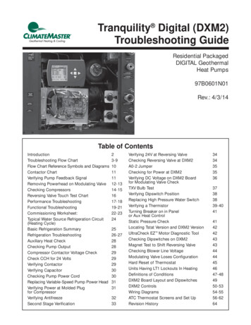
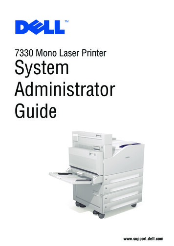
Base unit dimensions12DIMENSIONS OF 50TCQ*07 UNITS BUILT ON AND AFTER 4/15/2019
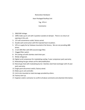
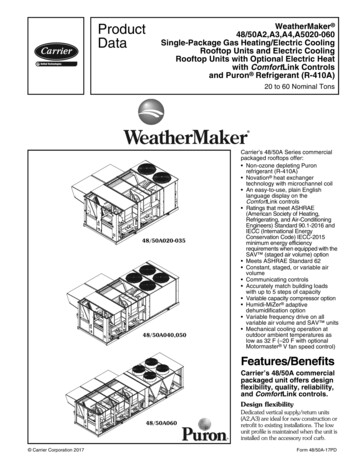
DIMENSIONS OF 50TCQ*07 UNITS BUILT PRIOR TO 4/15/201913
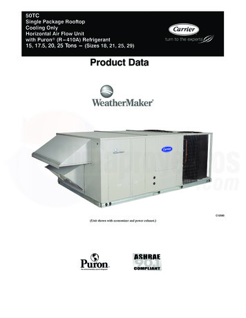
Base unit dimensions (cont)1450TCQ*07 CORNER WEIGHTS AND CLEARANCES
50TCQ*07 BASE RAIL DETAILS15
Base unit dimensions (cont)1650TCQ*07 THRU-THE-BASE CHARTS
50TCQ*08-09 UNIT DIMENSIONS17
Base unit dimensions (cont)1850TCQ*08-09 UNIT DIMENSIONS (cont)
50TCQ*08-09 SERVICE CLEARANCESCDBLOCATIONABCDDIMENSION48-in. (1219 mm)18-in. (457 mm)18-in. (457 mm)12-in. (305 mm)42-in. (1067 mm)36-in. (914 mm)Special36-in. (914 mm)18-in. (457 mm)42-in. (1067 mm)36-in. (914 mm)ACONDITIONUnit disconnect is mounted on panelNo disconnect, convenience outlet optionRecommended service clearanceMinimum clearanceSurface behind servicer is grounded (e.g., metal, masonry wall)Surface behind servicer is electrically non-conductive (e.g., wood, fiberglass)Check for sources of flue products within 10 ft (3 m) of unit fresh air intake hoodSide condensate drain is usedMinimum clearanceSurface behind servicer is grounded (e.g., metal, masonry wall, anoth
4 LEGEND NOTES: 1. Rated and certified under AHRI Standard 210/240 or 340/360, as appropriate. 2. Ratings are based on: Cooling Standard: 80 F (27 C) db, 67 F (19 C) wb indoor air temp and 95 F db outdoor air temp.