Transcription
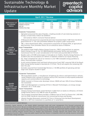
ANALYSIS OF SOLAR THERMAL POWER PLANTS WITHTHERMAL ENERGY STORAGE ANDSOLAR-HYBRID OPERATION STRATEGYStefano Giuliano1, Reiner Buck1 and Santiago Eguiguren11German Aerospace Centre (DLR), ), Institute of Technical Thermodynamics, Solar Research,Pfaffenwaldring 38-40, 70569 Stuttgart, Germany, 49-711-6862-633, stefano.giuliano@dlr.deAbstractSelected solar-hybrid power plants for operation in base-load as well as mid-load were analyzed regardingsupply security (due to hybridization with fossil fuel) and low CO2 emissions (due to integration of thermalenergy storage). The power plants were modeled with different sizes of solar fields and different storagecapacities and analyzed on an annual basis. The results were compared to each other and to a conventionalfossil fired combined cycle in terms of technical, economical and ecological figures.The results of this study show that in comparison to a conventional fossil fired combined cycle the potentialto reduce the CO2 emissions is high for solar thermal power plants operated in base-load, especially withlarge solar fields and high storage capacities. However, for dispatchable power generation and supplysecurity it is obvious that in any case a certain amount of additional fossil fuel is required. No analyzed solarhybrid power plant shows at the same time advantages in terms of low CO2 emissions and low LEC. Whilepower plants with solar-hybrid combined cycle (SHCC , Particle-Tower) show interesting LEC, the powerplants with steam turbine (Salt-Tower, Parabolic Trough, CO2-Tower) have low CO2 emissions.Keywords: solar thermal power plant, solar-hybrid power plant, solar tower plant, parabolic trough.1. IntroductionSolar thermal power plants can guarantee supply security by integration of thermal energy storages and/ or byusing a solar fossil hybrid operation strategy. Only few technologies among the renewables offer this baseload ability. Therefore it is predicted that they will have a significant market share of the future energy sector.The sun is an intermittent source of energy. Solar power plants that are operated with a solar-only operationstrategy and use thermal energy storages to extend the operation to hours when the sun does not shine cannotentirely provide power on demand and account at the same time for economical aspects. Therefore thosesolar power plants do not have a real ability for base-load and the utilities have to provide backup powerfrom conventional fossil fired power plants. This situation can be overcome by the use of additional fossilfuel to generate the heat in a solar-hybrid power plant.However, the transition from a solar-only power plant to a solar-hybrid power plant incorporates someconflicts. While the economy of the power plant is improved as the annual utilization of the plant isincreased, the emission of green house gases (e.g. CO2) is also increased. Is there an optimum existing for thesolar share and the share of hybridization to account for economical and ecological aspects? What is theinfluence of increasing fuel prices and increasing carbon trading costs coupled with high power blockefficiencies?In this study five different types of solar-hybrid power plants with different sizes of solar fields and differentstorage capacities are modeled and analyzed on an annual basis. The results of the solar-hybrid power plantsare compared to each other and to a conventional fossil fired combined cycle power plant in terms oftechnical, economical and ecological figures. Beside of state of the art solar power plant concepts(Fig. 1b and c) also new and innovative solar power plant concepts (Fig. 1a, d and e) were analyzed in detailfor this study.
a) Solar-hybrid Combined Cycle (SHCC )Solar tower with solar-hybrid combined cycle and pressurizedsolid media thermal energy storageReceiverb) Salt-TowerSolar tower with steam turbine and molten salt as heat transfermedium and for thermal energy storageBurnerHRSGVR RSteam turbineStorageGGGas turbineCondenserSolar fieldSolar towerc) Parabolic TroughParabolic Trough with steam turbine and with thermal oil as heattransfer medium and molten salt thermal energy storaged) CO2-TowerSolar tower with steam turbine and pressurized gas receiver(CO2) and pressurized solid media thermal energy storagee) Particle-TowerSolar tower with solar-hybrid combined cycle and with solid mediaparticles as heat transfer medium and for thermal energy storagef) Combined Cycle (CC)Conventional fossil-fired combined cycle as reference plantFig. 1. Analyzed solar-hybrid power plants.2. Solar-hybrid power plantsFor this study the solar-hybrid power plants shown in Fig. 1 were designed and modeled for a site inNorthern Africa (Hassi R’Mel, Algeria) for a power level of 30 MWel with dry cooling towers. Due to theintegrated fossil burner each analyzed solar-hybrid power plant can be operated in solar-only, fossil-only orsolar-hybrid mode. To increase the solar share of the plant a thermal energy storage is used.All solar-hybrid power plants were modeled with different sizes of solar fields and different storagecapacities. Therefore for a solar field with solar multiple 1 (SM1)1 no storage is used, for SM2 a storagecapacity of 7.5h (i.e. 7.5h of nominal load operation at design point conditions) and for SM3 a storagecapacity of 15h is used. It is clear that this combination of SM and storage capacity is not optimal e.g. for thelowest electricity generation cost (levelized electricity cost or LEC). But for this study this combination isappropriate to perform the intended comparison with equal boundary conditions.1A solar field with SM1 can deliver the required design thermal power to run the power plant on nominal load at design pointconditions.
Following each solar-hybrid power plant is briefly described and some specifications are given. Further detailspecifications as well as the definition of the design point conditions are summarized in Table 1 in the annex.2.1. Solar-hybrid Combined Cycle (SHCC )The solar-hybrid combined cycle is a solar tower power plant. It consists of a heliostat field (solar field), asolar receiver mounted on top of a tower and a gas turbine that is modified for solar-assisted operation. Insolar-hybrid combined cycles the concentrated solar power is used to heat the pressurized air before enteringthe combustion chamber of the gas turbine cycle of a combined cycle. The solar heat can therefore beconverted with the high thermal efficiency of combined gas turbine cycles. Fig. 1a shows the flow schematicof this system. The combustion chamber closes the temperature gap between the receiver outlet temperature(850 C at design point) and the turbine inlet temperature ( 1100 C) and provides constant turbine inletconditions despite fluctuating solar input. For this study a model of a solarized gas turbine of the MANTHM1304-12 with bottoming steam cycle was used [1]. Because of size dependency of steam turbineefficiency and costs a 2 1 combined cycle with two gas turbines and one steam turbine was chosen in theSHCC project co-founded by the German BMU.The pressurized air in this system is sequentially heated in two receivers. In the low temperature receiver,which is a cavity receiver with metal tubes the air is heated up to 650 C. In the following pressurizedvolumetric air receiver for high temperatures the air is heated up to 850 C and then led to the combustionchamber of the gas turbine. This receiver concept was already successfully tested in the SOLGATE project[2]. The solar share at design point condition for this system is about 60%. Generally the pre-heating of theair could be done up to about 1000 C, what would increase the solar share. For this study a pressurized solidmedia thermal energy storage (TES) was used in addition to the layout in [1]. The gross efficiency at designpoint conditions of this dry cooled 30 MWel power block is 46.4%.2.2. Salt-TowerThe Salt-Tower is a solar tower power plant with a steam turbine and molten salt as heat transfer medium(HTF), which is also used for thermal energy storage. This system is mainly based on the Solar Two powerplant [3]. Fig. 1b shows the flow schematic of this system. The fossil burner allows an operation of the plantin solar-hybrid or fossil-only mode (storage bypass not shown in the schematic). Molten salt at 290 C ispumped out of a “cold” storage tank to the external receiver on top of a tower where it is heated to 565 C anddelivered to a “hot” storage tank. The hot salt is then extracted for the generation of 552 C/ 126bar steam inthe steam generator. The steam powers the turbine to generate electricity. The steam turbine is designed as areheat turbine with several feed-water pre-heaters to allow a gross efficiency of 42.5% at design pointconditions. The solar share at design point is 100%.2.3. Parabolic TroughThe Parabolic Trough power plant for this study is mainly based on the commercial Andasol 1 plant that wasconnected to the Spanish grid at the end of 2008. The layout was scaled to a power level of 30 MWel anddesigned for the operation with dry cooling towers. The fossil burner has unlike the Andasol 1 plant theability to run the plant on full load with fossil-only mode. Fig. 1c shows the flow schematic of this system.Thermal oil is used as HTF in the collector field. This HTF transfers the heat collected in the solar field viaheat exchangers either to a conventional water steam cycle or to the molten salt storage system. If not enoughsolar energy for solar operation of the power block is available, the HTF can be heated from the storage orthe fossil burner and transfer its heat to the water steam cycle. The HTF temperature in the cold headers is293 C and in the hot headers 393 C. The steam turbine has steam parameters of 371 C/ 100bar and isdesigned as reheat turbine with several feed-water pre-heaters. The gross efficiency at design pointconditions of the power block is 37.2%. The solar share at design point is 100%.2.4. CO2-TowerThe CO2-Tower is a solar tower power plant with a steam turbine, a pressurized gas receiver and apressurized solid media thermal energy storage. Fig. 1d shows the flow schematic of this system. CO2 is usedas HTF, which is heated up in the cavity receiver with metal tubes on top of a tower from 310-600 C. The
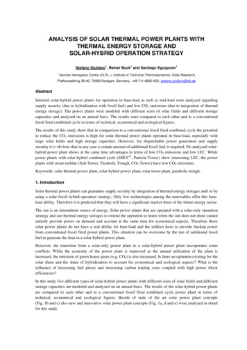
hot pressurized CO2 is then used for generation of 570 C/ 126bar steam in the steam generator and/ or to loadthe TES. The steam powers the turbine to generate electricity. The fossil burner allows an operation of theplant in solar-hybrid or fossil-only mode. The steam turbine is designed as reheat turbine with several feedwater pre-heaters to allow a gross efficiency of 43.0% at design point conditions. The solar share at designpoint is 100%.The TES is based on the actual development of the advanced adiabatic compressed air energy storagetechnology [4]. Therefore, like for the AA-CAES application, a pressure of 65bar was chosen for the HTFcircuit. Generally several pressurized gases like air, helium, nitrogen, etc. could be used. CO2 was chosen forthis application because of its interesting thermophysical properties allowing low pressure losses andtherefore low parasitic consumption. However, the pressure of the system is an optimization parameter whatshould be optimized more in detail for this system in a subsequent study.2.5. Particle-TowerThe Particle-Tower is a solar tower with a combined cycle and with solid media particles as heat transfermedium and for thermal energy storage. This is one of several possible systems for the integration of hightemperature heat from particle receivers that are currently assessed at DLR. Fig. 1e shows the flow schematicof this system. Particles are pumped out of a “cold” storage tank at 360 C to the direct contact particlereceiver on top of a tower where they are heated to 1000 C and delivered to a “hot” storage tank. In the directcontact heat exchanger (having an internal lock system for pressure balance and filters) the pressurized air isheated up to about 995 C before entering the combustion chamber of the gas turbine cycle of a combinedcycle. The combustion chamber closes the temperature gap to the turbine inlet temperature ( 1100 C). Atdesign point the solar share is about 80% and the gross efficiency of the power block is 46.4%. In this studythe same combined cycle like for the SHCC power plant was used.2.5. Combined Cycle (CC)The combined cycle (CC) is a conventional fossil-fired combined-cycle that is used as reference plant. Fig. 1fshows the flow schematic of this system. This combined cycle was modeled with a Siemens-WestinghouseV64.3A gas turbine and a bottoming steam cycle. In contrast to the solar-hybrid power plants the power levelof this power plant is about three times bigger. The gross design power is about 95 MWel. The grossefficiency at design point conditions of the dry cooled power block is 51.7%.3. Methodology for System Simulation and Economic AssessmentFor design optimization and annual performance prediction of the analyzed solar-hybrid power plantsdifferent software tools were used. Fig. 2a shows the work flow and the interaction of the used software toolsHFLCAL, Ebsilon and Excel .For the layout, the optimization and the simulation of operation of the selected power plants the commercialsoftware Ebsilon was used. The layout of cost optimized solar fields for solar towers was done withHFLCAL software [5]. For the layout of the solar fields for parabolic troughs the new solar library ofEbsilon was used. To allow the calculation of solar-hybrid power plants over a full year with hourly timeseries an interface was adapted for this study in Excel . For each hour of a year the performance of the plantwas calculated, for the hourly values of the solar irradiation (DNI), the actual weather conditions(temperature, pressure) as well as the solar position angles according to the geographic location of the siteand the time in the year. Additionally the operation strategy was modeled in detail to account on the severaloperation modes during solar mode, storage mode, hybrid (fossil) mode and mixed mode. Fig. 2b shows thegeneral schematic for the operational strategy what needs to be adapted and modeled for each solar-hybridpower plant individually [6]. For this study the power plants were always in their possible full load during theoperating time, no specific load characteristic is followed.The analysis for this study was carried out for two different load situations: 1. operating time from 0-24h,which is representing base-load operation and 2. from 6-22h, which is representing mid-load operation. Thismeans that the power plants in base-load are operated 8760 h/a and the ones in mid-load 6205 h/a.
a) Work flow of simulation softwareb) Operation mode and operational strategyFig. 2. Methodology for system simulation.The economic assessment was made to obtain the LEC for the entire plant as well as the solar LEC (i.e. theeffective cost of the electricity produced by the solar contribution [7]). The main task of the economicassessment was to elaborate the differences between the solar-hybrid power plants to each other and to aconventional reference fossil-fired combined cycle. The essential figure of merit is the LEC which iscalculated according to a simplified IEA method [8]. This approach is kept simple, but it appears to beappropriate to perform the relative comparison necessary to quantify the impact of a technical innovation.Important to mention is, that this cost model neglects any project specific data (e.g. tax influences, financingconditions). The simplified IEA method contains following simplifications: 100% debt finance, plantoperation time depreciation period, neglect of taxes, neglect of increase in prices and inflation duringconstruction and neglect of increase in prices and inflation regarding O&M cost.The data used in this study for the economic assessment like the investment cost, the financial boundaryconditions, O&M cost and the specific life cycle fuel cost are summarized in Table 1 in the annex.4. ResultsThe results of the annual performance calculations show that with increasing solar field size and storagecapacity the solar share of the solar-hybrid solar plants is also increasing (Fig. 3a). For the operation in baseload (Fig. 3a) a maximum solar share of 74.1% is reached for the Salt-Tower with SM3 and 15h storagecapacity. The CO2-Tower and the Parabolic Trough are close to this, while the SHCC and the Particle Towerare falling behind. This is a direct consequence from the design point solar share of those two plants. For theoperation in mid-load (Fig. 3b) the comparison between the analyzed systems generally shows the sameinterrelations, but as the plants are not operated around the clock and especially not in large extends at fossilonly mode, the solar share is higher than for base-load operation. Obvious from these results is that even withlarge solar fields (SM3) and high storage capacities (15h) each solar-hybrid power plant needs additionalfossil fuel to provide real power on demand. It is clear that this chosen scenario is not the most economic onefor a solar power plant but it shows the upper technical bound for the chosen site and boundary conditions.The results of the specific CO2 emissions for base-load operation (Fig. 3c) show that compared to theconventional fossil-fired combined cycle not all solar-hybrid power plants can reduce the CO2 emissions.Especially power plants with small solar fields and without storage that have additionally low power blockefficiency or low solar share at design point, have no or low potential to reduce CO2 emissions. Larger solarfields and the integration of TES allow the reduction of the CO2 emissions up to 68% compared to the fossilfired combined cycle. It is clear that the specific CO2 emissions are directly depending on the solar share. Butimportant for the operation of the solar thermal power plant in fossil mode is also the efficiency of it, as canbe seen in (Fig. 3c) comparing the Salt-Tower and the Parabolic Trough. Both have about the same solarshare (Fig. 3a) but a higher deviation in specific CO2 emissions. The results for the operation in mid-load(Fig. 3d) generally show the same interrelations like for base-load, but with another order of magnitude.
The LEC and the effective cost of the electricity produced by the solar contribution - the solar LEC - aresummarized in Fig. 3e for the base-load operation. The LEC of the reference combined cycle is6.0 ct/kWhel. Power plants that have a high fossil fuel consumption and thus low solar share (SHCC,Particle-Tower) are close to this with 7.3 ct/kWhel with SM1 and without storage. The lowest solar LEC isachieved with 9.8 ct/kWhel by the Particle-Tower. However, this is with SM1 and no storage and thereforethe specific CO2 emissions are high. In mid-load (Fig. 3f) this increases to 12.0 ct/kWhel as the annualutilization of the plant is decreased. Also interesting is that the LEC as well as the solar LEC are increasingwith the SM and storage capacity. This is caused mainly due to the high investment cost of the TES. This isespecially remarkable for the CO2-Tower, where the specific storage cost for the 65bar storage is high. Butalso for the Parabolic Trough it is remarkable, as the specific storage costs are high (due to low T) and thelow power block efficiency requires bigger amounts of stored thermal energy.Some further results of the annual performance calculations are listed in Table 1 in the annex.a) Solar share in base-load operation1.00b) Solar share in mid-load operationSolar ShareSolar Shareoperational mode: base-loadoperational mode: mid-load1.00Solar share [-]Solar share t-TowerTroughCO2-Tower ) Specific CO2 emissions in base-load operationd) Specific CO2 emissions in mid-load operationSpec. CO2 EmissionsSpec. CO2 Emissions0.400.300.200.10Spec. CO2 [kg CO2/kWhel]Spec. CO2 [kg Tower Part.-Towerf) LEC and solar LEC in mid-load operationLevelized Electricity CostLevelized Electricity Costoperational mode: mid-load2525total LECsolar LECtotal LECLEC [ ct/kWh]20CC151050CO2-Tower Part.-Towere) LEC and solar LEC in base-load operationoperational mode: base-loadLEC [ ct/kWh]CCoperational mode: mid-loadCCoperational mode: base-load0.00CO2-Tower Part.-Towersolar LEC20CC15105SHCCSalt-To werTro ughCO2-To werP art.-To wer0SHCCSalt-To werTro ughCO2-To werSM 17.38.710.08.87.3SM 18.19.711.09.78.1SM 110.810.413.211.29.8SM 113.712.714.913.012.0P art.-To werSM 28.49.912.811.98.4SM 29.611.515.414.29.7SM 212.711.716.916.011.4SM 214.212.918.517.112.6SM 39.511.216.215.09.6SM 311.714.421.219.311.9SM 313.612.319.217.712.2SM 316.615.323.620.914.7Fig. 3. Annual results for the solar-hybrid power plants.
The results for the assessment of the power plants on an annual basis regarding solar share, specific CO2emissions and LEC allow no concluding rating or statement because of the complex interrelations. Thatsolar-thermal power plants have currently no economical advantage compared especially to modern, efficientfossil fired power plants is already known. But how shall the advantage in reduced CO2 emissions of solarthermal power plants be assessed? A possibility is the introduction of carbon trading cost.Fig. 4 shows the break-even point for the required carbon trading cost at same LEC for the individual solarhybrid power plant compared to the reference combined cycle. Solely the results for SM3 und 15h storagecapacity are shown, as here the lowest specific CO2 emissions are reached and therefore the highest potentialfor reduction of CO2 emissions. In base-load operation the brake-even point with lowest carbon trading costis reached by the Particle-Tower at 194 EUR/ tonCO2 (Fig. 4a) (for assumed life cycle fuel cost of25 EUR/ MWhth). However, the LEC of the fossil-fired combined cycle will then be more than doubled. TheParabolic Trough has a break-even point with the highest carbon trading cost at 457 EUR/tonCO2. SHCC andParticle Tower have without additional carbon trading cost about the same LEC. However, the solar share ofSHCC is at design point as well as on annual basis lower and thus the specific CO2 emissions are higher.Therefore the break-even point is reached for the SHCC at 260 EUR/ tonCO2. The results for operation inmid-load (Fig. 4b) show that the required carbon trading cost would have to increase further to reach thebreak-even point. This is the case although the solar-hybrid power plants have lower specific CO2 emissionshere. The reason for this can be found in the higher LEC of the solar-hybrids power plants in mid-loadcompared to the ones in base-load.If higher life cycle fuel costs are assumed e.g. 50 EUR/ MWhth the break even point is earlier reached for allsolar-hybrid power plants (Fig. 4c, d). With this, the LEC are becoming more interesting compared to thereference combined cycle. However, the magnitude of order for LEC is then also increased for all.a) Break-even point for base-load operation:SM3, 15h storagecapacity, specific life cycle fuel cost 25 EUR/ MWhthb) Break-even point for mid-load operation: SM3, 15h storagecapacity, specific life cycle fuel cost 25 EUR/ MWhthBreak-Even Point for Carbon Trading CostBreak-Even Point for Carbon Trading Costoperational mode: base-loadoperational mode: mid-loadSM3, 15h, fuel cost: binedCycle164SHCCLEC [ ct/kWh]LEC [ 61283320100200300400spec. CO2 Emission Cost [ /ton]500LEC [ ct/kWh]LEC [ ct/kWh]200200300400500operational mode: mid-load24232491Break-Even Point for Carbon Trading CostSM3, 15h, fuel cost: 50EUR/MWhth135387d) Break-even point for mid-load operation: SM3, 15h storagecapacity, specific life cycle fuel cost 50 EUR/ MWhthoperational mode: base-load73294spec. CO2 Emission Cost [ /ton]Break-Even Point for Carbon Trading Cost692390500c) Break-even point for base-load operation: SM3, 15h storagecapacity, specific life cycle fuel cost 50 EUR/ Cycle16spec. CO2 Emission Cost [ /ton]28SHCCSM3, 15h, fuel cost: 25EUR/MWhthSHCCSM3, 15h, fuel cost: 0300400spec. CO2 Emission Cost [ /ton]Fig. 4. Break-even point for carbon trading cost.500
5. ConclusionsSelected solar-hybrid power plants for operation in base-load as well as mid-load were analyzed regardingsupply security (due to hybridization with fossil fuel) and low CO2 emissions (due to integration of thermalenergy storage). Therefore those power plants were modeled with different sizes of solar fields and differentstorage capacities and analyzed on an annual basis. The results were compared to each other and to aconventional fossil fired combined cycle in terms of technical, economical and ecological figures.The results of this study show that in comparison to a conventional fossil fired combined cycle the potentialto reduce the CO2 emissions is high, especially with large solar fields and high storage capacities. However,for dispatchable power generation and supply security it is obvious that in any case a certain amount ofadditional fossil fuel is required. No analyzed solar-hybrid power plant shows at the same time advantages interms of low CO2 emissions and low LEC. While power plants with solar-hybrid combined cycle (SHCC ,Particle-Tower) show interesting LEC, the power plants with steam turbine (Salt-Tower, Parabolic Trough,CO2-Tower) have low CO2 emissions (especially those with large solar fields and high storage capacities).All solar-hybrid power plants show increasing LEC with increasing solar field sizes and storage capacities.This is mainly caused by the high investment cost of the TES. However, those are a fundamental requirementfor low CO2 emissions for base-load operation of solar thermal power plants. The LEC could generally bereduced by choosing a site with better solar resources i.e. higher annual insulation or by up-scaling of thepower plants using the economy of scale. However, to be competitive to conventional fired combined cyclesin base-load operation, it is necessary in future to further reduce the investment cost of the solar-hybridpower plants and/ or to increase the efficiency and/ or the increase the solar share. Higher cost of fossil fuelsand higher cost for carbon trading can generally reduce the advantage in LEC for the fossil fired combinedcycles. However, this will also dramatically increase the cost of common electricity supply.AcknowledgementsThis study was worked out from the authors in the framework of the SHCC project co-founded by theFederal Ministry for the Environment, Nature Conservation and Nuclear Safety (German BMU). The authorswould like to thank for the financial support.References[1] Heide S., Gampe U., Orth U., Beukenberg M., Gericke B., Freimark M., Langnickel U., Pitz-Paal R.,Buck R., Giuliano S., “Design And Operational Aspects Of Gas And Steam Turbines For The Novel SolarHybrid Combined Cycle SHCC ”. In Proceedings of the ASME Turbo Expo 2010: Power for Land, Seaand Air (2010).[2] “SOLGATE – Solar Hybrid Gas Turbine Electric Power Systems”, Final Technical Report, EuropeanCommission (2004).[3] Zavoico, A., et al., „Solar Power Tower - Design Basis Document Revision 0“, Sandia NationalLaboratories, (2001).[4] Marquardt R., Hoffmann S., Pazzi S., Klafki M., Zunft S.:”AA-CAES - Opportunities and challenges ofadvanced adiabatic compressed air energy storage technology as a balancing tool in interconnectedgrids.”, Technische Universität Dresden (Ed.): 40. Kraftwerkstechnisches Kolloquium 2008, 14.-15.Okotober 2008, Vol. 2, (2008).[5] Schwarzbözl P., Schmitz M., Pitz-Paal R., “Visual HFLCAL – a Software Tool for Layout andOptimization of Heliostat Fields”. 15. International SolarPACES Symposium, Berlin, Germany, (2009).[6] Eguiguren S., “Systemsimulation und wirtschaftliche Analyse von solarthermischen Kraftwerken mitsolarhybrider Betriebsstrategie”, Diploma Thesis, DLR, (2010).[7] Schwarzbözl, P., Buck R., Sugarmen C., Ring A., Crespo J.M., Altwegg P., Enrile J., “Solar gas turbinesystems: Design, cost and perspectives”, Solar Energy, Vol. 80, Elsevier, (2006).
[8] International Energy Agency (IEA), Guidelines for the Economic Analysis of Renewable EnergyTechnology Applications, Publication, (1991).AnnexSite SpecificationSiteLatitude/ Longitude/ AltitudeAmbient Temperature (mean)Annual Solar Resource - DNI[ ]N / [ ]E/ [m][ C][KWh/ m2 a]Design Point DefinitionDesign point definitionDesign point conditions[-][-]System layoutConfiguration: SM - storage capacity[-] - [h]Design Point SpecifictionsNet Power @DPGross Power @DPNet Efficiency (Power Plant) @DPDesign Thermal Power PB @ DPSolar Receiver Design PowerSolar ShareTower heightTotal Solar Field AreaTotal Plant AreaThermal Storage CapacityAuxiliary Burner[MW el][MW el][-][MW th][MW th][-][m][m²][km²][MWhth][MW th]Annual YieldsOperating HoursThermal Solar Energy usedFuel EnergyNet Electric EnergyEfficiency Net Power Plant(Heat to Electric)Efficiency Net Solar(DNI to Electric)Spec. CO2 emissionsSolar full load hoursSolar Share0h 24h[h/a]6h 22h0h 24h[MWhth/a]6h 22h0h 24h[MWhth/a]6h 22h0h 24h[MWhel/a]6h 22h0h 24h[-]6h 22h0h 24h[-]6h 22h0h 24h[kgCO2/kWhel]6h 22h0h 24h[h]6h 22h0h 24h[-]6h 22hInvest
2.4. CO2-Tower The CO2-Tower is a solar tower power plant with a steam turbine, a pressurized gas receiver and a pressurized solid media thermal energy storage. Fig. 1d shows the flow schematic of this system. CO2 is used as HTF, which is heated up in the cavity receiver with metal tubes on top of a tower from 310-600 C. The