Transcription
JAERI-Conf 96-0106.7 Design and Fabrication of the Reactor Vessel Cooling System (VCS) in HTTRKazuhiko Kunitomi*, Masayuki Shinozaki*,Hiroshi Kodama**,Masayuki Yamamoto**,Kouji Hontani*** Japan Atomic Energy Research Institute,Oarai, Ibaraki-ken, 311-13, Japan* Kurc Works, Babcock-Hitachi K.K.,6-9 Takara-machi, Kure-shi, Hiroshima-ken, 737, JapanABSTRACTThe reactor vessel cooling system (VCS) is an engineered safety device that is used as adecay and a residual heat removal system when forced circulation in both the primary and theauxiliary cooling systems canjiot be performed. The VCS consists of a Cooling Water Panel (CWP)and a water circulation system supplying a coolant. The CWP is separated into 3 parts with the upper,middle and lower panels for the vertical RPV region and this is installed on the surface of the concretewall of the reactor vessel room. The water circulation system consists of two circulation pumps, a heatexchanger, pipes and valves. In view of the multiple safety countermeasure necessary for the VCS, theCWP and the cooling water circulation system employ dual system. The limited temperature of theRPV and the fuel at the loss-of-coolant accident arc regulated by the stipulated requirements of theVCS which are:(1) Limited heat removal valueabove 0.3MW using only one system in case of accidents.below 0.6MW using two systems under normal operations.(2)Limitcd temperature of the concretebelow 65-c for the concrete surface using two systems under normal operations.The basic stmcture of the CWP is designed in accordance with calculations of heatdistribution for the concrete wall of the reactor vessel room and the analysis of heat removal values inorder to comply with their given specifications. Ratio tests for the metallic surfaces were performedinitially as the objectives of heat removal values of CWP were to control radiation. Based on the teststhe radiation ratios from minimum 0.6 to maximum 0.85 of metallic surfaces were employed for theanalysis. In the results above, the structure of the CWP was a panel structure with cooling water pipeswelded separately with fin plates. This structure satisfied the limited heat removal values for the VCS.As a result it was found that the heat removal ability of the structure was more than 0.6MW whichwas too big to keep the core outlet temperature of the primary coolant, thus additional structures based-322-
JAERI-Conf96-010on the stnicture that 4 heat reflector panels between the RPV and the CWP were added to decreaseheat removal values into the limits. On the other hand, concerning the minimum heat removal valuesfor the minimum radiation ratios, the cooling water pipes ran cooling water to the innermost reflectorpanel to increase the heat removal value. From the results above, the VCS-pancl has arranged thestructure with the CWP on the concrete wall of the reactor vessel room, 4 reflector panels inside it andcooling water pipes on the innermost panel. As a result of the heat distribution analysis based on theheat removal ability for the practical structure of the CWP at the loss-of-coolant accident, the VCSpancl can meet the requirements of both the limited temperature of the RPV and the fuel.Fabrication of VCS-panel has been completed and installed into the reactor vessel roomcompletely. The piping systems of VCS will be flushed and a pressure test for the system will beperformed. As of Mar. 1996 a component test of the circulation pumps for the VCS will be carried out.The heat removal value will be measured to confirm the results of analysis and the field data duringthe start up test in 1998.-323-
JAERI-Conf 96-010P-07Design and Fabrication of the Reactor Vessel Cooling System (VCS) in HTTRHiroshi Kodama*, Masayuki Yamamoto*,Kouji Hontani*,Kazuhiko Kunitomi**,Masayuki Shinozaki*** Kure Works, Babcock-Hitachi K.K.,6-9 Takara-machi, Kure-shi, Hiroshima-ken, 737, Japan** Japan Atomic Energy Research Institute,Oarai, Ibaraki-ken, 311-13, JapanABSTRACTThe reactor Vessel Cooling System (VCS) is one of the engineered safetyfeatures used as a residual heat removal system when forced circulation in both theprimary and auxiliary cooling systems cannot be performedsimultaneously. The VCSconsists of a Cooling Water Panel (CWP) and a water circulation system supplying acoolant. The CWP is installed on the surface of the concrete wall of the Reactor PressureVessel (RPV)room to remove heat from the RPV by thermal radiation.The watercirculation system is installed in the reactor building and transfers heat, removed by CWPto a cooling tower.In view of the limited temperatures of the RPV and fuel at the loss-of-coolantaccident, it is necessary to design a VCS in accordance with stipulated requirements,limited heat removal values and limited temperature of the concrete. We will describe theDesign and Fabrication of the water circulation system, especially for the CWP in thepresent paper giving conclusive evidence to support the results which met the stipulatedrequirements.Fabrication of the VCS-panel was completed and the VCS-panel was installedinto the RPV room last year. The piping systems of VCS are flushed and a pressure testfor the system will be performed shortly. A component test of the circulation pumps forthe VCS will be carried out in March, this year. Heat removal values will be measured toconfirm the results of analysis along with collecting field data for the start up test in 1998.1. IntroductionThe CWP is separated into 3 parts with upper, side and lower panels for thevertical RPV region and is installed on the surface of the concrete wall of the RPV room.The water circulation system consists of two circulation pumps, a heat exchanger, pipes-324-
JAERI-Conf 96-010and valves.A dual-type system has been adopted in view of the multiple safetycountermeasures necessary for the CWP and the cooling water circulation system of theVCS. To satisfy the limited temperature of the RPV and the fuel at the loss-of-coolar*accident, the following requirements of the VCS were stipulated.(1) Limited heat removal valuesabove 0.3MW using only one system in the case of accidents,below 0.6MW using two systems under normal operations.(2)Limited temperature of the concretebelow 65 C for the concrete surface using two systems under normal operations.The basic structure of the CWP is designed in accordance with calculations ofheat distribution for the concrete wall of the RPV room and the analysis of heat removalvalues to comply with their given specifications. Heat removal of CWP is mainly thermalradiation.Based on reports, the emissivity from minimum 0.6 to a maximum 0.85 ofmetallic surfaces was designated for analysis. In the above results, the structure of theCWP was a panel-type with cooling water pipes welded separately with fin plates. Thisstructure satisfied limited heat removal values for the VCS. As a result, it was found thatthe heat removal capacity of the structure was more than 0.6MW which was too big tomaintain the core outlet temperature of the primary coolant. Thus in order to decreaseheat removal values into the limits, 4 heat reflectors between the RPV and the CWP w e nadded to the basic structure. On the other hand, concerning the minimum heat removalvalues for the minimum emissivity, the cooling water pipes were added to the innermostreflector to increase heat removal values. Thermal radiation tests for metallic surfaces andheat removal tests for the cooling water pipes on the innermost reflector were performedto confirm the CWP performance.Given these results, the VCS-panel has been arranged with a CWP, 4 interiorreflectors and cooling water pipes on the innermost reflector of the concrete wall of theRPV room.2. Specification of the VCSThe VCS employs a dual system because it is one of the engineered safetyfeatures requiring multiple safety countermeasures, normally operated for cooling theconcrete wall of the RPV room as well as maintaining operation during accidents. TheVCS stipulates two limited heat removal values that satisfy both maximum and minimumvalues. The minimum limited heat removal value is above 0.3MW using only one systemrequired to stop the reactor safely in the case of accidents and the maximum limited heatremoval value is below 0.6MW using both systems under normal operations to keep thecoolant temperature above 9 5 0 at the outlet of the RPV.-325-
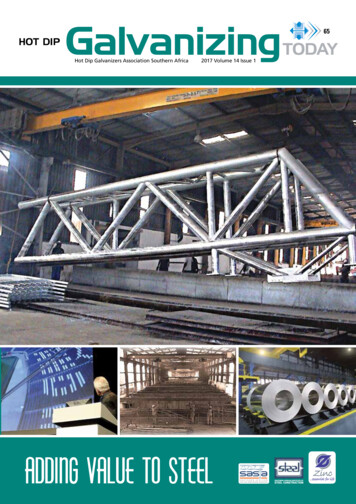
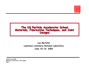
JAERI-Conf96-010A flow diagram is shown in Fig.l and specifications for the VCS are listed inTable 1. The VCS employs a dual system, each system consists of a CWP, two circulationpumps, a heat exchanger, surgetank, pipes and valves. The CWP occupies the upper, side,lower part, door and adjustable panel. Each circulation pump has complete capacity tocope with design specifications. The heat exchanger is a Shell-and-Tube type(water towater), and auxiliary coolant flow inside the tube.The capacity of the surgetank isdesigned on the basis of heat expansion of the coolant.3. Design of CWPThe VCS has to satisfy two stipulated requirements, removal of heat from theRPV and cooling the concrete wall of the RPV room. The basic structure of the CWP isdesigned in accordance with the calculations of heat distribution for the concrete wall ofthe reactor vessel room and the analysis of heat removal values in order to comply withtheir given specifications.3.1 Concrete cooling structureThe structure of the CWP is a panel structure with cooling water pipes weldedseparately with fin plates, to make the cool surface remove heat. The pipes of the bothsystems are arranged by turns to keep the heat removal equal. The relation between theseparation pitch of the cooling water pipes and concrete temperature is shown in Fig.2.Here it is found that the pitch to make the concrete temperature below 65 C is below170mm. For practical reasons we adopted a 120mm pitch for its advantages in coolingability.3.2 Structure to satisfy the limited heat removal valuesThe analysis of heat removal values was performed on the CWP considering thedistribution of emissivity on the surface of the cooling water pipes.(1) Design emissivityIt is known that emissivity has its distribution factors in surface conditions andtemperatures. Design emissivity values were decided based on several data' 6 . This datais shown in Fig.3.Design emissivity was decided at 0.85 as a maximum and 0.6 as a minimum and0.79 as a nominal value for surface conditions in operation. These designs agreed wellwith the aforesaid data.(2)Heat removal value326-
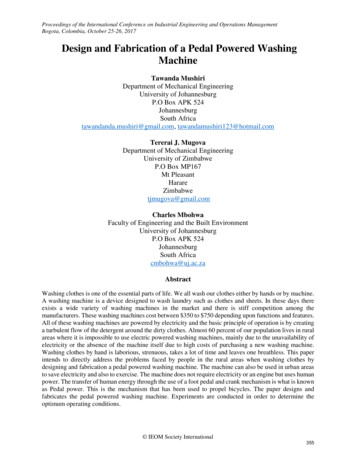
JAERI-Conf 96-010Regarding the CWP within 120mm as the pitch of the cooling water pipes, theanalysis of heat removal values was performed with the design emissivity. The results areshown in Fig.4. It was found here that a structure which could decrease the heat removalvalues was required.(3) Structure decreasing the heat removal valueTo decrease the heat removal value into the limits, additional structuresconsisting of heat reflector panels between the RPV and the CWP were added to thestructure, as they controlled heat removal value well and were easy to fabricate.Therelation between the number of reflectors and heat removal values is shown in Fig.4.It was found that heat removal value decreased in relation to the increase in thenumber of reflectors. When 4 reflectors were added, heat removal value was sustainedbelow the maximum limit at the maximum emissivity value. On the other hand, at theminimum emissivity value, it was 0.29MW and unable to maintain a level above minimumvalues.(4)Adjustable-panelMinimum heat removal values were satisfied by a modified CWP structure of 4reflectors. To decrease temperatures of the reflectors, additional cooling water pipes werearranged on the innermost reflectors.In this case the coolant flow was controlled byoperating valves outside the reactor vessel room. The relation between the number ofadded pipes in which the coolant flows and the heat removal value is shown in Fig.4. Itwas found that the heat removal value could be maintained at a minimum when the coolantwas flown in the pipes.4. Thermal radiation tests for CWPThermal radiation tests were carried out to verify both the design emissivity andthe performance of adjustable panels.4.1 Basic test for thermal radiationThe design emissivity was verified comparing measured heat removal values withcalculated values.The test equipment is composed of thermal reflectors arranged inconcentric circles, and electric heaters centered in thermal reflectors inside a water coolingjacket. Schematic representation of the test equipment is shown in Fig.5. The temperatureand flow rates of cooling water were measured to calculate the heat removal values. Thefollowing surface conditions for reflectors were prepared in this test:keeping in air afterthe shot blast (simulating before operation) and keeping at high temperature after the shot-327-
JAERI-Conf 96-010blast (simulating after operation). The metal as received was also tested for reference.The results of the thermal radiation test are shown in Fig.6, comparing measuredvalues with calculated value. As shown in Fig.6, the measured values are inside the bothlines, calculated by means of emissivity 0.6 and 0.85. As a result, it can be said that thedesign emissivity is reasonable. The measured value on the upper side of the calculationline at the temperature range of lossage, however is no problem because active cooling isrequested at the time of lossage.4.2 Heat removal testPerformance verification of adjusting panels was performed by comparingmeasured heat removal values of the test with calculated values. These tests were carriedout by means of the test equipment in Fig.7, and replacing the innermost reflector in Fig.5by a reflector with water cooling tubes.The results of the heat removal test are shown in Fig. 8, comparing measuredvalues with the calculation values. As shown in Fig. 8, the measured heat removal valuesincrease when running cooling water to the adjustable panel, and measured values areinside the both lines, calculated by means of emissivity 0.6 and 0.85. As a result, we canverify the performance of the adjustable panel and the calculated methods. The calculationwas carried out by means of the temperature distribution analysis, FEM. The calculationmodel is shown in Fig.9. Heat transfer roots by way of the water cooling tube and thethermal reflector are considered in this model.5. Analysis of heat removal values for the practical structure of the VCSThe analysis of heat removal values took into account design emissivity andproperty confirmation test results to evaluate practicability of the VCS structure.5.1 Analysis of heat removal valueThe analysis ofheat removal value was calculated with parameters in thenominal, maximum and minimum heat removal conditions. The maximum heat removalcondition was confirmed that the real heat removal value was lower than the calculatedone.For instance, the effects of natural convection were considered at the time ofmaximum condition. The minimum heat removal conditions confirmed that the real valuewas over the calculated values. For instance, the minimum emissivity without naturalconvection was adopted. These conditions are arranged in Table 2.These results of the analysis by the above three conditions are shown in Fig. 10.The results satisfied the limited maximum heat removal value as 0.49MW under nominalconditions 0.58MW under maximum conditions but the limited minimum heat removal-328-
JAERI-Conf 96-010value was 0.29MW nominal conditions.5.2 Heat removal Value adjustmentIn view of maintaining the heat removal capacity in the case of lossage, whenthe real heat removal value is below the limited minimum, adjustment was carried outassuming that the objective is over 0.45MW as shown below.If the heat removal value is 0.29MW,100 pipes of the adjustable panel's mustrun coolant in order to increase levels up to the designated objective. If the heat removalvalue is in region H, using the adjustable panel makes the heat removal value surpass thelimited maximum value. Therefore it was decided that the adjustable panel be a separateddual system and operation.As a result, if the heat removal value is in region I no adjustable panel is used, ifin region II one of adjustable panels is used and if in region HI both of them are used.Therefore, the actual heat removal value is able to cope with fluctuations in the region of0.45MW to 0.6MW despite the actual heat removal value distribution.6. Fabrication of the VCSSpecifications of the VCS were decided by calculations of heat distribution forthe concrete and the analysis of heat removal value considered above. A structural designof the VCS is given in Fig.ll. The CWP consists of the upper side, sides, lower side,door and adjusting panel. The upper panel has a round shape with penetrations for standpipes fitting into the upper barrier block covered on the RPV room. The side panel partsand side parts of the lower panel consist of 12 panels each fitting to dodecagon shape ofthe RPV room. Fig. 12 shows parts from 30 to 150 degrees of the overall picture of the 12panels. Specifications of the CWP are listed in Table 3.A sectional plan of the side panel is shown in Fig. 13. Water cooling pipes andfins are joined by welds and installed by bolts set on the concrete wall by nuts. Reflectorsand the adjustable panels are supported by bolts set on fins of the side panel.(Due toprevention of over-heating the concrete wall the number of bolts were minimized.) Eachof the side panel parts and side parts of the lower panel are fabricated in the worksseparately, and then transported to the HTTR site and installed in the RPV room.7. ConclusionThe CWP structure of thermal radiation cooling method was established for theVCS-panel of the HTTR.Heat removal value limits as well as temperature limits ofconcrete were satisfied through the thermal radiation cooling process which brought aboutthe following features.-329-
JAERl-Conf 96-010(1) A lower limit for heat removal values was established by additional reflectors to thecooling water pipes.(2) Heat removal values could be controlled by the addition of adjustable cooling panels atthe location of the innermost reflector. A lack of heat can be rectified by the flow ofwater in the pipes.(3)The compatibility of emissivity and analysis methods were confirmed through thermalradiation and heat removal tests, which agreed well with the calculated values.References1. JSME Data Book : Heat Transfer 4th Edition.2. William H. MacAdams: Heat transmission : Appendix, Asian Students' Edition,McGRAW-HILL BOOK COMPANY INC.3. James. R Welty ; Engineering Heat Transfer: Appendix, D John Wiley & Sons (1974)4. Siegel and Howel: Thermal Radiation Heat Transfer5. G Neuens: Influence of Surface Properties on the Total Emittance of Steel6. E.M.Sparrow, R. D. Cess: Radiation Heat Transfer: Chapter 2, McGRAW-HILLBOOK COMPANY INC. (1978)-330-
JAERI-Conf 96-010Air Conditioning Sys.Upper Panel—SidePanekCorrosion ProtectionLiquid supply Sys.AdjustablePanelLower PanelFig.lReactor Containment VesselFlow diagram of the VCS (Showing one of the two systems)Table 1- Design specifications of the VCSItemsNumber of systemsLimited heatremoval valueyimited temperatureof the concreteCoolantFlow rateMaximum operatingtemperatureMaximum operatingpressureClass of aseismicdesignSpecifications2 0. 3-0. 6H65 C Pure water86 metric ton per hour90 C0. 98HPaAsCirculation 2 per a systemVain components and pumpsnumber of eachHeat1 per a systemexchangercomponentsSurge tank1 per a systemUpper panelSide panelArrangement of theDoor panelStaler CoolingAdjustable PunolPanelLower panel-331-
JAERI-Conf 96-010Normal Operating CnndilonP: Tube Pilchil0.3Water Coolie TubeLi mileil Temperature J 0 . 1 0.7 S100Tube Pilch (nun)150200100CoolingWaterPanelFi g . 3Cooling Water Panel Thermal Reflector400500600Adjustable PanelThermalReflector\0.901300Cooling Water Panel Thermal ReflectorAdjustable Panel1.0s200'Emissivity data of carbon steel by public issue1.1oNominal 0.79Temperature IX)1.21 S;0Fig.2 Effect of tube pitch on the concrete tempernture1.3Maximum 0.85VMinimum 0.G0.650A ' ' :. : . - - 7 JCoolingWaterPanelConcreteEmissivity 0.850.80.7Upper Limit0.60.50.4Emissivity 0.6Lower Limit0.3jj - 2 9 ,01 23 - 1Number of reflectors of Side PanelJ050100Number of Using Tubes ofAdjustable PanelFig.4 Calculation results of heat removal value-332-
JAERl-Conf 96-010CoolingWaterOutletCFXTWater Cooling Jacket- J l , Cooling WaterInletThermalInsulation[Material]Simulated RPV: 2'ACr-Mo steelThermal Reflector : 2' Cr-Mo steeland Carbon SteelFig. 5 Equipment of basic test for thermal radiationCooling WaterOutletWater5Outlet I «ICooling WaterInlet ThermalInsulationJHeater-Simulated RPVWater Cooling Tubeof Adjustable PaneleeoooThermalReflectorWater Cooling Jacket t 1 9 OmmI"1a.Cooling WaterInletThermal"Insulation[Material]Simulated RPV: 2'AiCr-Mo steelAdjusted Panel: 2'/.iCr-Mo steelThermal Reflector : 2l/iCr-Mo steeland Carbon SteelFig.6 Equipment of heat removal test-333
JAERI-Conf 96-010[Surface Condition] : Keeping in Air after Shot Blast(Simulating before Operation) : Keeping at High Temperatureafter Shot Blast(Simulating after Operation)0 : As ReceivedEmissivity14/ 0.85I-aTemperature of RPV: 400*01.41.211.2Calculation Result Emissivity 0.85i 1.0Calculation Result/I/0.8/O.G/ Emissivity/y0.40.20.0t1.0 o0.8e0.C0.4x0.2) 2)L Normnl In Cnse of( Operation AccidentstEmissivity 0.60.00200-1000O00Temperature of Modeled RPV { C)2-1 GNumber of Using Tubes of Adjustable PanelFig.8 Results of heat removal value testFig.7 Results of thermal radiation testWater Cooling Tubeof Adjustable PnnolSimulated RPVHeaterWater Cooling Tubeof Adjusting PanelHeater:\Thermal ReflectorWater Cooling Jacket'Water Cooling JacketSimulatedRPVrThermal Reflector:Radiation(Test Model Structure)Fig.9(Calculation Model)Calculation model for heat removal test-334-"
JAERI-Conf96-010Table 2 Calculation conditions on heat removal valueof.the practical CoolinR Water Pancl(CTP)ItemsMaximum value Nominal value Minimum valueEmissivity0. 7 90. 8 50. 6Radiation0.9 60. 9configuration factors1. 0(between the RPVPaneland the CS'P)condition Surface area of the All surface All surface All surfaceCWParea without area without area withoutpenetrations penetrations penetrationsfor pipingfor pipingfor pipingand the standpipes surface3 5 CTemperature of the CVP1 7 C6 0"CNeat transfer throughconsidering consideringnotRoomtheCTP's supportconsideringcondition Heat transfer throughconsidering consideringnotthe RPVs stabilizerconsideringNatural convectionnotconsidering consideringconsideringPower level of2 9.2 5MW0. 7 5 M W3 0MWthe core Heat transfer of 1 0. 0W/VK 1 6. 7W/m-K 1 3 . 5ff/m KInnerthe corecondition Emissivityof the RPV Graphite block of1. 00. 81. 0the coreInner surface of1. 01. 00. 6the RPVUpper Limit0.60.58Natural TConvectiona,I0.58-,0.570.5Radiation Heat Conduction\ 0.31Using 2 PanelsUsing 1 Panel.Lower —\ 0.29Using No PipeLimit: Nominal ConditionD : Heat Removal Valueafter Adjusting012Flowing Number of Water Cooling Tube of Adjustable PanelFig. 10 Results of calculation of heat removal value-335-
JAERI-Conf 96-010Upper PanelLower panelFig. 11 Structure view of water cooling panel of the VCS-336-
JAERI-Conf96-010Table 3 Design data of the Cooling ffatcr PanelTube materialUpper panel Tube 0. D., mmTube thickness, mmNo. of lubesTube materialTube 0. D., mmTube thickness, mmSide panel No. of tubesThermal reflectorplates' materialand No. of platesTube materialAdjustable Tube 0. D., mmpanelTube thickness, mmNo. of tubesTube materialTube 0. D., mmTube thickness, mmLower panel No. of tubesThermal reflectorplates' materialand No. of platesTube materialDoor panel Tube 0. D., mmTube thickness, mmNo. of tubesSTB41015.93.248 per a systemSTB41025.4Side Panel3.5108 per a systemone plate made ofSUS304 and 3 platesmade of SPIICSTBA2425.43.548 per a systemSTH41025.43.5120 per a systemone plate made ofSUS304 and 3 platesmade of SPIICSTB41025.43.56 per a systemSTB410:Carbon steel boiler and heat exchanger tubesSUS304:Cold rolled stainless platesSPIIC :llot-rolled mild steel platesSTBA24:Alloy steel boiler and heat exchanger tubesSide Part of Lower PanelFig.12 Developed view of theside panel and thelower panel(from 30 to 150 )Embedded PlateConcrete/.,-o .o\»Finffater Cooling TubesFig. 13 Cross section of the side panel-337-
The reactor vessel cooling system (VCS) is an engineered safety device that is used as a decay and a residual heat removal system when forced circulation in both the primary and the auxiliary cooling systems canjiot be performed. The VCS consists of a Cooling Water Panel (CWP) and a water circulation system supplying a coolant.