Transcription
IOP PUBLISHINGJOURNAL OF MICROMECHANICS AND J. Micromech. Microeng. 21 (2011) 115014 (11pp)Rapid nano impact printing of silkbiopolymer thin filmsRobert D White1 , Caprice Gray, Ethan Mandelup, Jason J Amsden,David L Kaplan and Fiorenzo G OmenettoTufts University, Medford, MA 02155, USAE-mail: r.white@tufts.eduReceived 6 July 2011, in final form 22 August 2011Published 12 October 2011Online at stacks.iop.org/JMM/21/115014AbstractIn this paper, nano impact printing of silk biopolymer films is described. An indenter is rapidlyaccelerated and transfers the nanopattern from a silicon master into the silk film during animpact event that occurs in less than 1 ms. Contact stresses of greater than 100 MPa can beachieved during the short impact period with low power and inexpensive hardware. Ringshaped features with a diameter of 2 μm and a ring width of 100–200 nm were successfullytransferred into untreated silk films using this method at room temperature. Mechanicalmodeling was carried out to determine the contact stress distribution, and demonstrates thatimprinting can occur for contact stresses of less than 2 MPa. Thermal characterization at theimpact location shows that raising the temperature to 70 C has only a limited effect on patterntransfer. Contact stresses of greater than approximately 100 MPa result in excessivedeformation of the film and poor pattern transfer.(Some figures in this article are in colour only in the electronic version)emphasis on optical systems. Micromolding is a relativelyslow method of pattern transfer, requiring hours to complete.Nanoimprinting is a faster alternative to micromolding forprocessing polymers at the nanoscale. In nanoimprinting,nanopatterns are generated by pressing a polymer filminto a rigid stamp [12, 13]. The technique allows rapidreproduction of structures with 10 nm precision, and is acandidate to replace optical lithography in semiconductorprocessing. The technique has been most heavily studiedfor polymethylmethacrylate (PMMA) films [14]. Extendingthe technique to biopolymers is of interest, particularly forbiomedical applications. For example, recent work hasdemonstrated the ability to nanoimprint 100 nm featuresinto the biopolymer chitosan [15]. The first results fornanoimprinting into a silk biopolymer were reported in 2010[10, 11]. In both papers, the authors were able to demonstratethe transfer of patterns with dimensions of the order of100 nm into silk films at temperatures of 80–100 C and contactpressures of less than 0.35 MPa (50 psi) for times of the orderof 5 s.In this work, we explore the possibility of increasing thepattern transfer rate using very rapid ( 20 ms) nano impactprinting. In nano impact printing, the pattern is transferredIntroductionSilk biopolymers offer many attractive features for microand nano-scale devices. These materials are biocompatible,exhibit high mechanical toughness and excellent opticalclarity, and can be formed into a variety of structures includingthin films, fibers, fiber mats, gels, and foams [1–5]. Inaddition, the constructs have the ability to immobilize avariety of biochemical agents including enzymes and proteins,and maintain their activity over the course of years [6–8].As an added benefit, silk processing is relatively benign,occurring in an aqueous environment at neutral pH and ambienttemperatures.The transfer of nanoscale patterns into silk films is ofinterest for a variety of biophotonic devices that include opticalsensors, optical waveguides, tissue engineering scaffolds,and neural electrode arrays (e.g. [1–11]). Pattern transferof nanoscale features into silk films has been demonstratedrecently using both micromolding and nanoimprintingmethods. For example, in [9], the authors demonstrate theability to cast nanoscale patterns with 30 nm resolution insilk using soft lithographic micromolding techniques, with an1Author to whom any correspondence should be addressed.0960-1317/11/115014 11 33.001 2011 IOP Publishing LtdPrinted in the UK & the USA
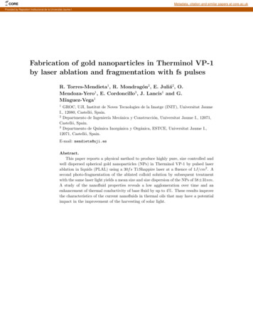
J. Micromech. Microeng. 21 (2011) 115014R D White et alprimarily by the high forces evolved during the impact ofan indenter into the film. The impact event itself occurs ontime scales of less than a millisecond. The entire processof impact printing including accelerating the indenter to theimpact velocity and bringing the indenter back up into theprint head occurs in less than 100 ms. Very high contactstresses ( 100 MPa) can be achieved during the short impactperiod. To the best of our knowledge this paper is the firstdemonstration of nano impact printing of any kind. Ringshaped features with a diameter of 2 μm and a ring width ofthe order of 100–200 nm were successfully transferred intountreated silk films using this method at room temperature,with contact stresses of less than 2 to 100 MPa. Contactstresses of greater than approximately 100 MPa result inexcessive deformation of the film and poor pattern transfer.A novel imprinting apparatus and method of manufacturingsilicon nano features for the impact stamp are also described.The large contact stresses that can be achieved in nano impactprinting may be an advantage in some applications, but maybe a disadvantage in other applications. The magnitude of theimpact stresses can be controlled through the design of theimprinting apparatus. This paper describes the contact andimpact mechanics in detail to assist in the design process.Figure 1. Schematic of the rapid imprinting setup.a hemispherical epoxy bump which provides the imprintingsurface (Devcon S-31/31345, ITW Performance Polymers,Riviera Beach, FL). The hemispherical bump is important togive a smooth impact surface, and also allows a range ofstresses to be evaluated during a single impact, as explainedbelow in the discussion of contact mechanics. The air cylindersare individually controlled via solenoid valves driven by aregulated air compressor. The impact velocity of the cylindersis controlled by changing the regulated air pressure, using aControlAir Inc Type 500X E/P transducer driven from thecomputer by an analog control voltage. For rapid nano impactprinting, the pressure is first set to the desired value, and thesolenoid valve is opened, allowing the most rapid possible risein pressure.Computer control and measurement, includingtemperature measurement via the thermocouple, controlof the micropositioning stages, and timed control of the aircylinder imprinters are accomplished using the NI USB-6008multifunction DAQ and Labview control software (NationalInstruments, Austin, TX) with appropriate power amplifiers.This custom setup allows very short imprint times throughcomputer control of the low-inertia indenters with goodknowledge of temperature and pressure.The silicon stamp used as the master surface to imprintthe film was manufactured using surface micromachiningtechniques. The starting substrates were 1 0 0 oriented,p-type (1–10 cm) silicon wafers. Shipley S1813 photoresistwas spun onto an 800 nm thickness and patterned via anoptimized UV contact lithography process. The mask patternused consisted of 2 μm squares arrayed on a 4 μm centerto-center pitch. After lithography, the corners of the squareswere rounded off by diffraction to form approximately 2 μmdiameter circles on a 4 μm pitch. The wafer was etched inan SF6 plasma using a parallel plate RIE etcher at 80 mT and150 W, for a silicon etch rate of 240–415 nm min 1 (the etchrate varied with radial position; it is faster near the edge),and a photoresist etch rate of approximately 250 nm min 1 .The samples were etched for 5 min. This intentional overetchcompletely removed the resist as well as etching down intothe silicon. Any remaining resist residue was then removedusing a high power O2 plasma, and the wafers were subdicedto produce the final nanoimprinting stamp.The SF6 overetch allowed the production of features belowthe diffraction limit of the NUV aligner. The resist is somewhat(hundreds of nanometers) thicker around the edge of the 2 μmcircles than the center. Thus, by overetching the sample,Material processingSilk fibroin solutions were prepared from Bombyx moricocoons through a process that has been described in detailelsewhere [16]. The process removes the sericin bindingprotein from the silk cocoon, dissolves the fibroin in LiBr,and then replaces the LiBr with deionized water through adialysis process, resulting in a solution of silk fibroin in water.Silk fibroin thin films were then prepared by drying 9% wt/volsilk fibroin solution in a petri dish for 24 h at room temperatureand ambient humidity (approximately 22 C, 50% RH). Carewas taken to level the dish with respect to gravity to ensurethickness homogeneity of the drying film. Seven milliliters ofsilk solution was used in each 100 mm diameter dish, resultingin optically clear films of 101 9 μm thickness, as measuredwith a micrometer.Once dried, the films are easily detached from the dish,cut to size, and mounted onto a rectangular acrylic frameusing doubleside tape (Catalog #137, 3 M, St Paul, MN).The frame is mounted into the custom rapid imprinting setupshown in figure 1. The impact printing setup is comprisedof a Cimarec hotplate, on which is mounted an aluminumbaseplate, secured tightly to the hotplate with mounting screwsand thermally connected with thermal grease. A siliconstamp is held in the center of the baseplate by a vacuumsystem. A type K thermocouple is mounted in a holewhich extends to the center of the baseplate, just below thesilicon stamp. An 80/20 aluminum frame holds a computercontrolled MTS50 XY micropositioning stage with 50 mmtravel (Thorlabs, Newton, NJ). The stage mounts to the frameholding the silk film, and can position the film relative tothe indenters and silicon stamp. The indenters are miniaturesingle acting air cylinders with a return spring. The fiveindenters each have 1.6 mm diameter shafts, terminated with2
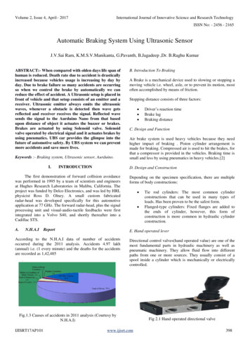
J. Micromech. Microeng. 21 (2011) 115014R D White et alFigure 2. The silicon stamp produced by overetching of the silicon surface in an SF6 plasma. (Left) SEM image showing the array of craters,and (inset) AFM image showing an individual nanocrater. (Right) cross-section from the AFM image through the center of the nanocrater.the nanopattern from the stamp to the silk film depends onthe radial distribution of the contact stress at the silk/siliconinterface. This problem has some similarities to the Hertziancontact problem between an elastic hemispherical indenter andan elastic half space [17–19]. In the classic Hertzian solution,the contact stress is3P 2σ (r) a r 2,(1)2π a 3where P is the total applied load, r is the radial coordinate, anda is the radius of the contact region, 1/33R E1 1 υ22 E2 1 υ12P,(2)a 4E1 E2Figure 3. Schematic of the contact mechanics problem.the combination of undercut and resist thickness variationallows the production of circular ‘crater’-like structures witha 2 μm diameter and a sharp 600 nm high ‘rim’. The rimstarts at approximately 500 nm in width and tapers to a sharpedge less than 100 nm in width. The precise shape of thesestructures varies over the wafer, due to radial nonuniformityin the etch rates. However, in a given millimeter sizedregion, the structures are uniform. Figure 2 shows scanningelectron microscope (SEM) and atomic force microscope(AFM) images of the silicon stamp structure in the regionin which the nanoindentation experiments were performed.Of the order of 50 impact experiments were conducted at thesame location in the silicon stamp. No degradation of thesilicon stamp was observed. The AFM and SEM images infigure 2 were taken after the impact experiments had beenconducted.where R is the radius of the indenter, and E1 , ν 1 , E2 , and ν 2 arethe elastic moduli and Poisson ratios for the indenter and thesubstrate. The Hertzian solution was compared to the finiteelement solution for low contact loads on the top surface, andmatched precisely, validating the finite element analysis (FEA)result at low loads.However, four major features distinguish the situationdescribed in this paper from the Hertzian contact problem.First, and most significantly, the indenter is traveling withsubstantial velocity prior to impact, and the forces requiredto decelerate the inertia of the moving indenter substantiallyexceed the static contact stresses. Second, the stresses arelarge enough to exceed the yield stress limit of the silk film,and possibly that of the epoxy indenter. Third, the stress ofinterest is at the bottom of the silk film, and not at the surfacebeing indented. Finally, the three layer structure with the stiffsubstrate (the silicon stamp) has an influence on the mechanics.Thus, in order to determine the expected contact stressdistribution between the silk film and the silicon stamp, afinite element model was constructed. The FEA model isa 2D axisymmetric static continuum mechanics model withelastic/perfectly plastic material models. Abaqus CAX4Hfour-node bilinear axisymmetric quadrilateral elements wereused with a constant pressure hybrid formulation. R 0.8 mmQuasistatic contact mechanicsFigure 3 shows a schematic of the contact mechanics occurringbetween the hemispherical indenter and the silk film. Thesilicon stamp is on the bottom side of the silk film. Forceapplied to the top of the indenter by air pressure causes theindenter to press the silk into the silicon stamp. Transfer of3
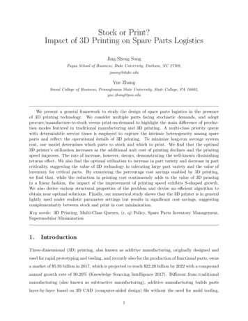
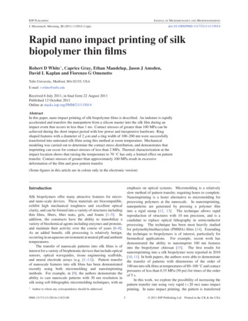
J. Micromech. Microeng. 21 (2011) 115014R D White et alis the radius of the indenter, h1 100 μm is the thickness of thesilk film, and h2 100 μm is the portion of the silicon stampthat is included in the analysis. This does not represent the fullthickness of the silicon, which extends to more than 500 μm,but is of sufficient size to capture the deformed region of thesilicon near the surface. An axisymmetric boundary conditionis applied along the symmetry axis at r 0. The base of thesilicon at z 0 has a fixed displacement boundary conditionin both the z- and r-directions. A displacement boundarycondition is applied to the top side of the epoxy indenter,moving the top surface uniformly downwards in a quasistaticfashion to a maximum displacement of 100 μm. The totalapplied load, P, is computed in post-processing by integratingthe normal stress over the boundary at each step.A surface-to-surface interaction is used to model thesurface contact between the silk and the epoxy. The epoxyindenter is the master surface and the silk film is the slavesurface. The mesh is a free quadrilateral mesh generated withan advancing front algorithm. The element size is biased witha 30:1 ratio toward the point of contact. Thirty elements areused in the z-direction in each of the three parts. 100 elementsare used in the r-direction in the silicon and silk parts.The elastic modulus and Poisson ratio of the silicon aretaken to be E3 190 GPa and ν 3 0.23 [20, 21]. E1 2.07 GPa, ν 1 0.4, and (E1 )y 78 MPa are the elasticmodulus, Poisson’s ratio, and yield stress of the epoxy indenter.The compressive elastic modulus and yield stress were takenfrom the manufacturer’s datasheets. The Poisson ratio is takenas the average value based on three different epoxies measuredby Fermilab [22]. Although these epoxies differ somewhatfrom the epoxy used here, the measured Poisson ratios onlyvary over the small range of 0.36 to 0.43. In the Hertziansolution, such a variation would result in at most a 5% changein contact stress, in the worst case where the deformation wasentirely limited to the epoxy.E2 4.1 GPa, ν 2 0.3, and (E2 )y 50 MPa arethe elastic modulus, Poisson’s ratio and yield stress of thesilk thin film. The Poisson ratio for silk thin films is anestimate following the argument of Pérez-Rigueiro et al [23].The elastic modulus of the silk thin film was measured at20 C using tensile testing in an Instron Model 3366 uniaxialtensile tester with video extensometer and BiopulsTM (Instron,Norwood, MA) pneumatic grippers. A 106 μm thick silk thinfilm was cut into a ‘dogbone’ shape with a 10 mm long, 3.2 mmwide test section expanding to wider ends for clamping. Thesample was loaded at a strain rate of 0.1% strain per second tofailure while monitoring the applied load. The resulting stresstrain curve is given in figure 4 below. The elastic modulusof the film is 4.1 GPa and the ultimate tensile strength is50 MPa. Note that the tensile measurements of silk filmproperties presented here are 30% higher, but nearly withinthe error bounds, when compared with tensile measurementsof untreated (air dried) silk fibroin thin films given elsewhere.For instance, Jiang et al and Noishi et al measure elasticmoduli of 3 1 GPa and ultimate tensile strengths of30 10 MPa [24, 25]. The ultimate tensile strength may notbe identical to the compressive yield strength. However, thisis the best estimate of the compressive yield strength available,Figure 4. Silk film tensile testing results at 20 C. Material is linearelastic with an elastic modulus of 4.1 GPa and an ultimate tensilestrength of 50 MPa.as no other consistent data have been generated to the author’sknowledge for compressive yield strength of silk thin filmsof this type. Attempts made as part of this study to measurecompressive yield strength by nanoindentation did not produceconsistent results.A result for the normal stress distribution in thez-direction, σ zz , is shown in figure 5 below. The figure showsthe region near the contact point. This particular result is fora total applied load of 0.3 N. At this load, plastic yielding hasalready occurred in a sub-surface region in the silk film.From the finite element computations, we can extractboth the total load verses displacement of the indenter, andthe contact stress distribution at the bottom of the silkfilm where it interacts with the silicon stamp, as shown infigure 6. The predicted stress distribution at three differentloads is also shown in figure 6. These three loads correspond tothe maximum loads expected during impact for three differentsupply pressures (20, 25, and 40 psi), as computed below inthe discussion of impact mechanics.Force and velocity measurementsForce measurements were made prior to the imprintingexperiments for each of the piston imprinters to determine theimprinting force. A Sensotec model 31 miniature load cell wasused for this purpose (Honeywell Sensotec-Lebow, Columbus,OH). The sensor was first calibrated statically against standardweights to remove offset and sensitivity drift. The load cellwas thread mounted into a test plate and placed at the samedistance from the stage as the baseplate, with a piece of siliconand silk on top of the sensor to mimic the imprinting setup.Separate measurements were then carried out for each pistonimprinter at five different supply pressures (20, 25, 30, 35, and40 psi), and for various pressure rise times and dwell times(as shown in table 2). Repeatability was checked five times,and variation from piston to piston or run to run was noted.In the medium force case (1.0 N average force) run-to-run4
J. Micromech. Microeng. 21 (2011) 115014R D White et alFigure 5. Abaqus result showing the stress field in the indenter and the silk films for a load of 0.3 N. (Left) normal stress in the z-direction.(Right) von Mises stress. Stresses are indicated in units of Pa.Contact Normal Stress (MPa)20031 N17 N6N150100500050100150200250Radial Position (μ m)300350400Figure 6. Finite element results showing (left) total force versus deflection of the top of the indenter (right) normal (z-direction) contactstress at the interface between the silk film and silicon stamp, for three different applied loads, as a function of radial position.and piston-to-piston repeatability (N 5) both have standarddeviations of 0.06 N. Five force cases were run, with averageforces of 0.26 0.02, 0.63 0.01, 1.00 0.02, 1.36 0.02and 1.70 0.02 N. The reported uncertainties are the standarddeviation of the static force measurements for different risetimes and dwell times (N 5–8).The total imprint dwell time (the time that the piston isstatically in contact with the film following the impact) wasalso determined from the load cell data. Variation in imprintdwell time from run to run was less than 20 ms. The measuredrise time and fall time were also approximately 20 ms. Fromthe data, it is not directly known whether this is the actualforce rise time or the rise time of the sensor; however, impactcomputations below suggest that there is a much larger impactforce which occurs in times of less than 0.1 ms. This is notseen in the data, so it seems likely that the sensor rise timeis of the order of 20 ms and it is incapable of capturing thehigh force impact event. Therefore, we can conclude from themeasurements that the actual rise time during the impact isless than 20 ms, but no more precise timing data are available.The uncertainty in imprint time is taken to be the measuredrise time: 20 ms.For the impact imprinting case, the momentum of theimprinter just prior to contact with the film is of primaryimportance. This quantity depends on the moving mass ofthe imprinter and its velocity just prior to impact. One of thepiston imprinters was cut apart, and the moving pin and pistonassembly was massed on a precision balance yielding a value of610 1 mg. The velocity of the moving piston was measuredusing a non-contact laser displacement sensor, Keyence modelLB-70W (Keyence Corporation, Osaka, Japan). The sensorhas a 0.7 ms sample time, and is capable of measuring thedistance to a reflecting object with a manufacturer specifiedprecision of 0.18 mm. The total travel distance of the5
R D White et al1.81.81.61.6Measured Impact Velocity (m/s)Measured Static Force (N)J. Micromech. Microeng. 21 (2011) 3035Piston Pressure (psi)400154520253035Piston Pressure (psi)4045Figure 7. (Left) load cell measurements of static force for different supply pressures. (Right) laser measurements of the velocity of theindenter just prior to impact for different supply pressures.piston is 11 mm. The piston was mounted sideways andthe Keyence sensor was used to measure the position of thehead during extension at the five different supply pressures(20, 25, 30, 35, and 40 psi) for the rapid rise time case( 20 ms force rise time). The analog voltage correspondingto displacement was captured with the computer DAQ systemwith a 10 kS s 1 sampling rate, and the resulting displacementresults differentiated in post-processing to compute velocity.A four-point moving average was applied after differentiationto reduce numerically amplified noise. The velocity justbefore the piston reached the end of travel was recorded.Velocity was measured to be relatively constant over thesecond half of the travel distance of the piston, so the resultsshould not be sensitive to the exact distance to the impactlocation. Variations in velocity over the course of pistontravel and sensor noise contribute to approximately 0.2 m s 1of uncertainty in the measurement. The impact velocitiesmeasured for the five supply pressures are 0.34 0.13,0.90 0.28, 1.18 0.19, 1.25 0.24, and1.53 0.21 m s 1 . More variation in velocity is observedat low pressure levels. The results are consistent with the totaltravel distance for the piston, and show an increasing trendof velocity with pressure, lending a level of confidence to theresults. The results for both static force and impact velocityare plotted against supply pressure in figure 7.Table 1. Results of impact mechanics calculation.Maximum indenter force occurs e m 6.1 10 4 kg is the moving mass of the piston,and F is the force applied by the substrate on the piston.Since the silk film deforms as the piston indents into it, Fis a function of displacement of the top of the indenter, x.Since the polymer may exhibit viscoelastic properties, forcemay also be a function of velocity, ẋ. Rather than attemptingto incorporate the temperature and hydration dependentviscoelastic properties of the silk films, as an approximation,we take the material to be elastic/perfectly plastic. We canthen extract the force–displacement characteristics from theFEA shown in figure 6. A good fit to the FEA result, shownin figure 6, isF (x) ( 4.27 · 10 5 )x 3 (7.94 · 10 3 )x 2 0.236x, (4)where F(x) is the force in newtons and x is the displacementin micrometers. If we numerically solve (3) with the initialvelocity set to the measured impact velocity, we can arrive atan estimate of the total distance traveled by the indenter topas it decelerates, and hence the maximum restoring force, thatoccurs during the impact event. This is the distance traveled, x,time, t, and force, F(x), at which the indenter velocity, ẋ, firstgoes to zero. The results of this computation are summarizedin table 1.It is emphasized that this calculation is approximate,since the analysis does not include any viscoelastic energydissipation mechanisms which may be present in the film,and also neglects the inertia of the film material andImpact mechanicsIn nano impact printing, the film is indented primarily by themomentum transfer during the impact, rather than the staticload. This can be seen by analyzing the measured velocityresults in light of the expected load deflection characteristicsof the film. In order for the indenter to decelerate from theimpact velocity to rest, the full momentum of the indenter mustbe transferred to the film. In order to conserve momentum,however, we require thatmẍ F (x, ẋ),Initial velocity(m s 1 )(3)6
J. Micromech. Microeng. 21 (2011) 115014R D White et alTable 2. Nano impact printing parameters.ParameterValuesUncertaintySurface temperature ( C)Dwell time (s)Static imprint force (N)Impact velocity (m s 1 )19, 38, 700.1, 0.25, 0.5, 1, 20.26, 0.63, 1.00, 1.36, 1.700.34, 0.90, 1.18, 1.25, 1.53 2 C 20 ms 0.06 N 0.28 m s 1any resulting structural vibrations that may be generated.Such calculations cannot be carried out without significantadditional characterization of the viscoelastic properties of thesilk film.The major result of this computation is that the momentumtransfer results in much higher peak force (5.2–30 N predicted)than the static force (0.26–1.7 N measured). Thus, momentumtransfer from the impact is expected to be the dominantmechanism for nano impact printing. This suggests that nochange in imprint pattern should be observed for differentdwell times. This is indeed what is observed experimentally.In addition, the impact calculation predicts that the impactevent occurs in less than 0.1 ms. This is faster than the loadcell can respond, which is of the order of 20 ms. Hence, asdiscussed previously, the load cell is not expected to registerthe large impact forces; it can only be used to measure thestatic load present during the static dwell.Figure 8. Light microscope picture (transmitted light, darkfieldillumination) showing the diameters of the outer and inner imprintedregions for a 1.2 m s 1 , 38 C impact print. This is a typical result.and the imprinting stamp. Nano impact experiments wereconducted with the silk film initially at these two temperaturesin addition to room temperature tests.Local transient temperatures near the impact may beelevated above the static temperature maintained by thehotplate. Since the collision is inelastic, much of the kineticenergy is transformed into thermal energy. This will causea local rise in the temperature of the film near the impactsite. The total kinetic energy of the indenter is knownprior to impact. In order to gain a sense for the possibletemperature change, consider the highest velocity case, wherethe kinetic energy just prior to impact is 0.7 mJ. No diffusioncalculations were conducted, but if all of this energy were usedto raise the temperature of a 100 μm cube near the impactsite, the temperature would rise approximately 440 C, takingthe silk film volumetric heat capacity to be approximately1.6 J K 1 cm 3 [26]. No independent measurements of localtemperature change or detailed thermal analyses were carriedout in this study, nor were any local changes in the silk filmproperties measured. However, the potential for substantiallocal temperature rise in the region of the impact is noteworthyand warrants further study, particularly if the silk film is to bedoped with thermally sensitive agents.Temperature measurementTemperature measurements during processing were madeusing a K-type thermocouple embedded in the center of thealuminum baseplate below the silicon stamp (see figure 1).While it is convenient to measure the temperature at the platecenter during processing, the relevant quantity is the surfacetemperature of the silicon stamp. In order to relate the two, aninfrared (IR) emission measurement was made of the siliconstamp surface. A piece of silicon identical in dimensionsto the stamp, but without surface nanopatterns, was cut andpainted with a thin black film using DE1634 Dupli-Color lowgloss black engine enamel (Dupli-Color Products, Cleveland,OH). This paint has been carefully characterized and has ahemispherical emissivity of 0.83 across a wavelength rangeof 1.5 to 50 μm at 32 C. There is less than 1% change inemissivity from 32 to 102 C, translating to less than 1% errorin measured temperature across that range.A Fluke 62 Mini IR Thermometer was used to measurethe temperature of the painted silicon (Fluke Corp., Everett,WA). The latter device assumes an emissivity of 0.95. Aftercorrecting for the actual emissivity of the material (whichcreates a 3.4% increase in actual temperature over measuredtemperature), the surface temperature of the silicon stamp ismeasured to be 38 C for a thermocouple reading (inside thebaseplate) of 45 C, and 70 C for a thermocouple reading of75 C. Based on manufacturer error bounds, the IRthermometry measurements are expected to be accurate towithin 2 C. Note that these temperatures a
silicon stamp is on the bottom side of the silk film. Force applied to the top of the indenter by air pressure causes the indenter to press the silk into the silicon stamp. Transfer of the nanopattern from the stamp to the silk film depends on the radial distribution of the conta