Transcription
Water conservation incoal-fired power plantsAnne M CarpenterCCC/275February 2017 IEA Clean Coal Centre
Water conservation in coal-firedpower plantsAuthor:Anne M CarpenterIEACCC Ref:CCC/275ISBN:978–92–9029–598-3Copyright: IEA Clean Coal CentrePublished Date:February 2017IEA Clean Coal CentreApsley HouseThird Floor176 Upper Richmond RoadLondon SW15 2SHUnited KingdomTelephone: 44(0)20 3905 3870www.iea-coal.orgIEA Clean Coal Centre – Water conservation in coal-fired power plants2
PrefaceThis report has been produced by IEA Clean Coal Centre and is based on a survey and analysis of publishedliterature, and on information gathered in discussions with interested organisations and individuals. Theirassistance is gratefully acknowledged. It should be understood that the views expressed in this report are ourown, and are not necessarily shared by those who supplied the information, nor by our member countries.IEA Clean Coal Centre is an organisation set up under the auspices of the International Energy Agency (IEA) whichwas itself founded in 1974 by member countries of the Organisation for Economic Co-operation andDevelopment (OECD). The purpose of the IEA is to explore means by which countries interested in minimisingtheir dependence on imported oil can co-operate. In the field of Research, Development and Demonstrationover fifty individual projects have been established in partnership between member countries of the IEA.IEA Clean Coal Centre began in 1975 and has contracting parties and sponsors from: Australia, China, theEuropean Commission, Germany, India, Italy, Japan, Poland, Russia, South Africa, Thailand, the UAE, the UK andthe USA. The Service provides information and assessments on all aspects of coal from supply and transport,through markets and end-use technologies, to environmental issues and waste utilisation.Neither IEA Clean Coal Centre nor any of its employees nor any supporting country or organisation, nor anyemployee or contractor of IEA Clean Coal Centre, makes any warranty, expressed or implied, or assumes anylegal liability or responsibility for the accuracy, completeness or usefulness of any information, apparatus,product or process disclosed, or represents that its use would not infringe privately-owned rights.IEA Clean Coal Centre – Water conservation in coal-fired power plants3
AbstractThe vulnerability of the power generation industry to constraints in water availability is widespread andgrowing, and this is increasing the pressure on power plant operators to conserve water. This reportdiscusses where water can be conserved or recovered within pulverised coal-fired power plants. It includesways of saving water in bottom ash handling, pollution control, and cooling systems. Cooling typicallyaccounts for the largest usage of water (where water is the coolant), and wet flue gas desulphurisation isthe second largest use at wet-cooled plants. Techniques for recovering water from the pulveriser andpre-dryer exhausts, and from the flue gas are also discussed. If sufficient water can be economicallyrecovered from the flue gas, then a dry-cooled power plant could become a supplier of both electricity andwater.IEA Clean Coal Centre – Water conservation in coal-fired power plants4
Acronyms and IEALNDDCTNETLNSFPCMPMSCRSDSTMCTSCUSDOEWESPWTA air-cooled condensercarbon capture and storagecirculating dry scrubberscycles of concentrationduct sorbent injectionElectric Power Research Institute (USA)electrostatic precipitatoreconomiser sorbent injectionEuropean Unionflue gas desulphurisationfurnace sorbent injectionGetting Water from LigniteInternational Energy Agencylitresnatural draught dry cooling towerNational Energy Technology Laboratory (USA)National Science Foundation (USA)phase change materialparticulate matterselective catalytic reductionspray dry scrubberstransport membrane condenserthermosyphon coolerUnited States Department of Energywet electrostatic precipitatorWirbelschicht-Trocknung mit interner Abwämenutzung (fluidised bed drying with internal wasteheat utilisation)Conversions1 m3 1000 litres1 t water 1 m3IEA Clean Coal Centre – Water conservation in coal-fired power plants5
ContentsPreface3Abstract4Acronyms and abbreviations5Contents6List of Figures7182IntroductionWater recovery from coal2.1 Water recovery from mill exhaust2.2 Pre-dryers2.3 Comments3Ash handling systemsWet ash systemsSemi-dry systemsDry ash systemsComments1717181920Pollution control systems4.1 Particulate control4.2 Desulphurisation systems2121223.13.23.33.444.2.14.2.24.2.35Wet scrubbersSemi-dry processesDry technologies2326274.3 CO2 capture4.4 Multi-pollutant systems4.5 Comments282929Water recovery from flue gas5.1 Condensation31315.1.15.1.2612131416Direct contact coolersIndirect contact coolers31325.2 Liquid desiccants5.3 Membranes5.4 Comments333537Cooling systems6.1 Open-loop cooling39396.1.1Steam condenser developments6.2 Closed-loop cooling6.2.16.2.26.2.3EvaporationDrift and plume abatementBlowdown6.3 Dry g the inlet airDeluge coolingConventional ACC developmentsAlternative dry cooling technologies6.4 Hybrid cooling6.4.1Hybrid cooling towers6.5 Comments40414246474850505252535455577Discussion and conclusions598References62IEA Clean Coal Centre – Water conservation in coal-fired power plants6
List of FiguresFigure 1 Schematic of a power plant showing where water is lost and added10Figure 2 Water balance on a subcritical 500 MW power plant10Figure 3 Flowsheet of the GWFL system13Figure 4 WTA lignite drying process as used in the prototype at Niederaussem15Figure 5 Dewatering bin system18Figure 6 A typical limestone wet scrubber system24Figure 7 Possible sorbent injection points27Figure 8 Total water use with CCS28Figure 9 Direct contact flue gas condensing system32Figure 10 Two-stage TMC integration in a coal-fired power plant37Figure 11 Water flow in a steam condenser40Figure 12 Water flow in an induced draught cooling tower41Figure 13 Schematic of proposed fill arrangement44Figure 14 Direct dry cooling with mechanical draught ACC48Figure 15 Indirect dry cooling49Figure 16 A dual coil closed-circuit cooling system56IEA Clean Coal Centre – Water conservation in coal-fired power plants7
Introduction1IntroductionWater and energy are basic necessities of human well-being and prosperity. They are mutually dependent,with energy production requiring large volumes of water and the water infrastructure requiring largeamounts of energy. For example, the water system in the USA consumes over 12% of national energyproduction (Hightower, 2014), whereas thermal power generation alone was responsible for 45% of waterwithdrawals in 2010 (although most of this water is returned to the source) (Maupin and others, 2014).This interdependency has been called the ‘water-energy nexus’, and is explored more fully in an earlierreport from the IEA Clean Coal Centre (Carpenter, 2015). The demand for energy and water is increasingas a consequence of population and economic growth, and higher living standards. Water demandworldwide has been projected to grow by 55% between 2000 and 2050, principally due to rising demandfrom manufacturing, thermal power generation, and domestic use (OECD, 2012). Global energy demandhas been projected by the International Energy Agency (IEA, 2012) to rise by 35% between 2010 and 2035,with the demand for electricity expanding by some 70%. This projection is in their New Policies Scenario,which takes into account existing and planned government policies.Withdrawal of water for power generation (which accounts for over 90% of energy-related waterwithdrawals) is projected by the IEA (in the New Policies Scenario) to rise by 3.7%, from 540 billion m3 in2010 to 560 billion m3 in 2035. However, water consumption, that is, the amount of water that iswithdrawn and not returned to the source, could increase by almost 40% (IEA, 2012). These two trendsare the result of a shift towards higher efficiency power plants with advanced cooling systems that reducewithdrawals. Cooling accounts for the largest usage of water at a wet-cooled coal-fired power plant (seeChapter 6). The more efficient wet-cooled supercritical and ultrasupercritical plants typically use 15-20%less water than subcritical ones.The vulnerability of the power generation industry to constraints in water availability is widespread andgrowing (Carpenter, 2015). Significant areas of almost every continent face a high level of water stress,including large areas in China, India, South Africa, and the USA – the four top thermal coal consumingcountries in the world. Regions where water is scarce face obvious risks, but even regions with ampleresources can experience constraints due to droughts, heat waves, seasonal variations and other factors.For example, a number of power plants in India had to shut down temporarily during 2016 due to a lack ofwater, including five units (totalling 1600 MW) at the Farakka coal-fired power plant in West Bengal, andfour units (2600 MW in total) at the Tiroda plant in Maharashtra (Power, 2016). The power generationindustry in the water-abundant north-east region of the USA is facing issues of water quality andtemperature. Power plants have had to close down at times to ensure they do not exceed the permittedwater discharge temperature.The number of plants affected is likely to increase in the future, with serious economic consequences.Furthermore, ground water supplies are diminishing with an estimated 20% of the world’s aquifers alreadyover-exploited (WWAP, 2015), and the quality of the water is deteriorating. Consequently, competition8IEA Clean Coal Centre – Water conservation in coal-fired power plants
Introductionbetween power plant operators and other water users is likely to escalate, and climate change could furtherexacerbate the situation. Regulatory restraints by governments may impose limits on, or increase the costof, fresh water usage by power plants. All of these factors are increasing the pressure on power plantoperators to reduce water consumption and/or to look for alternative or supplementary non-fresh watersources.This report continues a series relating to water and the power generation industry. The first one looked atwhere water stress is occurring in the world today, before it examined the availability and consumption ofwater within China, India, South Africa and the USA. It also discussed central government energy, climateand water policies and how they affect the coal-fired power generation sector in these four countries(Carpenter, 2015). The second report discussed alternative non-fresh water sources in the same fourcountries (Carpenter, 2016). The sources were municipal waste water, brackish and sea water, mine water,produced water from oil and gas wells, and water extracted from saline aquifers during CO2 storage. Anearlier report covered low water flue gas desulphurisation (FGD) technologies (Carpenter, 2012). Thisreport looks at how water can be conserved within a pulverised coal-fired power plant. A report publishedrecently by the Asia-Pacific Economic Cooperation (APEC) reviews technology developments, bestpractices and current policy measures related to coal power generation and clean coal technologies in APECcountries (DNV GL, 2016).Water is essential for power generation. Heat (from the combustion of coal) is used to convert water intohigh pressure, high temperature steam, which is expanded through a turbine to produce electricity. Thereare many different designs for pulverised coal-fired power plants. One design and its associatedwater-steam and flue gas paths are illustrated in Figure 1. Water exits the system in various ways. Thesecan be broadly classified as: unavoidable losses, such as through the evaporation of recirculated water in wet cooling towers, andminor steam leaks; losses to the formation of products, such as gypsum from the wet FGD scrubber; deliberate blowdown from various recirculating streams, including boiler feedwater, FGD streamsand cooling water. Blowdown is necessary to preserve water quality and remove impurities; and handling products, such as ash sluicing.The main places where water is lost and added (water make-up) are indicated in Figure 1.9IEA Clean Coal Centre – Water conservation in coal-fired power plants
IntroductionFigure 1 Schematic of a power plant showing where water is lost and addedFigure 2 shows the water balance for a 500 MW subcritical, bituminous coal-fired power plant; it gives anindication of the amount of water consumed. The plant layout is basically that shown in Figure 1. Theparticulate control device is a fabric filter (baghouse) and it uses a wet limestone forced oxidation FGDsystem (wet FGD scrubber).Figure 2 Water balance on a subcritical 500 MW power plant (Carney and Shuster, 2014)The report begins by describing techniques for recovering water from coal. Low rank coals are sometimesdried before combustion to improve power plant efficiency. The evaporated water can be recovered fromthe mill (pulveriser) exhaust or from pre-dryers. Ash existing the bottom of the boiler can be handled wetor dry, and this is the subject of Chapter 3. The next chapter examines ways of conserving water in pollutioncontrol systems, in particular, FGD. Wet FGD systems typically account for the second largest usage of water10IEA Clean Coal Centre – Water conservation in coal-fired power plants
Introductionat a wet-cooled power plant (see Figure 2). The flue gas exiting the boiler contains a large amount of watervapour. The 500 MW subcritical plant, whose water balance is shown above, discharges some 390 L/MWhfrom the flue gas stack. If lignite was fired, instead of bituminous coal, then even more water vapour wouldbe lost if the lignite is not dried prior to combustion. Technologies for recovering water vapour are coveredin Chapter 5. Finally, ways of conserving water in cooling systems are examined.Boiler feedwater is generally a mix of returned steam condensate and fresh make-up water. Make-up wateris required to compensate for leakages (very small) and sootblowing steam used to clean the boiler tubes.Blowdown is also necessary to preserve the high purity of the water and steam in the system. Make-upusage accounts for about 1–2% of steam flow, or about 30 L/MWh in a 500 MW subcritical power plant(see Figure 2). Although not insignificant, it is much less than for cooling or FGD water make-up. There aresmart systems available that can minimise the sootblowing steam consumption. Otherwise compressed airor acoustic sootblowers could be installed. Water recovered from coal or flue gas could be used for boilerfeedwater make-up to reduce fresh water consumption. Since much of the water loss cannot be avoided,boiler feedwater make-up is not covered any further in this report.Improving plant efficiency, for example, by utilising waste heat, reduces the amount of heat rejectionrequired per unit of power produced and therefore, decreases water demand; but this topic is outside thescope of the report, as is water treatment for the reuse of waste water generated within the power plant.11IEA Clean Coal Centre – Water conservation in coal-fired power plants
Water recovery from coal2Water recovery from coalLow rank coals are widely used for power generation in a number of countries, including Australia, China,Germany, Greece, India, Poland and the USA. Many of these plants are in water-stressed areas, and sorecovering the moisture from the coal could provide water for internal use. Lignites can have inherentmoisture contents as high as 70%. The coals can be dried before they are combusted. In conventional powerplants, the drying takes place within the mill. Here, the beater wheel mills not only break up the coal, butalso draw the hot furnace gas (1000 C) from the boiler to evaporate the moisture and convey the pulverisedlignite and water vapour to the burners. The use of such high grade heat for drying and passing all theevaporated moisture through the boiler results in lower power efficiencies and higher CO2 emissions thanfrom plants firing lower moisture coals at similar steam conditions. Pre-drying lignite before it enters themill (preferably using low-grade heat) offers the potential to recover the evaporated moisture from thedryer exhaust. Otherwise, the water vapour could be recovered from the mill exhaust. Both options wouldalso result in a lower flue gas volume and consequently, lower water consumption in wet cooling towers(see Section 6.2) and wet FGD systems, especially if the temperature of the flue gas has been reduced beforeit enters the FGD system (see Section 4.2.1). Moreover, the plant’s thermal efficiency could increase byabout 1 percentage point (lower heating value, LHV) when retrofitted to existing lignite-fired power plants;thermal efficiency could increase by 4–5 percentage points (LHV) in new dry lignite-fired power plants(and CO2 emissions decrease by over 10%), and a further 2–3 percentage points can be expected if 700 Cadvanced steam conditions are adopted (Dong, 2014; Henderson, 2013). Higher rank bituminous coalshave a lower moisture content and therefore, a lower amount of water would be recovered. This chapterwill focus on pre-drying low rank coals with water recovery.A number of technologies for removing water from low rank coals have been developed or are underdevelopment. These can be categorised into: evaporative processes, where the moisture is driven off as vapour; non-evaporative dewatering processes, where the moisture is removed as a liquid. These includethermal dewatering, mechanical thermal expression, and solvent extraction processes. However, thewater discharged from these processes often requires expensive treatment before it can be used.Some of the commercial or near-commercial pre-drying technologies that have been integrated intopulverised coal-fired power plants are described. These evaporative processes use hot air, flue gas or steamfrom the power plant as the drying medium. Coal drying systems that are operated separately from anon-site power plant will not be covered, although the recovered water could potentially be used by thepower plant. The chapter begins with developments in recovering water from the mill exhaust beforediscussing water conservation from pre-drying the coal before it enters the mill. Technologies for dryingwere primarily developed to improve the thermal efficiency of power generation rather than for waterrecovery. The evaporated water vapour is often emitted to the atmosphere but could be recovered for usewithin the power plant. More information on low rank coal drying technologies are available in the IEA12IEA Clean Coal Centre – Water conservation in coal-fired power plants
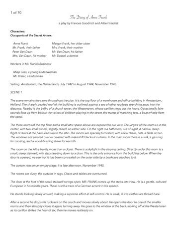
Water recovery from coalClean Coal Centre reports by Dong (2011, 2014) and Zhu (2012), and in more recent reviews byNikolopoulos and others (2015) and Rao and others (2015).2.1 Water recovery from mill exhaustA proposed plant modification from CastleLight Energy Corp. (see www.Castle-Light.com) uses a mixtureof flue gas from the economiser and the air heater to dry coal within the mill. The wet exhaust (sweep) gasand pulverised coal are separated in a small fabric filter (baghouse), one for each mill. The dried pulverisedcoal is then conveyed to the coal burners, and water is recovered from the exhaust gas using a heatexchanger. A 600 MW power plant firing Powder River Basin subbituminous coal ( 30% moisture) is driedto less than 10% moisture (by removing surface water in roughly one second), and about half of theevaporated water could be recovered for boiler feedwater make-up or other purposes (Moore, 2016).A new technology being developed in China is the Getting Water from Lignite (GWFL) system (see Figure 3).High temperature flue gas extracted from the upper part of the boiler and low temperature flue gas fromthe rear of the boiler are mixed and transported through a membrane-cooled high temperature pipeline toa drying tube. Here, they pre-dry the raw lignite ( 30% moisture), quickly turning the moisture into steam.The steam and coal then enter a fan (beater wheel) mill, where further drying of the coal occurs. The steamand pulverised coal are separated, and the steam is then condensed in a heat and water recovery device(an ultra-low temperature heat exchanger). The pulverised coal passes into a bunker before beingdelivered to the coal burners. Field tests of the system have been carried out on a 100 MW unit.Figure 3 Flowsheet of the GWFL system (Hu and Pei, 2015)Water is also saved in the FGD system as the cool exhaust gas exiting the water and heat recovery unitreduces evaporation losses. The condensate can be used for make-up purposes after treatment; the wateris weakly acidic and the main contaminates are suspended solids. Zero water make-up can be achieved onsupercritical or ultrasupercritical units employing dry (air) cooling systems (Hu and Pei, 2015).13IEA Clean Coal Centre – Water conservation in coal-fired power plants
Water recovery from coalCalculations by Ma and others (2013) for a 600 MW supercritical plant employing a version of the GWFLsystem suggest that some 84% (131 t/h) of the water vapour in the mill exhaust could be recovered with a39.5% moisture lignite. This is enough to meet the entire water consumption of an air-cooled plant with awet FGD system. The drying agent is a mixture of hot flue gas from the boiler and mill exhaust gas. Variousdrying agent options, namely hot air from the air heater outlet, mill exhaust from the pulverised coalcollector outlet or hot mill exhaust from the air heater outlet, each mixed with hot flue gas from the boiler,were later investigated by Ma and others (2015). The highest water recovery was achieved with a mixtureof hot flue gas from the boiler outlet and hot mill exhaust from the air heater outlet.Instead of the waste heat and water recovery device shown in Figure 3, Han and others (2017) investigatedusing a low pressure economiser for wet-cooled units, and a spray tower integrated with a heat pump forair-cooled units. Some 39% of the water vapour from the mill exhaust could be recovered with a lowpressure economiser on a 600 MW plant firing 39.5% moisture lignite. As a result, about 110 t/h(0.18 t/MWh) of water could be saved; this would at least be enough to supply the make-up waterrequirements of the wet FGD system. Some 189 t/h of water (0.31 t/MWh) could be saved with the spraytower system. This reduces to 0.17 t/MWh when the moisture content of the lignite is 30%. These savingsmean zero make-up water consumption in dry-cooled power plants. Both schemes were economicallyfeasible with discounted payback periods of around 3 years.2.2 Pre-dryersPre-drying systems, which can continuously dry run-of-mine lignite using waste heat or low pressuresteam, have been successfully integrated into power plants. The opportunities for retrofitting thesesystems are site-specific and depend on the available heat sources, space constraints, and general layout ofthe plant. More details about the technologies discussed below can be found in the IEA Clean Coal Centrereports by Dong (2011, 2014) and Zhu ing ,hasseebeendemonstrated at Great River Energy’s Coal Creek Station near Underwood, ND, USA, and was subsequentlyinstalled on both of the plant’s two units. It combines drying and beneficiation into one process using atwo- or three-stage moving bed Fluidised Bed Dryer system. The first stage removes the heavier particles,which contain significant amounts of sulphur and mercury, from the crushed coal. Thus emissions ofsulphur dioxide and mercury are reduced. The lighter particles pass into the second stage where they arefluidised and dried by hot air. The hot air is generated by heating ambient air in the air heater using warmcooling water from the steam turbine condensate. Additional drying is provided by in-bed heat exchangersusing heated water. The dried coal is sent to a pulveriser and then to the boiler. The evaporated moistureis currently vented to the atmosphere after passing through a fabric filter (baghouse). Installing tube-typewater-cooled condensing heat exchangers could capture some 34,900 kg/h of water from each unit (Yaoand others, 2016). Nevertheless, retrofitting DryFining has saved an estimated 47,630 kg/h of water ateach unit due to the lower volume of flue gas passing through the wet FGD scrubbers and reduced cooling14IEA Clean Coal Centre – Water conservation in coal-fired power plants
Water recovery from coaldemand on the wet cooling towers. The moisture content of local lignite was reduced from 38% to 28%,increasing thermal plant efficiency by 4 percentage points (Great River Energy, 2016). Operatingexperience of DryFining at the Coal Creek Station is discussed by Yao and others (2016).RWE has developed the WTA (Wirbelschicht-Trocknung mit interner Abwämenutzung or fluidised beddrying with internal waste heat utilisation) system (see hnology/). The heat for drying is providedalmost exclusively from heat exchangers immersed in the fluidised bed and only to a small extent by thefluidising medium (coal moisture vapour). The commercial-scale system installed at the Niederaussempower plant in Germany uses fine grained lignite (0–2 mm after milling of the raw 0–80 mm coal), andproduces a 0–1 mm dried product after final milling (see Figure 4). This product size is more suited to apulverised coal plant than the coarser feed version; it has reduced fluidising steam requirements andprovides better heat transfer, giving equipment size savings (Zhu, 2012). The WTA system atNiederaussem is the open cycle variant, which takes low pressure steam from the steam turbine for heatinput to the fluidised bed heat exchangers. Part of the evaporated vapour (steam) is recirculated forfluidisation, and the rest is condensed to provide some of the low grade heat for pre-heating the boilerfeedwater.Figure 4 WTA lignite drying process as used in the prototype at Niederaussem (Henderson, 2013)The closed cycle version of WTA compresses the liberated vapour for condensation in the heating tubesof the steam dryer, thereby recirculating the heat of evaporation back into the drying process, effectivelyan open heat pump cycle. The vapour condensate can also be used for industrial applications.The WTA system at Niederaussem was designed to dry 210 t/h of 50–55% moisture lignite to produce110 t/h of dried product (12% moisture), which corresponds to 30% of the fuel requirement of the1000 MW ultrasupercritical unit. Some 100 t/h of water is evaporated.One way of incorporating a steam fluidised bed pre-dryer in an air-cooled power plant is described by Xuand others (2015). It utilises waste heat from the air-cooled condensers. Again, exhaust steam from the lowpressure steam turbines is passed through tubes embedded within the fluidised bed to dry the coal, but thefluidising (and additional drying) medium is warm air from the air-cooled condensers. The thermal15IEA Clean Coal Centre – Water conservation in coal-fired power plants
Water recovery from coalefficiency of the plant increases, and the levelised cost of electricity is reduced, when compared to anair-cooled plant of similar capacity and without lignite pre-drying.Vattenfall’s PFBD (pressurised fluidised bed drying) system is similar to WTA but operates under a higherpressure. This improves the heat transfer efficiency, reduces the superheating of evaporated moisture, andresults in a smaller dryer. Since the evaporated vapour from the dryer is at the operating pressure of thefluidised bed, it can be used in the plant’s steam cycle. A 10 t/h pilot-scale system at the Schwarze Pumpepower plant in Germany dried 55–60% moisture lignite to 12–17% under a pressure of 0.1–0.6 MPa, andat an operating temperature of 100–160 C. The planned integration of a large-scale demonstration unit atthe oxyfuel combustion demonstration plant at Schwarze Pumpe was cancelled when Vattenfall abandonedall its carbon capture and storage (CCS) research (Dong, 2014).Environmental Clean Technologies Ltd (ECT) in Australia is developing the Coldry Process w/). Pellets produced from lignite are dried in a verticalPacked Bed Dryer using waste heat from the power plant to provide the warm air needed for the dryingprocess. The evaporated moisture is condensed and fed to the power plant’s cooling circuit. The driedpellets are then pulverised and the resultant product is injected into the boiler. Coal with a moisture contentof 30–70% can be dried to 10–14%, depending on the water content and characteristics of the raw lignite,the drying temperature and drying time (which can take hours). The Coldry plant, currently run for testingand demonstration purposes, has a maximum production capacity of 20,000 t/y (Zhu, 2012). The Coldryprocess has not yet been integrated into a power plant. A demonstration plant is planned in India where itwill be integrated with an iron ore plant (Stevens and Plummer, 2016).2.3 CommentsCommercial systems for drying coal prior to combustion are available, and these could be adapted torecover the evaporated moisture. New systems that have been designed to recover the moisture areavailable, but have not yet been demonstrated on a full-scale power plant. In some cases, the amount ofwater recovered may be sufficient to supply all the make-up requirements of an air-cooled plant with a wetFGD unit. Furthermore, water recovery can lower fresh water consumption in wet FGD scrubbers andcooling towers, improve over
6 Cooling systems 39 6.1 Open-loop cooling 39 6.1.1 Steam condenser developments 40 6.2 Closed-loop cooling 41 6.2.1 Evaporation 42 6.2.2 Drift and plume abatement 46 6.2.3 Blowdown 47 6.3 Dry cooling 48 6.3.1 Cleaning 50 6.3.2 Pre-cooling the inlet air 50 6.3.3 Deluge cooling 52 6.3.4 Conventional ACC developments 52