Transcription
IACSIT International Journal of Engineering and Technology, Vol. 7, No. 3, June 2015Experimental Exergetic Performance Evaluation of anElevator Air Conditioner Using R-1234yfM. Araz, A. Güngör, and A. HepbasliAbstract—In this study, an elevator air conditioning (EAC)prototype, designed and manufactured at a factory located inIzmir, Turkey, is considered to assess its performance usingexergy analysis method. The analyses performed include twovarious refrigerants, namely R-134a and R-1234yf. Themaximum improvement potential is found to be in thecondenser for R-134a, while it is in the compressor for R-1234yf.The COP values are determined to be 2.550 and 2.33, while theproduct/fuel based exergy efficiencies are determined to be58.72% and 57.39% for R-134a and R-1234yf, respectively. Thebiggest irreversibility occurred in the compressor for bothrefrigerants. The exergy loss and flow diagram (the so-calledGrassmann diagram) is also presented for the EAC studied togive quantitative information regarding the proportion of theexergy input that is dissipated in the various systemcomponents.Index Terms—Elevator air conditioning, exergy analysis,R-1234yf, R-134a.I.INTRODUCTIONRefrigeration history goes back to ancient times, wherestored ice, vaporization of water and other evaporativeprocesses are used. In the 1830s, Perkins has invented thefirst vapor compression machine and introduced us with therefrigerants. At those times every fluid that works and wasavailable was used. After that the specifications that we wantfrom a refrigerant showed changes with time. Today,refrigerants should have zero ozone depletion potential(ODP), low global warming potential (GWP), shortatmospheric lifetime and high efficiency, as a consequence ofthe legislations, namely the Kyoto Protocol, the F-GasRegulation and MAC (mobile air conditioning) Directive,which have come into force [1]. Especially the MACDirective [2] puts some certain restrictions to the use ofrefrigerants in mobile air conditioning systems. According tothis directive, refrigerants with a GWP of higher than 150shall not be used in all new vehicle models starting from 1January 2011 and with effect from 1 January 2017 in all newvehicles. The immediate effect of this regulation is the ban ofR-134a in MACs, where it’s mostly used. Recently (on 12thof March) European Parliament has formally adopted thenew F-Gas Regulation [3], which has put strict restrictions torefrigeration applications related to the use of HFCManuscript received April 25, 2014; revised June 26, 2014. This workwas supported in part by the Republic of Turkey Ministry of Science,Industry and Technology under the “SAN-TEZ” program.M. Araz and A. Hepbasli are with the Department of Energy SystemsEngineering, Yasar University, 35100 Bornova, İzmir, Turkey (e-mail:{mustafa.araz, arif.hepbasli}@yasar.edu.tr)A. Güngör is with the Department of Mechanical Engineering, EgeUniversity, 35100 Bornova, İzmir, Turkey (e-mail: ali.gungor@ege.edu.tr).DOI: 10.7763/IJET.2015.V7.801254refrigerants. Bans on HFCs in new equipment according tothis regulation are listed below. Domestic refrigerators and freezers that contain HFCswith GWP 150 as of 1 January 2015, Refrigerators and freezers for commercial use(hermetically sealed equipment) that contain HFCs withGWP 2500 as of 1 January 2020 and HFCs withGWP 150 as of 1 January 2022, Movable room air-conditioning equipment (hermeticallysealed equipment which is movable between rooms bythe end user) that contain HFCs with GWP 150 as of 1January 2020, Single split air-conditioning systems containing less than3kg of fluorinated greenhouse gases, that contain, orwhose functioning relies upon, fluorinated greenhousegases with GWP 750 as of 1 January 2015.As a consequence of all these restrictions, utilization ofvarious environmentally friendly alternative refrigerants withlow GWP has become essential. These alternatives can bedivided into three main groups as follows: (i) HFCs with aGWP of less than 150 (e.g. R-152a), (ii) Natural refrigerants(such as ammonia, carbon dioxide and hydrocarbons), and(iii) New refrigerants (HFOs like R-1234ze, R-1234yf).R-1234yf, also called as HFO-1234yf, is a new refrigerantdeveloped by joint work of Honeywell and DuPont to replaceR-134a in MAC systems. It has similar thermophysicalproperties to R-134a, thus can be used without anyequipment changes or with some minor changes. It hasexcellent environmental properties with a ODP value of 0,GWP of 4 and atmospheric lifetime of 11 days [4].Because R-1234yf is a new refrigerant, numerous studieson its thermodynamic properties, safety, stability andperformance have been performed by various researchers,producers and automobile industry. In this regard, Tanakaand Higashi [5] measured the thermodynamic properties ofR-1234yf. They calculated the vapor and liquid densities bythe Peng-Robinson and Hankinson-Thomson equationswhile the heat of vaporization was also determined. Theyconcluded that almost all thermodynamic properties ofR-1234yf were lower than those of R-134a. Because safety isthe key factor for the acceptance of a new refrigerant,numerous tests and risk assessments were conductedregarding its flammability, toxicity. The results of the riskassessment were presented in the report prepared byLewandowski for SAE International Cooperative ResearchProgram CRP1234-4 [6]. According to the report, “theestimated probability of vehicle occupant being exposed to avehicle fire due to R-1234yf ignition (due to leak and ignitionin engine compartment)” was 3 10-12 (probability pervehicle per operating hour). Koban [7] presented the results
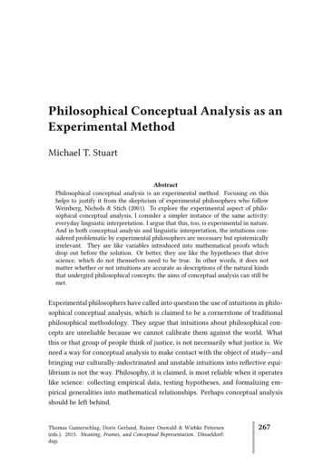
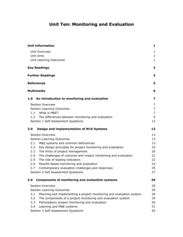
IACSIT International Journal of Engineering and Technology, Vol. 7, No. 3, June 2015R-1234yf was handled in more detail in previous studies[15], [16] and therefore no information related to its mainproperties will be given here. The main objective of thiscontribution is experimentally investigate the performance ofan elevator air conditioner (EAC) prototype, designed andmanufactured at a factory located in Izmir, Turkey. Twodifferent refrigerants, R-134a and the new LGWP refrigerantR-1234yf, have been tested on the prototype without makingany changes on the system. Energy and exergy analyses ofthe system are performed and the obtained results arecompared to each other.related to material compatibility, stability and also miscibilityin oils of R-1234yf. She reported that SAE CRP1234-2 andJAMA results indicated good compatibility and thermalstability with various commercially available commonautomotive materials while R-1234yf was more misciblewith POE lubricants than R-134a. Ikegami et al., [8] used lifecycle climate performance (LCCP) method to evaluate theenvironmental performance of R-1234yf in comparison withR-744. Based on the results reported, the use of R-1234yfwould lead to a 12% decrease in CO2 emissions in 2017 withthe assumption of 43% alternative refrigerant usage. On theother hand, in a report prepared by Kauffeld [9], it is statedthat there are concerns related to the effects of the use ofHFOs (hydrofluoroolefins) on large scale, regarding theenvironment. In a study carried out by Jarahnejad [4], theperformance of R-1234yf was compared to that of R-134a at10 different heat load rates between 1kW and 3.2 kW.According to the test results, R-134a had in average 0-3%higher volumetric cooling capacity while R-1234yf had 0-8%lower volumetric compression work at condensingtemperatures of 30 C and 40 . The COP value of R-134awas in average 2-15% higher than that of R-1234yf. R-134aalso showed better performance in terms of heat transfercoefficient. In another experimental study performed bywell-known automobile manufacturers, the performance ofR-1234yf has been investigated on a vehicle. In the drop-intests, R-1234yf had a COP value of 2.18 while the COP ofR-134a was 2.24. After the optimization of the system(increasing subcooling by 30% and thermal expansion valvesetting from 2 bars to 2.3 bars), R-1234yf reached the level ofR-134a in terms of COP [10]. There are also studies on newdevelopmental refrigerants (DR), which are mainly mixturesof R-1234yf and other refrigerants. The aim of DRs is toincrease the performance of the system while keeping theGWP under a certain level at the same time. Leck [11]developed a theoretical refrigeration cycle model to show theperformance and environmental characteristics of DRs andcompared their capacities and COPs to that of R-410A. Allthe new blends presented a better COP value than that ofR-410A while the capacities and GWP values were lower.Exergy analysis is a very effective tool in evaluatingsystem performance and optimizing energy savings. In thisregard, various studies have been conducted related to heatpumps and refrigeration systems. Hepbasli [12] appliedexergy modeling to a solar assisted domestic hot water tankintegrated ground-source heat pump (GSHP) system. Theexergy efficiencies on a product/fuel basis were found to be72.33% for the GSHP, 14.53% for the solar domestic hotwater system and 44.06% for the whole system. Ahamed etal., [13] reviewed exergy analysis of vapor compressionrefrigeration systems in their study. They investigated theeffect of refrigerant on exergy analysis/parameters, and theeffects of evaporating and condensing temperatures,reference state, lubricant and additives on exergy losses.They concluded that major exergy losses are occurred in thecompressor among the components of the vapor compressionsystem. Özgür et al., [14] theoretically investigated energeticand exergetic performance of R-134a in comparison withR-1234yf. They concluded that there were not any importantdifferences between exergy efficiencies of both refrigerants.II. EXPERIMENTAL SET-UPA. Test FacilityThe experiments have been conducted at the performancetest facility of the factory, as shown in Fig. 1. The test facilityconsists of two separate parts to simulate outdoor and indoorenvironments. The outdoor room dimensions are 5m 14 m 6.5 m while there is a 12 m test car inside, which can bedivided into smaller volumes using separators. Inside theouter room, there are 10 refrigeration devices, each with acapacity of 2.35 kW and a 34.87 kW burner. Using thesedevices, it is possible to reach temperatures between -20 Cand 55 C. In this study, an 11 m3 inner volume has beenused. The outdoor room temperature was set to 35 C 2.Because there were not any temperature and humidity controldevices in the inner room, the tests have been conductedstarting with an indoor temperature of 35 C decreasing withtime. To maintain a relatively smaller decrease, an internalheat gain rate of 1 kW was maintained by using an electricalheater.(a)(b)Fig .1 (a). Outdoor test room (b). Inner test room (with the permission ofSAFKAR INC.).B. Test ProcedureThe performance parameters, namely the pressure drop,the cooling capacity, the energy consumption and the COP,were calculated using the data collected from the refrigerantside. The temperatures of the refrigerant were measuredcontinuously at the inlets and exits of the heat exchangersusing four PT-100 sensors and recorded with a data logger.The pressures at the inlet and outlet of the evaporator weremeasured and recorded every 10 seconds with an electronicmanifold. The pressures at the inlet and exit of the condenserwere measured with an electronic manifold, but recordedmanually every 5 minutes. The indoor and outdoor airtemperatures were also measured with PT-100 sensors andrecorded with the data logger continuously. Themeasurement devices used during the experiments and their255
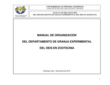
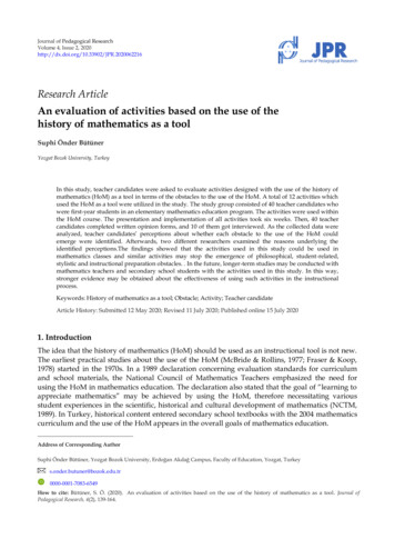
IACSIT International Journal of Engineering and Technology, Vol. 7, No. 3, June 2015uncertainties are given in Table I. The measurement points onthe system and a picture of the prototype mounted on the roofof the test room are given in Fig. 2(a) and Fig. 2(b),respectively.ε comp PT 100Testo 570-2 Digital Manifold(Evaporator inlet and outlet pressures)Testo 557-2 Digital Manifold(Condenser inlet and outlet pressures) 1 h2 h1exdest ,comp(1c)wThe mechanical-electrical losses can be obtained from:exdest ,comp ,mech,el (1 η mη el )welTABLE I: UNCERTAINTIESMeasurement Deviceψ 2 ψ 1Uncertainity(1d)With 0.1 C 0.5%wel 0.5%h2 h1(1e)η mη elThe internal irreversibility due to the fluid friction iscalculated from:ex dest ,comp ,int exdest ,comp exdest ,comp ,mech,el(1f)Condenser:q H h2 h3(a)(b)Fig. 2. (a). Test schematic (b). Prototype mounted on the roof of the inner testroom. Tq exdest ,cond T0 s3 s2 H ψ 2 ψ 3 qH 1 0TH THC. ModellingThe following assumptions are made for energy andexergy analyses of the system. All processes are steady state and steady flow withnegligible potential and kinetic energy effects. The pressure losses in the pipelines connecting thecomponents are negligible, since their lenghts are short. Heat losses/gains between the environment and systemcomponents are ignored. The experimental data used in the calculations areaverage values during the whole test period. Thethermodynamic properties of the refrigerants areobtained using the Refprop software package, developedby NIST [17]. Since there are not any flowmeters installed in thesystem to measure the mass flow rate of the refrigerant,all the obtained results are on the unit mass basis. The mechanical (ηm) and electrical efficiencies (ηel) ofthe compressor are taken to be 0.85 and 0.90,respectively. The power consumptions of the condenser andevaporator fans are assumed to be negligible. High and low temperature are taken as the averages ofthe test period, which are 35 and 27 , respectively. The values for the reference state temperature andpressure are taken to be 30 C and 101.325 kPa,respectively.General energy, entropy and exergy balance equations arereduced to specific equations for each component illustratedin Fig. 2 and are given below [12].Compressor:w h2 h1exdest , comp T0 ( s2 s1 ) ψ 1 ψ 2 w(2a)ε cond exq H (1 T0 / TH ) 1 dest ,condψ 2 ψ 3ψ 2 ψ 3 (2b) (2c)Expansion valve:h3 h4(3a)exdest ,exp T0 (s4 s3 ) ψ 3 ψ 4ε exp (3b)ψ4ψ3(3c)Evaporator:qL h1 h4 qexdest ,evap T0 s1 s 4 LTL ε evap T ψ 4 ψ 1 q L 1 0 TLexqH (T0 TL ) / TL 1 dest ,evapψ 4 ψ 1ψ 4 ψ 1ψ i hi h0 T0 ( si s0 )(4a) (4b)(4c)(5)The COP of the refrigeration cycle can be calculated using(6), while the COP of the system including mechanical andelectrical losses can be determined from (6b):(1a)(1b)COPcycle 256qLw(6a)
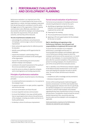
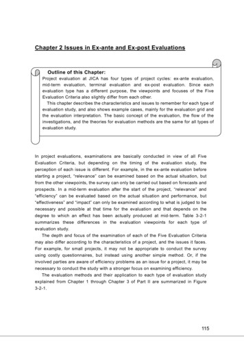
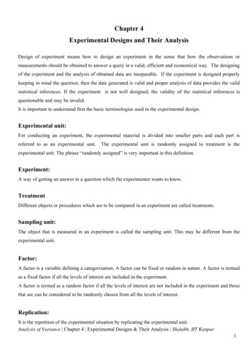
IACSIT International Journal of Engineering and Technology, Vol. 7, No. 3, June 2015COPsystem qLw(6b)Total specific exergy destruction can be derived from:The overall exergy efficiency based on product/fuel basiscan be calculated from:ε cycle specific exergetic product p specific exergetic fuel fiexdest ,tot exdest ,comp exdest ,cond exdest ,exp exdest ,evap (10)III. RESULTS AND DISCUSSION(7a)The pressure values at the inlet and exit of the evaporatorand condenser, the pressure drop in each heat exchanger andthe compression ratio are also calculated and given in TableII, which are based on the average values taken during thewhole test period. The pressure of R-1234yf is slightly higherthan that of R-134a for the evaporator and lower for thecondenser while its compression ratio is approximately 20%lower.Pressure-enthalpy and temperature-entropy diagrams ofboth refrigerants are illustrated and compared to each other inFig. 3 and Fig. 4, respectively. As it can be seen in Fig. 3, thespecific cooling capacity of R-134a is significantly higherthan that of R-1234yf while its specific compression work isslightly lower than that of R-1234yf. The lower compressionwork of R-1234yf causes an improvement in the COP of thesystem. The difference between the COP values of the twosystems is, therefore, within the range of 9%.iThe functional exergy efficiency of the system may also becalculated using:ε func ex4 ex1wel(7b)Van Gool’s improvement potential on unit mass basis isgiven by:ip (1 ε )(exin exout )(8)Relative irreversibility values for each component can beobtained from:RI exdest ,iexdest ,tot(9)TABLE II: AVERAGE PRESSURE VALUES OF THE REFRIGERANTSPressure (kPa)Evap. OutletCond. InletCond. OutletPressure Drop tEvap. 94401341.861331.7958.1610.13.05Table III for both refrigerants, while Table IV presents someenergetic and exergetic data for the system based on thespecific values. The electrical work input (wel) is calculatedfrom (1e) and found to be 61.52 kJ/kg for R-134a and 53.75for R-1234yf. The greatest irreversibility/exergy destructionoccurs on the compressor of the system for both refrigerantsand it is followed by the condenser, evaporator and theexpansion valve. The irreversibility related to expansionvalve is relatively very small and it is due to the pressure dropof the refrigerant. In terms of exergy efficiencies thefollowing inequality can be written for both refrigerants:Fig. 3. Ln P – h diagram comparison of R-134a and R-1234yf.εexp εcomp εcond εevapFig. 4. T – s diagram diagram comparison of R-134a and R-1234yf.Temperature and pressure values and correspondingspecific enthalpy, entropy and exergy values are listed inFig. 5. Exergy flow and loss (Grasmann) diagram for R-134a.257
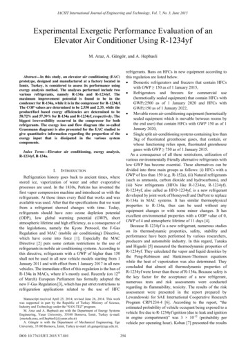
IACSIT International Journal of Engineering and Technology, Vol. 7, No. 3, June 2015The overall exergy efficiency values on product/fuel basisfor R-134a and R-1234yf are found to be 58.72% and57.39%, respectively, while the functional exergyefficiencies are determined as 19.59% for R-134a and17.22% for R-1234yf.Van Gool’s improvement potential given in (8) iscalculated for each component of the refrigeration systemand the results are listed in Table IV. It is found that forR-134a, the compressor has the highest exergeticimprovement potential (15.45 kJ/kg) followed by thecondenser, evaporator and expansion valve with 10.25, 9.13and 0.13 kJ/kg, respectively. Similarly, the highest ip valuefor R-1234yf occurred in the compressor due to its highexergy destruction. The evaporator has an exergeticimprovement potential of 6.92 kJ/kg, which is very close tothe value of the condenser (6.56 kJ/kg). The ip value of theexpansion valve for R-1234yf is found to be 0.12 kJ/kg.One way to see the results of exergy analysis is to drawexergy flow and loss (Grassmann) diagrams for the systemsstudied. In this regard, the two Grasmann diagrams are drawnfor an exergy input of 100% and illustrated in Fig. 5 and Fig.6 for R-134a and R-1234yf, escriptionPhaseFluidTemperature,( e,( C)TABLE III: DATA USED IN THE mp. 31.0953.8742.5640.35IV. CONCLUSIONSAn EAC unit is experimentally investigated and it’sperformance is evaluated using exergy analyses. The specificexergy destructions, exergy efficiencies, exergeticimprovement potentials and relative irreversibilities areR-1234yf30.00440.00TABLE IV: RESULTS OF THE ENERGY AND EXERGY ANALYSES BASED ONSPECIFIC VALUESFluidR-134aExpansionEvaporator Compressor J/kg)Exergetic 61.5216.1847.49(kJ/kg)Exergy destruction10.4930.8312.882.46(kJ/kg)Exergy 54.4222.734.33irreversibility (%)2.55COP of the systemExergy efficiency of58.72the cycle (%)Functional exergy19.59efficiency of thesystem (%)FluidR-1234yfExpansionEvaporator Compressor J/kg)Exergetic 3.7511.3142.56(kJ/kg)Exergy destruction8.0130.978.622.21(kJ/kg)Exergy rsibility16.0762.1917.304.44(%)2.33COP of the systemExergy efficiency of57.39the cycle (%)Functional exergy17.22efficiency of thesystem (%)Fig. 6. Exergy flow and loss (Grasmann) diagram for R-1234yf.State101.32514.26258
IACSIT International Journal of Engineering and Technology, Vol. 7, No. 3, June 2015calculated for each component and comparisons are madebetween the refrigerants.Some concluding remarks can be listed as follows:The legislations related to the contribution of the existingrefrigerants to global warming make it necessary to usealternative refrigerants with low GWP, such as R-1234yf.R-134a showed a slightly better performance in drop-intests. The cooling effect of R-1234yf is found to beapproximately 20% lower, while the compression work ofR-134a is about 13% higher than that of R-1234yf on thebasis of the specific enthalpy values. The lower compressionwork causes an improvement in the COP. The COP values ofR-134a and R-1233yf are 2.55 and 2.33, respectively.R-1234yf has higher pressure values than R-134a for bothheat exchangers. While the pressure drop values in theevaporator and condenser are 58.16 kPa and 10.1 kPa forR-1234yf, they are 45 and 8.7 for R-134a, respectively.No important difference is found between the exergyefficiencies of the refrigerants. The exergetic efficiencyvalues based on product/fuel basis are found to be 58.72%and 57.39% for R-134a and R-1234yf, respectively. On theother hand the functional exergy efficiencies are 19.59% forR-134a and 17.22% for R-1234yf.For a further work, it is recommended to conduct moretests with a refrigerant flowmeter to get the exergeticparameters on rate basis. Additionally, exergoenvironmentalanalysis can be performed to assess the environmentalbenefits of R-1234yf in comparison with R-134a.Exergoecomomic analysis may also be performed to showthe effect of the high cost of R-1234yf, which is due to theinsufficient production capacity.[8][9][10][11][12][13][14][15][16][17]M. Araz was born in Karaman, Turkey on August 23,1986. He received B.S. degree in mechanical engineeringfrom Ege University, Turkey in 2010, M.S degree in 2013and is currently a Ph.D. student in mechanicalEngineering at Ege University.He completed his military service in 2011. He has beenworking as a research assistant in the Energy SystemsEngineering Department of Yaşar University, in İzmir, since October, 2012.He has worked as scholarship student in the project entitled “Design of anElevator Air Conditioning Unit Using R-1234yf”, which is supported by theRepublic of Turkey Ministry of Science, Industry and Technology. Hisresearch interests are low global warming potential (LGWP) refrigerants, airconditioning systems, refrigeration technologies and clean energy systems.Mr. Araz is a member of Union of Chambers of Turkish Engineers andArchitects the Chamber of Mechanical Engineers.ACKNOWLEDGMENTThe authors are very grateful to the Republic of TurkeyMinistry of Science, Industry and Technology for the supportgiven to this project through the program called “SAN-TEZ”.They also thank DuPont for providing a free sample ofR-1234yf and R&D personnel of SAFKAR INC., Izmir,Turkey for their support and help during performing the tests.REFERENCES[1][2][3][4][5][6][7]Systems Conference and Exhibition (VTMS10), Willmington, DE, 2011,pp. 11-18.T. Ikegami, M. Iguchi, K. Aoki, and K. Iijima, “New refrigerantsevaluation results,” presented at the SAE 2008 Alternate RefrigerantSystems Symposium, Arizona, 2008.M. Kauffeld, Availability of Low GWP Alternatives toHFCs-Feasibility of an early Phase-Out of HFCs by 2020,Environmental Investigation Agency, Inc., 2012.R. Monforte, B. Rose, and J. -M. L’Huillier, “Updated situation aboutalternate refrigerant evaluation,” presented at the SAE 2008 AlternateRefrigerant Systems Symposium, Scottsdale, AZ, 2008.T. J. Leck, “New high performance low GWP refrigerants forstationary AC and refrigeration,” in Proc. International Refrigerationand Air Conditioning Conference, Purdue, 2011, pp. 1-8.A. Hepbasli, “Exergetic modeling and assessment of solar assisteddomestic hot water tank integrated ground-source heat pump systemsfor residences,” Energy and Buildings, vol. 39, pp. 1211-1217, 2007.J. U. Ahamed, R. Saidur, and H. H. Masjuki, “A review on exergyanalysis of vapor compression refrigeration system,” Renewable andSustainable Energy Reviews, vol. 15, pp. 1593-1600, 2011.A. E. Özgür, A. Kabul, and Ö. Kizilkan, “Exergy analysis ofrefrigeration systems using an alternative refrigerant (HFO-1234yf) toR-134a,” International Journal of Low-Carbon Technologies, vol. 9,pp. 1-7, 2012.M. Araz, A. Güngör, H. Yaldırak, and H. G. Özcan, “Utilizationpossibilities of R-1234yf in automobile industry,” in Proc. 1st NationalAir Conditioning Refrigeration Education Symposium and Exhibition,2012. (in Turkish)M. Araz, A. Güngör, and A. Hepbasli, “Assessment of the use of LowGlobal Warming Potential (LGWP) refrigerants in refrigerationapplications,” in Proc. 11th National HVAC and Sanitary Conventionand Exhibition (TESKON 2013), 2013, vol. 1, pp. 573-604. (inTurkish)E. W. Lemmon, M. L. Huber, and M. O. McLinden, NIST StandardReference Database 23: Reference Fluid Thermodynamic andTransport Properties-REFPROP, version 9.1, National Institute ofStandards and Technology, Standard Reference Data Program,Gaithersburg, 2013.J. M. Calm, “The next generation of refrigerants – Historical review,considerations, and outlook,” International Journal of Refrigeration,vol. 31, pp. 1123-1133, 2006.Directive 2006/40/EC of the European Parliament and of the Councilof 17 May 2006 Relating To Emissions from Air-ConditioningSystems in Motor Vehicles And Amending Council Directive70/156/EEC, Office Journal of the Europian Union, 2006.The European Parliament. European Parliament legislative resolutionof 12 March 2014 on the proposal for a regulation of the EuropeanParliament and of the Council on fluorinated greenhouse gases(COM(2012)0643 – C7-0370/2012 – 2012/0305(COD)). ies/f-gas/legislation/docs/fluorinated greenhouse gases en.pdf.M. Jarahnejad, “New low GWP synthetic refrigerants,” Master ofScience Thesis, Industrial Engineering and Management, KTH,Stockholm, 2012.K. Tanaka and Y. Higashi, “Thermodynamic properties ofHFO-1234yf (2, 3, 3, 3-tetrafluoropropene),” International Journal ofRefrigeration, vol. 33, pp. 474-479, 2010.T. A. Lewandowski, Additional risk Assessment of AlternativeRefrigerant R-1234yf, 2013, pp. 1-29.M. Koban, “Automotive material investigation with low GWPrefrigerant HFO-1234yf,” in Proc. Vehicle Thermal ManagementA. Güngör was born in Elazığ, Turkey in 1955 and hastwo daughters. He received B.S in mechanicalengineering in 1977 and M.S. in 1978 from theDepartment of Mechanical Engineering of EgeUniversity, Turkey and a Ph.D. in 1985 from the SolarEnergy Institute of the same university.He conducted research at the Brace Research Institute,Canada in 1986 for 6 months. He became an associateprofessor in the field of Heat and Mass Transfer in 1989 and a professor in1996 at Ege University. He has worked in different institutions includingDepartment of Mechanical Engineering of Dokuz Eylül University, SolarEnergy Institute and Department of Mechanical Engineering of EgeUniversity since 1978. He was the head of the Department of MechanicalEngineering of Ege University between 1997 and 2012 and is still serving atthe same department as the head of Thermodynamics Division. His researchinterests are air conditioning, solar thermal energy applications, refrigerationtechnique, absorption and adsorption refrigeration technologies, dryingtechnique, heat pipes, thermodynamics and heat and mass transferapplications.Professor Güngör is a member of Union of Chambers of TurkishEngineers and Architects the Chamber of Mechanical Engineers, TurkishHeat Science and Technique Association and ASHRAE.259
IACSIT International Journal of Engineering and Technology, Vol. 7, No. 3, June 2015A. Hepbasli was born in Izmir, Turkey on June 27, 1958.He received B.S. (first class honor) in mechanicalengineering from Selcuk University (SU), Turkey in1980, M.S. from Istanbul Technical University ofIstanbul, Turkey in 1985 and a Ph.D. in mechanicalengineering from Selcuk University in 1990 while hewas working in industry. He joined Ege University in1996 after about a ten-year period in industry at different positions and aone-year period at Izmir Branch Office of Chamber of Mechanical Engineersas a consultant. He has been appointed as the Head of Energy SystemsEngineering Department at Yaşar University in Izmir, Turkey sinceSeptember 2012. He is the author and co-author of over 530 papers (over 250260SCI-based papers with an h-index of 34) on a national and international basisas well as several national and international books and book chapters. Hisresearch has been involved with energy, exergy, exergoeconomic andexergoenvironmental analyses and assessments of energy-related systems,energy/exergy efficiency and management, clean energy technologies,ground-source heat pumps, utilization and potential of renewable energysources and sustainable energy technologies. He has served as a consultantfor industry in cases involving his research area and is also a member in theinternational advisory board of eight prestigious energy-related journals, andan associate editor of Journal of Energy Engineering (ASCE) while alsoserving many energy journals and industrial projects as a reviewer.
an elevator air conditioner (EAC) prototype, designed and manufactured at a factory located in Izmir, Turkey. Two different refrigerants, R-134a and the new LGWP refrigerant R-1234yf, have been tested on the prototype without making any changes on the system. Energy and exergy analyses of the system are performed and the obtained results are