Transcription
THE STRUT-AND-TIE MODELOF CONCRETE STRUCTURESByDr. C. C. Fu, Ph.D., P.E,The BEST CenterUniversity of MarylandPresented toThe Maryland State Highway AdministrationAugust 21, 2001
IntroductionThe Strut-and-Tie is a unified approach thatconsiders all load effects (M, N, V, T)simultaneouslyThe Strut-and-Tie model approach evolves as oneof the most useful design methods for shear criticalstructures and for other disturbed regions inconcrete structuresThe model provides a rational approach byrepresenting a complex structural member with anappropriate simplified truss modelsThere is no single, unique STM for most designsituations encountered. There are, however, sometechniques and rules, which help the designer,develop an appropriate model
History and SpecificationsThe subject was presented by Schlaich et al(1987) and also contained in the texts byCollins and Mitchell (1991) and MacGregor(1992)One form of the STM has been introduced inthe new AASHTO LRFD Specifications (1994),which is its first appearance in a designspecification in the USIt will be included in ACI 318-02 Appendix A
Bernoulli HypothesisBernoulli hypothesis states that: " Planesection remain plane after bending "Bernoulli's hypothesis facilitates the flexuraldesign of reinforced concrete structures byallowing a linear strain distribution for allloading stages, including ultimate flexuralcapacityN.A.
St. Venant’s PrincipleSt. Venant's Principle states that: " Thelocalized effects caused by any loadacting on the body will dissipate orsmooth out within regions that aresufficiently away from the location of theload "
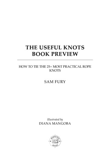
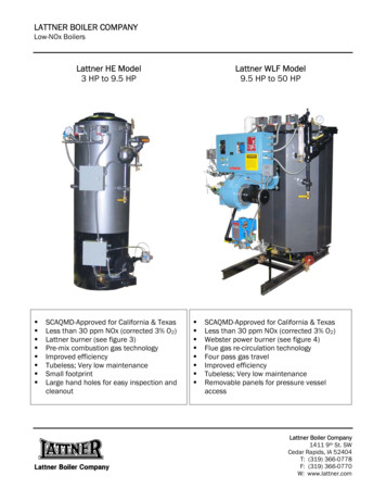
B- & DRegionsforVariousTypes ofMembers
Design of B & D RegionsThe design of B (Bernoulli or Beam) region iswell understood and the entire flexuralbehavior can be predicted by simplecalculationEven for the most recurrent cases of D(Disturbed or Discontinuity) regions (such asdeep beams or corbels), engineers' ability topredict capacity is either poor (empirical) orrequires substantial computation effort (finiteelement analysis) to reach an accurateestimation of capacity
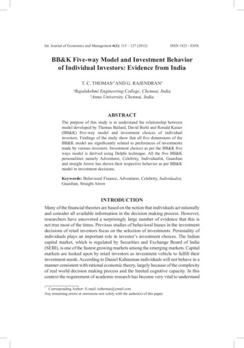
STMforSimpleSpanBeam
Feasible Inclined Angle θSwiss Code: 0.5 Cot θ 2.0 (θ 26 to 64 )European Code: 3/5 Cot θ 5/3 (θ 31 to 59 )Collin’s & Mitchellsθmin 10 110(Vu/[φfc′bwjd]) degθmax 90 - θmin degACI 2002: θmin 25 ; (25 θrecom 65 here)If small θ is assumed in the truss model, thecompression strength of the inclined strut isdecreased.
STM of a Deep BeamACI Section 10.7.1 For Deep Beam:L/d 5/2 for continuous span; 5/4 for simple spanACI Section 11.8: L/d 5 (Shear requirement)
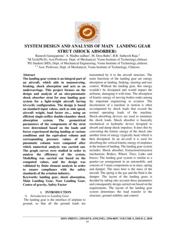
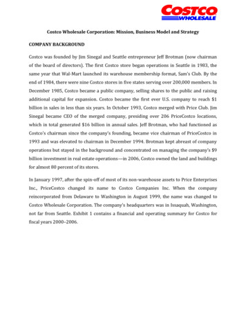
DeepBeamStressand ItsSTMModel
Transitionfrom Deep Beam to Beam
STM Modelfor aTwo-spanContinuousBeam
Basic ConceptsStrut-and-Tie Model: A conceptual frameworkwhere the stress distribution in a structure isidealized as a system ofStrutCompression ConcreteMemberTie or TensionStirrup MemberReinforcementNodeConcreteConnection
Examples of STM Models
Strut Angle of STM ModelA STM developed with struts parallel to theorientation of initial cracking will behave very wellA truss formulated in this manner also will make themost efficient use of the concrete because theultimate mechanism does not require reorientation ofthe struts
Lower Bound Theoremof PlasticityA stress field that satisfies equilibriumand does not violate yield criteria at anypoint provides a lower-bound estimateof capacity of elastic-perfectly plasticmaterialsFor this to be true, crushing of concrete(struts and nodes) does not occur priorto yielding of reinforcement (ties orstirrups)
Limitation of The Truss AnalogyThe theoretical basis of the truss analogy isthe lower bound theorem of plasticityHowever, concrete has a limited capacity tosustain plastic deformation and is not anelastic-perfectly plastic materialAASHTO LRFD Specifications adopted thecompression theory to limit the compressivestress for struts with the consideration of thecondition of the compressed concrete atultimate
PrerequisitesEquilibrium must be maintainedTension in concrete is neglectedForces in struts and ties are uni-axialExternal forces apply at nodesPrestressing is treated as a loadDetailing for adequate anchorage
Problemsin STM Applications1.How to construct a Strut-and-Tiemodel?2.If a truss can be formulated, is itadequate or is there a better one?3.If there are two or more trusses for thesame structure, which one is better?
StrutsA. Compression struts fulfill two functions inthe STM:1. They serve as the compression chord ofthe truss mechanism which resistsmoment2. They serve as the diagonal struts whichtransfer shear to the supportsB. Diagonal struts are generally orientedparallel to the expected axis of cracking
Types of StrutsThere are three types of struts that will bediscussed:1. The simplest type is the “prism” which has aconstant width2. The second form is the “bottle” in which thestrut expands or contracts along its length3. The final type is the “fan” where an array ofstruts with varying inclination meet at orradiate from a single node
Three Types of Struts
Compression Struts
TiesTensions ties include stirrups, longitudinal(tension chord) reinforcement, and anyspecial detail reinforcementA critical consideration in the detailing of theSTM is the provision of adequate anchoragefor the reinforcementIf adequate development is not provided, abrittle anchorage failure would be likely at aload below the anticipated ultimate capacity
NodesNodes are the connections of the STM,i.e., the locations at which struts andties convergeAnother way of describing a node is thelocation at which forces are redirectedwithin a STM
Type ofSingularNodes(Schlaichet al1987)
Idealized Forcesat Nodal Zones
SingularandSmearedNodes
STM Model Design ConceptThe successful use of the STM requires anunderstanding of basic member behavior andinformed engineering judgmentIn reality, there is almost an art to theappropriate use of this techniqueThe STM is definitely a design tool forthinking engineers, not a cookbook analysisprocedureThe process of developing an STM for amember is basically an iterative, graphicalprocedure
STMModelDesignFlowChart
Methods forFormulating STM ModelElastic Analysis based on StressTrajectoriesLoad Path ApproachStandard Model
ElasticAnalysisfor theSTMModel A
Elastic Analysisfor the STM Models B & C
Elastic Analysis ApproachProcedures1. Isolate D-regions2. Complete the internal stresses on theboundaries of the element3. Subdivide the boundary and computethe force resultants on each sub-length4. Draw a truss to transmit the forces fromboundary to boundary of the D-region5. Check the stresses in the individualmembers in the truss
STMModel CExampleusingElasticAnalysis
STM Model C ExampleReinforcement
LoadPathApproach(Schlaichet al.1987)
Example ofDeterminingSTM ModelGeometry
Factors Affecting Size ofCompression StrutLocation and distribution ofreinforcement (tie) and its anchorageSize and location of bearing
Nodal ZonesThese dimensions are determined for eachelement using(1)(2)(3)(4)(5)thethethethethegeometry of the member and the STM,size of bearings,size of loaded areas,location and distribution of reinforcement, andsize of tendon anchorages, if anyStruts and ties should be dimensioned so thatthe stresses within nodes are hydrostatic, i.e.,the stress on each face of the node should bethe same
Hydrostatic Nodal Zones
Cracking of Compression Strutbef a λ/6T C(1-a/bef)/4
STM Models A & B forAnchorage Zones
STM Models C & D forAnchorage Zones
Examplesof Goodand PoorSTMModels Good Model is more closely approaches to the elastic stress trajectoriesPoor model requires large deformation before the tie can yield; violate therule that concrete has a limited capacity to sustain plastic deformation
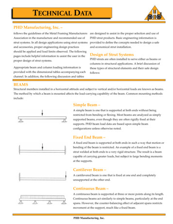
Nonlinear finite element comparison ofthree possible models of a short cantilever(d) behaves almost elasticallyuntil anticipated failure load(c) requires the largestamount of plasticdeformation; thus it is morelikely to collapse beforereaching the failure load level
STM Model for a Ledged End
Beam-Column Opening Joints
Efficiency of Opening Joints
T-Joints
Concentrated Load on aBearing Wall
STMModels(a)Tensile Flangew/Opening(b)CompressionFlangew/Opening
STM Models(c) Web supported by Diaphragm(d) Pier and Diaphragm w/Single Support
STM Models(e) Other Model for Diaphragm(f) Pier and Diaphragm w/Two Supports
STMModels(g) Piers ona Pile Cap
Examples of STM Models &Reinforcement (Schlaich et al 1987)
LimitingStressesfor TrussElements
Limiting Compressive Stress in StrutAASHTO LRFD 5.6.3.3.3f c'f cu 0.85 f c'0.8 170ε1where:e1 (es 0.002) cot2 a sfcu the limiting compressive stressas the smallest angle between the compressivestrut and adjoining tension ties (DEG)es the tensile strain in the concrete in thedirection of the tension tie (IN/IN)
Simplified Values for Limiting CompressiveStress in Strut, fcu (Schlaich et al. 1987)For an undisturbed and uniaxial state of compressive stress:fcu 1.0 (0.85 fc?) 0.85 fc?If tensile strains in the cross direction or transverse tensilereinforcement may cause cracking parallel to the strut withnormal crack width:fcu 0.8 (0.85 fc?) 0.68 fc?As above for skew cracking or skew reinforcement:fcu 0.6 (0.85 fc?) 0.51 fc?For skew cracks with extraordinary crack width – such cracksmust be expected if modeling of the struts departssignificantly from the theory of elasticity’s flow of internalforces:fcu 0.4 (0.85 fc?) 0.34 fc?
Strength of Compressive StrutAASHTO LRFD 5.6.3.3.3Pr F Pn(LRFD 5.6.3.2-1)Pn fcu Acs(LRFD 5.6.3.3.1-1)where:F 0.70 for compression in strut-and-tie models(LRFD 5.5.4.2.1)Acs effective cross-sectional area of strut(LRFD 5.6.3.3.2)
ACI 2002 STM ModelDesign of struts, ties, and nodal zones shall be based on:φFn FuThe nominal compressive strength of a strut withoutlongitudinal reinforcement:Fns f cu AcThe effective compressive strength of the concretein a strut is:f cu 0.85 β s f c'
ACI 2002 STM ModelThe strength of a longitudinally reinforced strut is:Fns f cu Ac As' f s'The nominal strength of a tie shall be taken as:Fnt Ast f y A ps ( f se f p )The nominal compression strength of a nodal zone shall be:Fnn f cu An
Findings of STM ModelThe STM formulation that requires the leastvolume of steel will be the solution that bestmodels the behavior of a concrete memberThis approach holds great promise for DOTsand design offices which could develop orobtain standard STMs for certain commonlyencountered situationsStandard reinforcement details based on anSTM could be developed for common situationsThe STM then could be reviewed and revised ifany parameters change
Hammerhead Pier Example
Hammerhead Pier STM Model
Spreadsheet Calculation of STMModel ExamplesAbutment on Pile Model ExampleWalled Pier Model Example
AASHTO LRFD 5.6.3.3.3 ' 1 ' 0.85 0.8 170 c c cu f f f e where: e 1 (e s 0.002) cot2 a s f cu the limiting compressive stress a s the smallest angle between the compressive strut and adjoining tension ties (DEG) e s the tensile strain in the concrete in the direction of the tension tie (IN/IN)