Transcription
DRAFTKvaser U100 User’s GuideCopyright 2020-2021 Kvaser AB, Mölndal, Swedenhttps://www.kvaser.comPrinted Thursday 21st January, 2021We believe that the information contained herein was accurate in all respects at the time of printing.Kvaser AB cannot, however, assume any responsibility for errors or omissions in this text. Also notethat the information in this document is subject to change without notice and should not be construedas a commitment by Kvaser AB.
Kvaser U100 User’s Guide2 (22)DRAFT(This page is intentionally left blank.)Kvaser AB, Mölndal, Sweden — www.kvaser.com
3 (22)Kvaser U100 User’s GuideContents1 About this manual4.55566DRAFT2 Introduction2.1 Welcome to Kvaser U100 . . . . . . . .2.2 Major features . . . . . . . . . . . . . .2.3 Interface . . . . . . . . . . . . . . . . .2.4 Additional software and documentation3 Kvaser U100 hardware3.1 Hardware installation3.2 USB connection . . .3.3 CAN channels . . . .3.4 Power supply . . . .3.5 LED Indicators . . . .3.6 Troubleshooting . . .77788884 Appendices4.1 Definitions of LED states and colors . . . .4.2 Definitions of Information types and States4.3 Interface mode . . . . . . . . . . . . . . .4.4 Technical data . . . . . . . . . . . . . . . .4.5 USB connector options . . . . . . . . . . .4.6 CAN connector options . . . . . . . . . . .4.7 CAN bus termination . . . . . . . . . . . .4.8 Updating the firmware . . . . . . . . . . . .99111112131414155 Safety Instructions5.1 Intended Use . . . . . . . . . . . . . . . . . . . . . . . . . . . . . .5.2 Usage Warning . . . . . . . . . . . . . . . . . . . . . . . . . . . . .1616166 Disposal and Recycling Information177 Legal Acknowledgements7.1 EU Regulatory Compliance . . . . . . . . . . . . . . . . . . . . . . .7.2 FCC Regulatory Compliance . . . . . . . . . . . . . . . . . . . . . .7.3 Patents, Copyrights and Trademarks . . . . . . . . . . . . . . . . . .191920218 Document Revision History22.Kvaser AB, Mölndal, Sweden — www.kvaser.com
Kvaser U100 User’s Guide14 (22)About this manualDRAFTThis manual is intended for Kvaser U100 users. This document contains adescription of the hardware’s properties and general instructions for connecting thedevice to a computer.Kvaser AB, Mölndal, Sweden — www.kvaser.com
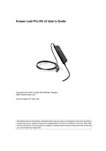
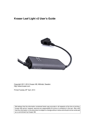
5 (22)Kvaser U100 User’s Guide2IntroductionThis section will describe the functions and features of the Kvaser U100.Welcome to Kvaser U100DRAFT2.1Figure 1: Kvaser U100 with D-SUB CAN connectorKvaser U100 is a small, yet powerful, CAN to USB interface. It provides real-timetransmission and reception of standard and extended CAN messages on the buswith a high timestamp precision, and is compatible with applications that useKvaser’s CANlib.This guide applies to Kvaser U100 devices listed in Table 1.DeviceProduct NumberKvaser U10073-30130-01173-1Table 1: Kvaser U100 devices, with Product numbers.2.2Major featuresKvaser AB, Mölndal, Sweden — www.kvaser.com
Kvaser U100 User’s Guide6 (22) USB CAN interface. Powered through the USB connector. Supports CAN FD, up to 8 Mbit/s (with correct physical layer implementation). Supports both 11-bit (CAN 2.0A) and 29-bit (CAN 2.0B active) identifiers. Lightweight robust housing made of glass fibre reinforced polyamideDRAFTovermolded with TPE. Intuitive LED UI. Reinforced galvanic isolation, design validated with 5000 VAC rms applied for60 s. Industrial grade temperature range, 40 C to 85 C. 20 000 msg/s, each timestamped with a resolution of 100 µs. Fully compatible with applications written for other Kvaser CAN hardwarewith Kvaser CANlib. Support for SocketCAN. Fully compatible with J1939, CANopen, NMEA 2000 R and DeviceNet. IP67 rating. A selection of different cables/connectors for the CAN connection.2.3InterfaceKvaser U100 provides a CAN bus interface through a standard USB interface.2.4Additional software and documentationThe Kvaser CANlib SDK includes everything you need in order to develop softwareapplications interacting with Kvaser CAN hardware. The SDK contains fulldocumentation and many sample programs, written in C, C , C#, Delphi, Pythonand Visual Basic. Kvaser CAN hardware is built around the same commonsoftware API. Applications developed using one device type will run withoutmodification on other device types.The latest versions of documentation, software and drivers can be downloaded forfree at www.kvaser.com/download.Kvaser AB, Mölndal, Sweden — www.kvaser.com
7 (22)Kvaser U100 User’s Guide3Kvaser U100 hardwareIn this section you can read more about the CAN channels, power supply and LEDindicators.3.1Hardware installationDRAFTThe Kvaser U100 may be inserted in any free USB socket on the host computer.You do not need to switch the power off before inserting or removing the device.For the Kvaser U100 to communicate with the host computer, a compatible versionof the Kvaser driver and firmware must be installed.The driver is installed by running the file kvaser drivers setup.exe. Forinstructions on how to update the firmware, see Section 4.8, Updating thefirmware, on Page 15. The latest version of the driver and firmware can bedownloaded from www.kvaser.com/download.The firmware is downloaded and installed directly on the Kvaser U100 and thedriver is installed on the host computer. After the driver has been installed on thehost computer, the firmware may then be downloaded and installed on the KvaserU100.DeviceFirmwareWindows driverLinux driverKvaser U100v3.22.578v5.34 (kcany)v5.34 (mhydra)Table 2: Kvaser U100 devices and requirements on minimal version of firmware anddrivers.3.2USB connectionThe Kvaser U100 is connected to a PC using USB. See Section 4.5, USBconnector options, on Page 13 for more information.Connect the device to your computer using any high quality USB 2.0 certifiedcable. The maximum USB cable length is 5 m ( 16 ft). If you need a longer cable,you can use USB hubs or USB extension cables with a built-in hub. By chaining upto 5 hubs, you can achieve an effective cable length of up to 25 m ( 82 ft).As USB cables become longer they are more sensitive to EMI,because they make a longer antenna that can pick up morenoise. These issues can be mitigated by using higher qualitycables with better shielding. Thicker cables tend to be better thanthin ones, and braided shielding tends to be more reliable thanonly foil. Furthermore, longer cables may introduce signaldegradation and timing issues that, if necessary, can be mitigatedusing shorter cable segments combined with hubs that amplifythe signal and handle delays on a per-cable basis.Kvaser AB, Mölndal, Sweden — www.kvaser.com
Kvaser U100 User’s Guide3.38 (22)CAN channelsThe Kvaser U100 has one CAN Hi-Speed channel. See Section 4.6, CANconnector options, on Page 14 for more information.3.4Power supplyDRAFTThe Kvaser U100 is powered through the USB connector.3.5LED IndicatorsThe Kvaser U100 has one Tx LED Bar and one Rx LED Bar as shown in Figure 2on Page 9, Figure 3 on Page 10. Their functions are described in Section 4.2,Definitions of Information types and States, on Page 11.3.6TroubleshootingUse “Kvaser Device Guide” in the Control Panel to verify that the computer cancommunicate with the Kvaser U100. If the firmware version shown is all zeros,there are communication problems. If the LED Bar or the status indication is notflashing or does not light up at all, check the power supply.Kvaser AB, Mölndal, Sweden — www.kvaser.com
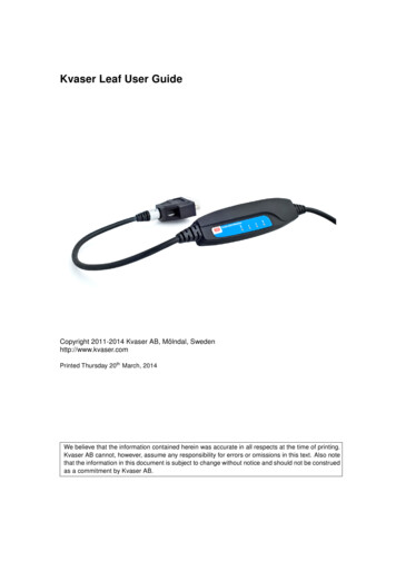
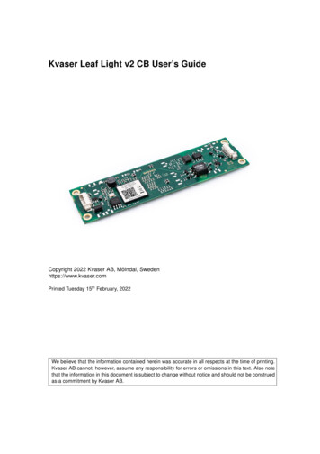
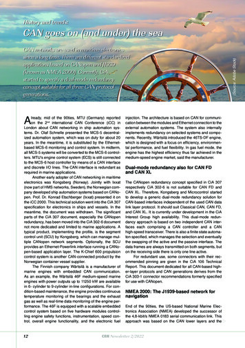
Kvaser U100 User’s Guide49 (22)AppendicesIn this section you will find technical information about the Kvaser U100 and itsconnectors.4.1Definitions of LED states and colorsDRAFTThe Kvaser U100 has one Tx LED Bar and one Rx LED Bar. Each LED Bar has astatus area, the Tx LED Bar has a status area towards the USB end of the bar, andthe Rx LED bar has a status area towards the CAN end of the bar. This is shown inFigure 2.Figure 2: The Tx and Rx LED bars on the Kvaser U100 includes status areas.The Tx LED bar lit area grows from the USB end of the LED bar towards the CANend of the bar as CAN Tx traffic is increased. Likewise, the Rx LED bar lit areagrows from the CAN end of the LED bar towards the USB end of the bar as themessage rate of the received traffic is increased, see Figure 3 on Page 10. In thisexample the unit is transmitting data, which shows a yellow Tx status area. NoCAN traffic is received and as such the Rx status area is green.The total size of the LED bars are indicating the current bus load, e.g. Figure 3 onPage 10 shows only receiving CAN messages at 50% bus load. Figure 4 onPage 10 shows two different bus load conditions. The image on the left shows theunit transmitting and receiving data corresponding to 50% bus load in eachdirection for a total of 100% bus load. The image on the right shows the unittransmitting data corresponding to 100% bus load.Kvaser AB, Mölndal, Sweden — www.kvaser.com
10 (22)DRAFTKvaser U100 User’s GuideFigure 3: The Tx LED bar lights up from the USB side to the CAN side of the unit,while the Rx LED bar lights up from the CAN side to the USB side of the unit.Figure 4: The total size of the LED Bars is proportional to the bus load. Bothimages indicate a bus load of 100%.Kvaser AB, Mölndal, Sweden — www.kvaser.com
11 (22)Kvaser U100 User’s Guide4.2Definitions of Information types and StatesA Kvaser U100 device has two traffic LED bars where part of each LED bar is alsoused as a status area. Different colors are used for different types of informationand different blink patterns define the current state, see Table 3 and Table 4.Information AlertBlueSystemTable 3: Different types of information.StateDefinitionOffThe indicator is off and no light is emitted.Slow BlinkThe indicator is repeatedly turned on and off. The on and off phases are equal intime.Fast BlinkThe indicator is repeatedly turned on and off but with a higher frequency than SlowBlink. The on and off times are still equal.OnThe indicator is constantly emitting light.DynamicThe indicator is moving and/or increasing/decreasing in size.Table 4: Definitions of the indicator states.4.3Interface modeThe device is in interface mode when connected to the PC via USB. If the statusarea is presenting a steady green light, the device is in interface mode and isworking correctly. When connected to the computer for the first time, the statusarea will Fast Blink with blue light until the Kvaser Driver is installed and the devicehas automatically received a USB configuration. Table 5 summarises theinformation shown in interface mode.DescriptionStatus areaLED barPower is onOn (Green)-CAN overrunOn (Red)-CAN channel is error passiveFast Blink (Red)-Firmware updateSlow Blink (Blue)-Waiting for USB configurationFast Blink (Blue)-Error frameOn (Red)On (Red)CAN channel trafficOn (Yellow)Dynamic (Yellow)Locate hardwareSlow Blink (White)Slow Blink (White)Table 5: LED inidications in interface mode.Kvaser AB, Mölndal, Sweden — www.kvaser.com
Kvaser U100 User’s Guide4.412 (22)Technical dataIn Table 6 on Page 12 below you will find the Kvaser U100’s technicalspecifications.1CAN TransceiversADM3055E (Compliant with ISO 11898-2)CAN ControllerBuilt into the processor.DRAFTCAN ChannelsGalvanic isolationYes, reinforced. Design validated with 5000 VAC rms applied for 60 s.CAN Bit Rate10 kbit/s to 1 Mbit/sCAN FD Bit RateUp to 8 Mbit/s (with correct physical layer implementation).Time stamp resolution100 µsMax message rate20 000 msg/s per channelError Frame DetectionYesError Frame GenerationNoSilent modeNoKvaser MagiSyncNoPC interfaceUSB 2.0Power consumptionTypical 250 mAHardware configurationDone by software (Plug & Play)Software requirementsWindows (7 or later), LinuxDimensions38 x 128 x 26 mm for bodyCable lengthUSB 1.0 m, CAN 0.3 mWeight167 g with default connectorsOperating temperature 40 C to 85 CStorage temperature 40 C to 85 CRelative humidity0 % to 85 % (non-condensing)IP RatingIP67Table 6: Technical SpecificationsKvaser AB, Mölndal, Sweden — www.kvaser.com
Kvaser U100 User’s Guide4.513 (22)USB connector optionsThis section describes the PC connector options available for Kvaser U100.4.5.1USB-A connector (Default)DRAFTThe default option for the Kvaser U100 is a standard USB type “A” connector.Figure 5: A standard USB type “A” connector.Kvaser AB, Mölndal, Sweden — www.kvaser.com
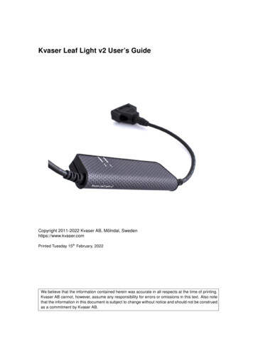
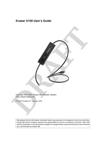
Kvaser U100 User’s Guide4.614 (22)CAN connector optionsThis section describes the CAN connector options available for Kvaser U100.4.6.19-pin D-SUB connector (Default)DRAFTThe default option for the Kvaser U100 is the 9-pin D-SUB connector (seeFigure 7) which has the pinout described in Table 7.Figure 6: 9-pin D-SUB CAN connector.Figure 7: The D-SUB 9 connector pinout.D-SUB pinFunction1Not connected2CAN L3GND4Not connected5Shield6Not connected7CAN H8Not connected9Not connectedTable 7: Configuration of the 9-pin D-SUB4.7CAN bus terminationEvery CAN bus must be terminated with a 120 Ohm resistor at each end of thebus. The Kvaser U100 does not contain any CAN bus termination, because theirKvaser AB, Mölndal, Sweden — www.kvaser.com
Kvaser U100 User’s Guide15 (22)inclusion could cause severe disturbance in a system which is already correctlyterminated.DRAFTFor laboratory or testing use, the exact value of the termination resistors is notalways critical. Sometimes a single terminator is sufficient. For production, propertermination is essential. If you see error frames on the bus, you should check thetermination.To save yourself a lot of trouble, always terminate the CANbus properly.4.8Updating the firmwareFor the Kvaser U100 to communicate with the host computer, compatible versionsof the Kvaser CANlib (including driver) and firmware must be installed.The latest versions of firmware and drivers can be downloaded for free atwww.kvaser.com/download.Connect the Kvaser U100 to your PC with the USB cable and start the update.exeapplication. A window opens showing the Firmware Update Instructions, read andfollow those carefully.To check the current firmware version, open “Kvaser Device Guide” which can befound in the Control Panel. Select “Kvaser U100” in the tree view to the left, andclick on the channel. The firmware revision information now appears in the righthalf of the window.Kvaser AB, Mölndal, Sweden — www.kvaser.com
Kvaser U100 User’s Guide55.116 (22)Safety InstructionsIntended UseDRAFTKvaser CAN Interfaces are used to connect computer systems to CAN and LINnetworks. The Kvaser U100 is inteded for connection to a computer via the USBinterface.5.2Usage WarningWARNING FOR ALL USERSWARNING! - YOUR USE OF THIS DEVICE MUST BE DONE WITH CAUTION AND A FULLUNDERSTANDING OF THE RISKS!THIS WARNING IS PRESENTED TO INFORM YOU THAT THE OPERATION OF THIS DEVICEMAY BE DANGEROUS. YOUR ACTIONS CAN INFLUENCE THE BEHAVIOR OF A CAN-BASEDDISTRIBUTED EMBEDDED SYSTEM, AND DEPENDING ON THE APPLICATION, THECONSEQUENCES OF YOUR IMPROPER ACTIONS COULD CAUSE SERIOUS OPERATIONALMALFUNCTION, LOSS OF INFORMATION, DAMAGE TO EQUIPMENT, AND PHYSICALINJURY TO YOURSELF AND OTHERS. A POTENTIALLY HAZARDOUS OPERATINGCONDITION IS PRESENT WHEN THE FOLLOWING TWO CONDITIONS ARECONCURRENTLY TRUE: THE PRODUCT IS PHYSICALLY INTERCONNECTED TO A REALDISTRIBUTED EMBEDDED SYSTEM; AND THE FUNCTIONS AND OPERATIONS OF THEREAL DISTRIBUTED EMBEDDED SYSTEM ARE CONTROLLABLE OR INFLUENCED BY THEUSE OF THE CAN NETWORK. A POTENTIALLY HAZARDOUS OPERATING CONDITION MAYRESULT FROM THE ACTIVITY OR NON-ACTIVITY OF SOME DISTRIBUTED EMBEDDEDSYSTEM FUNCTIONS AND OPERATIONS, WHICH MAY RESULT IN SERIOUS PHYSICALHARM OR DEATH OR CAUSE DAMAGE TO EQUIPMENT, DEVICES, OR THE SURROUNDINGENVIRONMENT.WITH THIS DEVICE, YOU MAY POTENTIALLY: CAUSE A CHANGE IN THE OPERATION OF THE SYSTEM, MODULE, DEVICE,CIRCUIT, OR OUTPUT. TURN ON OR ACTIVATE A MODULE, DEVICE, CIRCUIT, OUTPUT, OR FUNCTION. TURN OFF OR DEACTIVATE A MODULE, DEVICE, CIRCUIT, OUTPUT, ORFUNCTION. INHIBIT, TURN OFF, OR DEACTIVATE NORMAL OPERATION. MODIFY THE BEHAVIOR OF A DISTRIBUTED PRODUCT. ACTIVATE AN UNINTENDED OPERATION. PLACE THE SYSTEM, MODULE, DEVICE, CIRCUIT, OR OUTPUT INTO ANUNINTENDED MODE.ONLY THOSE PERSONS WHO:(A) ARE PROPERLY TRAINED AND QUALIFIED WITH RESPECT TO THE USE OF THEDEVICE,(B) UNDERSTAND THE WARNINGS ABOVE, AND(C) UNDERSTAND HOW THIS DEVICE INTERACTS WITH AND IMPACTS THE FUNCTIONAND SAFETY OF OTHER PRODUCTS IN A DISTRIBUTED SYSTEM AND THE APPLICATIONFOR WHICH THIS DEVICE WILL BE APPLIED, MAY USE THE DEVICE.PLEASE NOTE THAT YOU CAN INTEGRATE THIS PRODUCT AS A SUBSYSTEM INTOHIGHER-LEVEL SYSTEMS. IN CASE YOU DO SO, KVASER AB HEREBY DECLARES THATKVASER AB’S WARRANTY SHALL BE LIMITED TO THE CORRECTION OF DEFECTS, ANDKVASER AB HEREBY EXPRESSLY DISCLAIMS ANY LIABILITY OVER AND ABOVE THEREFUNDING OF THE PRICE PAID FOR THIS DEVICE, SINCE KVASER AB DOES NOT HAVEANY INFLUENCE ON THE IMPLEMENTATIONS OF THE HIGHER-LEVEL SYSTEM, WHICHMAY BE DEFECTIVE.Kvaser AB, Mölndal, Sweden — www.kvaser.com
Kvaser U100 User’s Guide617 (22)Disposal and Recycling InformationWhen this product reaches its end of life, please dispose of itaccording to your local environmental laws and guidelines.DRAFTFor information about Kvaser’s recycling programs, olicy.htmlKvaser AB, Mölndal, Sweden — www.kvaser.com
18 (22)DRAFTKvaser U100 User’s GuideKvaser AB, Mölndal, Sweden — www.kvaser.com
19 (22)Kvaser U100 User’s Guide77.1Legal AcknowledgementsEU Regulatory ComplianceEU Declaration of Conformity (DoC)DRAFTWeCompany Name:Kvaser ABCity:MölndalPostal address:Aminogatan 25Telephone number: 46 31 886344Postcode:431 53E-mail address:sales@kvaser.comdeclare that the DoC is issued under our sole responsibility and belongs to the following product:Product:Kvaser U100Object of the declaration (identification of apparatus allowing traceability):Product: Kvaser U100Type: 73-30130-01173-1The object of the declaration described above is in conformity with the relevant Union harmonisationlegislation:Electromagnetic Compatibility (EMC) Directive 2014/30/EU (Art. 6)RoHS recast Directive 2011/65/EU (Art. 4.1)The following harmonised standards and technical specifications have been applied(title, date of standard/specification):EN 55032 (2012)EN 55035 (2017)EN 61000-6-3 (2007 A1:2011)EN 50581 (2012)Signed for and on behalf of:Mölndal2020-05-05Place of issueDate of issueClaes Haglund, Supply Chain and Quality directorKvaser AB, Mölndal, Sweden — www.kvaser.com
Kvaser U100 User’s Guide7.220 (22)FCC Regulatory ComplianceDRAFTFederal Communications Commission (FCC) Compliance Information StatementIDENTIFICATION OBJECT:Product: Kvaser U100Type: 73-30130-01173-1APPLICABLE COMPLIANCE STATEMENTS:CFR Title 47 Part 15 §15.107, §15.109This device complies with part 15 of the FCC Rules.Operation is subject to the following two conditions:(1) This device may not cause harmful interference, and(2) this device must accept any interference received,including interference that may cause undesired operation.RESPONSIBLE PARTY (IN USA) NAME:Kvaser Inc.23881 Via Fabricante, Suite 503Mission Viejo, CA 92691Internet contact: support@kvaser.comKvaser AB, Mölndal, Sweden — www.kvaser.com
Kvaser U100 User’s Guide7.321 (22)Patents, Copyrights and TrademarksAll trademarks are the property of their respective owner. Windows is a registeredtrademark of Microsoft Corporation in the United States and other countries.Adobe, the Adobe logo, and Reader are either registered trademarks or trademarksof Adobe Systems Incorporated in the United States and/or other countries.DRAFTMagiSync is a trademark of Kvaser AB.DeviceNet is a trademark of Open DeviceNet Vendor Association, Inc.NMEA 2000 is the registered trademark of the National Marine ElectronicsAssociation, Inc.For information about Kvaser related CAN patents, see www.kvaser.com/patent.Kvaser AB, Mölndal, Sweden — www.kvaser.com
22 (22)Kvaser U100 User’s Guide8Document Revision HistoryRelease information:DestinationDocument NameCdWebkvaser u100 usersguide.pdfDRAFTConfigurOEMTable 8: Release targetsVersion history for document UG 98223 U100:Revision1.0Date2021-01-11ChangesInitial versionKvaser AB, Mölndal, Sweden — www.kvaser.com
Kvaser U100 User's Guide 8 (22) 3.3CAN channels The Kvaser U100 has one CAN Hi-Speed channel. See Section 4.6, CAN connector options, on Page 14 for more information. 3.4Power supply The Kvaser U100 is powered through the USB connector. 3.5LED Indicators The Kvaser U100 has one Tx LED Bar and one Rx LED Bar as shown in Figure 2