Transcription
NETWORK EMULATORUSER AND ADMINISTRATION GUIDEGlobal Support Email: support@itrinegy.comRegional Telephone Hotline Support:Americas: 1-888-448-4366 EMEA: 44 (0)1799 252 200
NE-ONE Network Emulator User and Administration Guide V4.1NOTICEiTrinegy provides this publication "as is" without warranty of any kind, eitherexpressed or implied, including, but not limited to, the implied warranties ofmerchantability or fitness for any particular purpose. iTrinegy will not be liable(i) to you for any incidental, consequential, or indirect damages (includingdamages for loss of business profits, business interruption, loss of businessinformation, and the like) arising out of the use of or inability to use this producteven if iTrinegy or any authorized iTrinegy representative has been advised ofthe possibility of such damages, or (ii) for any claim by any other party. Further,iTrinegy reserves the right to make changes or improvements to the productdescribed in this guide and to this publication without obligation of iTrinegy tonotify any person of such revision or changes.TrademarksiTrinegy and iTrinegy NE-ONE are trademarks of iTrinegy Limited. All othertrademarks or registered trademarks are the property of the respectivemanufacturers of the products associated with them.CopyrightCopyright 2011-2019 iTrinegy Limited.All rights reserved.No part of this publication may be reproduced, translated or distributed withoutthe prior written permission.Edition: V4.1 Feb 20192
NE-ONE Network Emulator User and Administration Guide V4.1Contents12345IntroductionEnd User License AgreementThe Desktop ApplianceConnectors and InterfacesDesktopX-Series Half-RackVirtual ApplianceEmulation Network PortsDesktopX-SeriesVirtual ApplianceSupported Emulation TypesScenario BuilderEmulation UsersLoading Emulations and ScenariosSetting up a Point to Point EmulationConfiguring the End PointsConfiguring the Link(s)Link Qualification CriteriaMini-GraphsAdvanced ModeOverviewLink Routing (Link Qualification Criteria)Replacing Emulation with Similar EmulationStarting the EmulationSaving the ConfigurationSetting up a Dual-Hop EmulationConfiguring the End PointsConfigure the End and Middle PointsConfiguring the Link(s)Cumulative ImpairmentsLink Qualification CriteriaMini-GraphsAdvanced ModeOverviewLink Routing (Link Qualification Criteria)Replacing Emulation with Similar EmulationStarting the EmulationSaving the 32525262729303032333334353537373839
NE-ONE Network Emulator User and Administration Guide V4.16Scenario BuilderGeneral UsageWorkspaceTransitionsTimelineStopping, Continue or Repeat the ScenarioPlayback Speed7 Port SettingsPort AddressingConfiguring Port AddressingDHCP Server / DHCP RelayDefault Transmission8 Configuration ExamplesPoint to Point: Multi-link Configuration ExampleDual-Hop: Multi-link Configuration Example9 Graphing10Emulation LoggingControl SettingsEmulation Logs11Packet CapturePacket Capture SettingsPacket Capture Logs12Administration Options – The Settings MenuLicensingUsersSoftware UpdateAppliance MenuControlBackupRestoreConfigEmulator IdentityNetwork Management ConfigurationPlatform UpdateStatusDisk CleanupLog File ControlPacket Capture FilesChange 6585858616163656566676868697071717172727373747476
NE-ONE Network Emulator User and Administration Guide V4.1Appendix A – Entering Data ValuesAppendix B – List of Standard ImpairmentsAppendix C – ExpressionsAppendix D – The Management ConsoleAppendix E – SSL Certificate WarningAppendix F – Browser Compatibility5767778878992
NE-ONE Network Emulator User and Administration Guide V4.11 IntroductionThe NE-ONE Network Emulator is a sophisticated but easy to use productfeaturing a highly intuitive pictorial web GUI with a unique self-configurationcapability.All NE-ONE models, except the NE-ONE Flex Model 1, support multiple linksand Dual-Hop/Last Mile capability.The NE-ONE Desktop Appliance has an LCD panel on the front of the unitwhich provides all the day-to-day configuration and management of theAppliance. Please review the ‘LCD Panel User Guide.pdf’ for information onmanaging the LCD panel.All NE-ONE Emulator Appliances have two pairs of Ports (Ports 0 & 1 andPorts 2 & 3), though the use of Ports 2&3 is model dependent and access iscontrolled via the License Key.All NE-ONE Emulator Virtual Appliances are supplied and licensed to a singlepair of Ports (Ports 0 & 1), even though the user can configure more NIC’swithin VMware.Some models support the ability for two users to simultaneously runindependent network emulations across different port pairs; highly costeffective when compared to separate dedicated appliances.Note: The exact Emulation capabilities are determined by the Emulator’sLicense key.6
NE-ONE Network Emulator User and Administration Guide V4.1End User License AgreementThe Emulator requires the Admin user to agree and adhere to the End UserLicense Agreement.An End User License Agreements acknowledgement is presented on initialadministration login. Logging in is only possible when the administrator clicksAccept.7
NE-ONE Network Emulator User and Administration Guide V4.12 The Desktop ApplianceThe Desktop Appliance is a 2U desktop standalone with integrated PSU unit.Note: Please refer to the NE-ONE Appliance Technical Specifications sheetfor more information.Connectors and InterfacesDesktopFront Panel Power On/Off buttonIntegrated LCD - Configuration & ManagementUp to 4 x Emulation Ports- Model 1: 2 x 50 Mbps Ports (Virtual Appliance Only)- Model 5: 2 x 100 Mbps Ports- Model 10: 2 x 200 Mbps Ports- Model 20: 4 x 1Gbps PortsRear Panel Power Input Connect1 x 1Gbps Management Port (MGMT)2 x Display Port (NOT USED)4 x USB 2.0 (NOT USED)2 x Audio Jacks (NOT USED)8
NE-ONE Network Emulator User and Administration Guide V4.1X-Series Half-RackFront Panel Power On/Off ButtonReset ButtonPower Status LED2 x Network Activity LED1 x HDD Activity LED1 x Fan Fail / System Overheat LED / Power FailRear Panel 2 x Power Input- Power Input- Quick Release & PSU Handle- LED Indicator1 x IPMI LAN Port1 x 1Gbps Ethernet Management Port (MGMT)2 x 1Gbps Copper RJ45 Ethernet Emulation Ports2 x 10Gbps SFP Emulation Ports1 x UID Button1 x 1Gbps Ethernet Port (Not Used)1 x COM1 Port (Not Used)2 x USB 2.0 (Not Used)2 x USB 3.0 (Not Used)1 x VGA Port (Not Used)Virtual AppliancePlease refer to the NE-ONE Virtual Appliance Installation and ConfigurationGuide.9
NE-ONE Network Emulator User and Administration Guide V4.1Emulation Network PortsDesktopThe Desktop Emulator has five network interfaces:1. Two pairs of Emulation Ports (Ports 0&1 and Ports 2&3) on the front ofthe Appliance.These are connected into the equipment/networkin order to create network impairments. Theinterfaces don’t require an IP address unlessspecifically required in the test network emulation.2. A single Management (MGMT) interface on the back of the EmulatorAppliance which is connected to a network that provides User and/orAdministrator access to the Appliance.Note: The Appliance physical network interfaces (Ports 0, 1, 2, 3 and MGMT)are all 1Gbps auto negotiating.Port pairs 2&3 are not licensed on some Emulator models.X-SeriesThe half-rack emulator has six network interfaces:1. Two pairs of Emulation ports – the lower pair are Ports 0 and 1, and are10Gbps fiber ports, and the upper pair are Ports 2 and 3, and are the1Gbps copper ports.These are connected into the equipment/networkin order to create network impairments. Theinterfaces don’t require an IP address unlessspecifically required in the test networkemulation.2. A single Management (MGMT) interface on the back of the EmulatorAppliance which is connected to a network that provides User and/orAdministrator access to the Appliance, and an unused interface port nextto it.Virtual AppliancePlease refer to the NE-ONE Virtual Appliance Installation and ConfigurationGuide on how to configure and add ports to the Appliance.10
NE-ONE Network Emulator User and Administration Guide V4.1Supported Emulation TypesThe Emulator supports three types of emulation: Point to Point: Single or multiple link configurations. Dual-Hop: Dual or multiple link configurations. Profiled Emulation: Emulations created with the iTrinegy ProfilerNote: iTrinegy Profiler is an End-of-Life product.A link is a network connection between two devices or locations that carriesnetwork traffic. By default, one link is enabled that will carry all network traffic.Additional links (except on NE-ONE Model 1) can be enabled and configuredto carry specific network traffic. For example, Link1 is emulating a 3Gnetwork, configured to only forward http traffic, whilst Link2 could be emulatinga LAN for all other traffic.Scenario BuilderThe Scenario Builder allows you to create a network experience over time bygraphically combining two or more emulations and/or scenarios together. Toprovide a more realistic test scenario the emulation and scenario elements canbe optionally joined together using transitions. Transitions define what happenswhen changing between elements, for example 2G to 3G network.The Emulator must have the Scenario Builder feature enabled in the licensekey. If the Playback options are disabled, then please contact your SupportRepresentative to obtain an updated license key.Emulation UsersThere are two types of Emulator Users: Admin – A user that can load, configure and run Emulations and canalso access all of the Settings menu items. Normal User – A user that can load, configure and run Emulations buthas restricted access to a subset of the Settings menu items.11
NE-ONE Network Emulator User and Administration Guide V4.13 Loading Emulations and ScenariosA number of predefined admin user emulation and scenarios are provided onthe Emulator when it is shipped. A user can modify these or create newemulations or scenarios, as required. There are also the options to delete,rename and download emulations/scenarios, as well as load (import) anemulation/scenario from a PC.When the user logs in, the Home page is displayed and lists folders containingPoint-to-Point emulations, Dual Hop emulations, Profiled emulations (recordedby using the iTrinegy Profiler), and Scenarios.Some pre-defined emulations and scenarios are supplied with the emulatorand as new ones are created they will appear in the appropriate folders.There are three Emulation types: Point to Point Emulations Dual-Hop Emulations Profiled Emulations12
NE-ONE Network Emulator User and Administration Guide V4.1The Point-to-Point and Dual-Hop Emulations are explained in detail in thisguide. The Profiled Emulations can only be created by the iTrinegyProfiler product.Note: Some models only support Point to Point (single link) emulations.Therefore, no entries will be present in the Dual-Hop and Profiled Emulationslists.Scenarios contain a combination of emulations and/or scenarios and/ortransitions and can be played back over time using the Scenario Builder.Alongside each emulation/scenario file listed, there are four Actions iconswhich allow you to:Load an Emulation/Scenario into the emulatorChange the Emulation/Scenario Name and DescriptionDownload the Emulation/Scenario file to your computerDelete the Emulation/Scenario FileAn emulation/scenario file can also be loaded into the Emulator by clicking onthe filename instead of using the icon.Saved Emulations/Scenarios are owned by the user who creates them,however: All users can view/load all emulations/scenarios from the web GUIregardless of who created it; Non-admin users can only edit their own emulations/scenarios; Admin users can edit any emulation/scenario file.By implication: All users can run all emulation/scenario files on the appliance; Admin users can delete all emulation/scenario files; Non-admin users can only delete their own emulation/scenario files.Any saved emulations can be run from the LCD panel or CLI (see the LCDPanel User Guide and Command Line Interface (CLI) Scripting & API Guidefor more information).NOTE: Currently, Scenarios cannot be loaded and run from the LCD panel butthis functionality will be available in a later release of the emulation software.When you select an Emulation (by clicking the load icon, or its name), theLOAD EMULATION dialog box is displayed, for example:13
NE-ONE Network Emulator User and Administration Guide V4.1If your Emulator is licensed to support two Port Pairs then you can choosewhich Port Pairs you wish to load the emulation onto. Then Click on OK to load the configuration. Click on Cancel to return to the main Emulation page.When you select a Scenario (by clicking the load icon, or its name), the LOADSCENARIO dialog box is displayed, for example:If your Emulator is licensed to support two Port Pairs then you can choosewhich Port Pairs you wish to load the scenario on to. Then Click on OK to load the configuration.14
NE-ONE Network Emulator User and Administration Guide V4.1 Click on Cancel to return to the main Emulation page.To share emulations/scenarios with other appliances, save them locally on theemulator then use the download button to copy them onto your PC’s local filesystem. You can then distribute them, as required, to other users via email orfile shares etc. and they can load them into their emulator using the “Load Filefrom PC” button.At the top of the Home Page are two buttons. The first (mentioned earlier) is“Load File from PC”, this is to upload files stored on your PC to the Emulator.The second button is “New Emulation” and will clear any emulation settingsand start a fresh scenario, jumping directly to the Emulation Setup & Controlpage, where it can be set up and then run.15
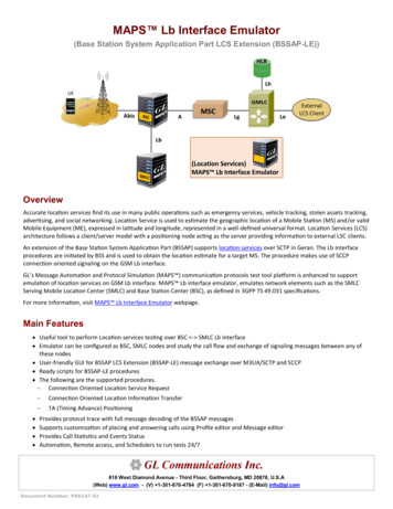
NE-ONE Network Emulator User and Administration Guide V4.14 Setting up a Point to Point EmulationPoint to Point is the emulation of one or more network links between twolocations or devices. In this example we will emulate a network link betweenNew York City and Philadelphia.To configure a Point to Point emulation, click on the ‘Point to Point (Single orMulti Link)’ button.Note: Most but not all Emulator models support multiple links, for single linkmodels ignore the reference to multiple links. A single link model cannotsupport Dual-Hop emulations.In this example we will be using the Emulator’s Port Pair 0&1.The Point to Point configuration screen is displayed.16
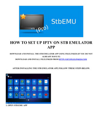
NE-ONE Network Emulator User and Administration Guide V4.1Note: In most of this guide we will only display the upper half or relevant partof the Emulation GUI.Configuring the End PointsNext, we need to configure the End Points (shown as Ethernet port icons withlabels “Not Configured Port 0” and “Not Configured Port 1” by default).This is achieved by clicking either Ethernet port icon.The END POINT PROPERTIES panel is displayed.You have two options for how you configure End Points:If you select (tick) the “Enable End Point Location Entry” then as you starttyping a list of countries andlocations within the country willappear that match your criteria.Select the country and the locationfrom the drop-down lists. Thelatency between the two end pointcities is automatically determined.If you deselect (untick) the “EnableEnd Point Location Entry” then thelatency value associated with thedistance between the two EndPoints must be entered manually.If you use the endpoint feature, then the base latencies are based on alandline connection between those locations. If you then tell it that thenetwork will be 3G (for example) then the landline values are modified to suitthis network.We can also change the icons using the “Change Icon” buttons to betterrepresent the purpose of the End Point e.g. a corporate HQ building.17
NE-ONE Network Emulator User and Administration Guide V4.1A user may wish to use his own icons and these can be added to the icondatabase. Click on the Browse button at the top of the end point icon dialog,browse to the image file and click Upload. This will be added to the list in theabove diagram and will remain unless selected and deleted by the user.Configure both End Points. You will now see that the End Points have beensuccessfully configured with the locations specified. The End Points arelooked up and a corresponding latency is determined. When you click OK, amessage pops up explaining extra latency of x ms has been added to theemulation as a result of configuring real locations.Note: Any changes in link quality “combo field” will provide additional delay(latency) which will be added to the location-based delay value and reflect inthe total value in the field as long as location entry is enabled. All these ONLYapply to basic mode.Configuring the Link(s)We now need to configure the Link or Links between the End Points.This is achieved by clicking on the relevant Link. It is normal and advisable,although not compulsory, to configure the Links in number order.When you configure a link, it is enabled (green in color) by default. If you don’twish to configure the link either cancel editing it or untick the Enable Link box.You can configure the link but not enable it if you want to enable it later, forexample.18
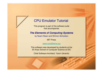
NE-ONE Network Emulator User and Administration Guide V4.1Note: Enabled is not the same as configured. A Link can be enabled,configured but not enabled or enabled and configured. The ability to disable aLink is provided for operational flexibility during emulation testing.The LINK PROPERTIES (for the relevant Link) panel is displayed in “Basicmode” (click on Advanced for Advanced Configuration Mode):Decide if you wish to enable the Link at this stage.You can also change the Link Name to something more appropriate, ifrequired.Then select the Link Type, Subtype and Link Quality that you require.The Bandwidth, Latency (if you enabled End Point locations in the End Pointconfiguration) and Loss (%) settings will be automatically completed for you.You can overwrite any of the impairment values individually, or, alternatively,you can select ”Custom” from the Link Type, and all the impairment fields willbe blank or zero to facilitate manual entry.Note: For certain network links it is common to have different Bandwidthvalues in the uplink and downlink directions. The Emulator defaults tosymmetric values, which may need to be changed manually.19
NE-ONE Network Emulator User and Administration Guide V4.1The link is now configured and ready for use.Repeat the Link configuration process, but NOT the End point configuration,for each Link that needs to be configured.Additional links can provide different network experiences for different IP’s,VLANs or TCP ports (see next section).To add a link, either click on the sign for the dotted link at the top or click onthe cog on the first link and select Duplicate Link (this will copy all the samevalues set for this link to a second link).Note: You can only add links up to the maximum number permitted by theemulator license.To edit a link, either click on the number of the link you wish to change, orclick on the cog and select Edit Link.It is also possible to delete a link by clicking on the cog and selecting deletefrom the menu.Link Qualification CriteriaWhen you configure multiple Links (multiple paths between the End Points) itis necessary to define criteria specifying what traffic travels over which Links(paths). If you don’t do this everything will go down the first configured andenabled link.The Link Qualification Criteria can also be used as a traffic filter i.e. if youselect a range of IP addresses for a particular link then only traffic associatedwith these source and destination IP addresses will traverse this link.Where no links exist to handle certain traffic, this traffic will be dropped by theEmulator.Specifying what traffic travels over which Link is handled in the LinkQualification Criteria Section in the Link Properties panel.20
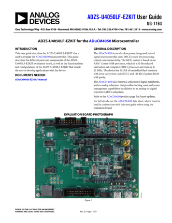
NE-ONE Network Emulator User and Administration Guide V4.1The Link Qualification Criteria allows you to select the IP addresses,TCP/UDP Ports and the VLAN tags that will be allowed to run over this Link.Refer to “Appendix A – Entering Data Values” for a detailed description of theinput options.There is also an Advanced Expressions box for entering criteria with morecomplex expressions e.g. ipv4.dst 192.168.100.1 ORipv4.src 192.168.100.1.In this box the user should enter an expression which describes (in Wiresharklike syntax) data that qualifies for this link. For example: eth.dst 00:1B:21:91:D8:F6 or eth.src 00:1B:21:91:D8:F6 - wouldselect that single mac address ipv4.proto 17- would select only UDP packets tcp.Destination Port 80 or tcp.source Port 80- would select onlyport 80 for TCP, not UDP ipv4.tos x0A - selects DSCP class AF11Notes: Link qualifications are in general symmetric so that both directions usethe same link, hence source and destination used in the examples above.These expressions are ANDed with any selections in the IP address, port orVLAN boxes.Refer to “Appendix C – Expressions” for more detail on Expressions.Mini-GraphsWhen an emulation is running in Standard Emulation mode, mini-graphs canbe displayed at either or both end points of the link, and pictorially indicatewhether packet traffic is flowing through that end point. To select one or bothmini-graphs, click on the cog-wheel on the Link between the two end pointsand select the appropriate graph to be displayed as shown in the nextdiagram:21
NE-ONE Network Emulator User and Administration Guide V4.1The diagram below shows mini-graphs displaying for both end points andshows the traffic activity through each end point:To dismiss a mini-graph click on the green ‘x’ in the top right-hand corner ofthe required mini-graph as shown in the next diagram:22
NE-ONE Network Emulator User and Administration Guide V4.1Advanced ModeOverviewThe Edit Link Properties dialog in Basic Mode allows the user to set up aconfiguration with Point to Point and Dual Hop configurations. Whilst BasicMode is extremely intuitive and quick to use there is also an Advanced Modefor the more experienced user that wants to setup more sophisticatedEmulation impairment configurations.It is sometimes expedient to start a configuration in Basic Mode and thenswitch to Advanced Mode. In this situation the following items would becarried across:Advanced ModeAuto-ConfigurationModeItemFunctionNotesLeft - RightBandwidthQueueLink speed andFIFO Queue Bytes-Right - LeftBandwidthQueueLink speed andFIFO Queue Bytes-Min and Max LatencyLatencyRandom DelayValues are copiedsymmetrically to Left - Rightand Right - Left.Loss (%)LossRandom DropValue is copiedsymmetrically to Left - Rightand Right - Left.In Advanced Mode the Edit Link Properties page appears as follows:23
NE-ONE Network Emulator User and Administration Guide V4.1There are two lines of tabs – the top line allows the user to configure theproperties for the link direction for Port 0 to Port 1, Port 1 to Port 0 and theLink Qualification Criteria. The second line of tabs allows the user to configurevarious categories of impairments: Bandwidth (including Congestion) Latency Loss Duplicate Out of Order Fragment Bit ErrorIf a tab has a tick by it then that category of impairment is enabled. Theunticked tabs mean those impairments have not been enabled. With eachcategory of impairment, the user may be offered one or more methods ofimpairment for that category, e.g. For Latency, there are seven methods asfollows:24
NE-ONE Network Emulator User and Administration Guide V4.1In this case the Random Delay method is selected (which is the same as theBasic Mode latency method of impairment). Once the impairments requiredhave been set, press the Ok button at the top to set and return to the Setup &Control page.Note: Each impairment method has its own specific set of parametersdisplayed to the right of the list of methodsLink Routing (Link Qualification Criteria)As with Basic Mode when you configure multiple Links (multiple pathsbetween the End Points) it is necessary to define criteria specifying whattraffic travels over which Links (paths). If you do not define this everything willgo down the first configured and enabled link.Replacing Emulation with Similar EmulationWhen configuring an emulation, or having loaded a particular emulation file,the user can replace it with a “similar” emulation file. By clicking on the “LoadSimilar” button the user is presented with a list of emulation files that contain astructurally similar configuration i.e. if the current emulation only has one linkthen the list of “similar” emulations will also only have one configured link(even if it is disabled). Equally, if the current emulation has two links, the list of“similar” emulations will also only have two links even if one or both links aredisabled etc.25
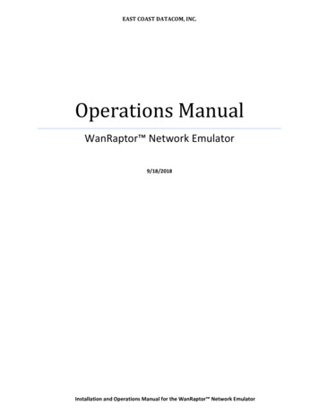
NE-ONE Network Emulator User and Administration Guide V4.1Starting the EmulationTo start the emulation, click on the “Start” button above the EmulationConfiguration display on the Setup & Control page.In the example above if we connected a PC to Port 0 (New York City) andpinged a Server connected to Port 1 (Philadelphia) we would observe thelatency of approximately 12 ms. This is the round-trip latency – the end pointlocation added 3 ms to the link quality. For a WAN type OC3 network ofexcellent quality, the latency would be 3 ms, giving a combined total of 6 msbetween cities. Therefore, pinging one end point to the other produces around trip latency of 12 ms.When the “Start” button is clicked, the emulation starts execution, the “Start”button is greyed out, and the “Stop” and “Update” buttons become active. The“Load Similar” button also changes to “Load & Update”.26
NE-ONE Network Emulator User and Administration Guide V4.1Whilst an emulation is running it is possible to load a structurally “similar”emulation and for it to automatically adjust the parameters to the newemulation, continuing running from where the previous emulation was running,without stopping and starting the emulation itself. The structure of the twoemulations MUST be the same in order to do this i.e., both emulations musthave a matching number of end points and links, even if one or more of thelinks in the current or new emulation are disabled. A single or two-linkemulation can only be replaced by a single or two-link emulation, respectively.If a two-link emulation is running and the second emulation also has two linksbut one of them disabled, it is still possible to replace the first emulation withthe second emulation. A single link emulation cannot be replaced with anotherthat has two or more links, even if they are all bar one disabled. And viceversa, a multiple link emulation (through link qualification criteria) cannot bereplaced by a single link emulation file.Click on the “Load & Update” button, and a dialog pops up with a list of“similar” emulation files. Select a new emulation file and click “Update” or“Update & Close”. If “Update” is selected the dialog remains on display andthe list of emulation files is refreshed, removing the current running emulationand adding the previous emulation file. If “Update & Close” is selected thedialog closes having updated the running emulation.Saving the ConfigurationIf you wish to save the configuration, click on the “Save As” button at the topof the Setup & Control page.27
NE-ONE Network Emulator User and Administration Guide V4.1Enter an Emulation Name and a description of this emulation, if required.Click “Save As” to store on the Appliance.Saved emulations can be run from the LCD panel (see the LCD Panel UserGuide for more information).28
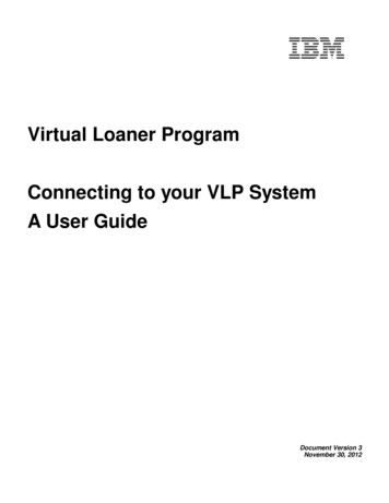
NE-ONE Network Emulator User and Administration Guide V4.15 Setting up a Dual-Hop EmulationA Dual-Hop emulation is still a Point to Point emulation but it supports amiddle hop (which could be another location) or a Last Mile emulation at oneof the End Point locations. In this regard we can think of Dual Hop Emulationsas Multi-Link emulations. In this example we will emulate a network linkbetween New York City and Philadelphia.To configure a Dual-Hop emulation, click on the “Dual-Hop (Single or DualLink)”.Note: Most but not all Emulator models support Multiple links. A single linkmodel cannot support Dual-Hop emulations.In this example we will be using the Emulator’s Port Pair 0&1.The Dual-Hop (Single or Dual Links) configuration screen is displayed.29
NE-ONE Network Emulator User and Administration Guide V4.1Configuring the End PointsFirst, we need to configure the End Points (shown with the labels “NotConfigured Port 0” and “Not Configured Port 1” by default).However, with Dual-Hop emulations there is also a Middle (End) Point (shownas a Router icon default).Configure the End and Middle PointsConfiguring the End Point properties is achieved by clicking either Ethernetport icon.The END POINT PROPERTIES panel is displayed.You have two options for how you configure End Points:If you select (tick) the “Enable End Point Location Entry” then as you starttyping a list of countries and locations within the country will appear thatmatch your criteria. Select the country and the location from the drop-downlists. When you click OK, the latencies between the end point locations will beautomatically determined and added to the link. In this case it will add a linkquality base latency of 3ms and 2ms.If you deselect (untick) the “Enable End Point Location Entry” then the latencyvalue associated with the distance between the two End Points must beentered manually.30
NE-ONE Network Emulator User and Administration Guide V4.1We can also change the icons using the “Change Icon” buttons, to reflect thenature of the End Point.A user may wish to use his own icons and these can be added to the icondatabase. Click on the Browse button at the top of the end point icon dialog,browse to the image file and click Upload. This will be added to t
NE-ONE Network Emulator User and Administration Guide V4.1 6 1 Introduction The NE-ONE Network Emulator is a sophisticated but easy to use product featuring a highly intuitive pictorial web GUI with a unique self-configuration capability. All NE-ONE models, except the NE-ONE Flex Model 1, support multiple links and Dual-Hop/Last Mile capability.