Transcription
Netropy Network Emulator User’s GuideRevision 3c, August 2017Apposite Technologies LLC17835 Ventura Blvd., Suite 211Los Angeles, CA 91316 e-tech.comCopyright 2005-2018 Apposite Technologies LLC. All rights reserved. Apposite, Linktropy, and Netropy areregistered trademarks of Apposite Technologies LLC. The Apposite logo and “WAN Emulation Made Easy” aretrademarks of Apposite Technologies LLC. Android and the Google Play logo are trademarks of Google Inc.Part No. DOC-UG-NNE-3c
CONTENTS1 Overview . 51.1 Netropy Configuration . 51.2 Netropy Operation . 51.3 Netropy Models and Firmware Versions . 62 Installation and Set-Up . 72.1 Preparation . 72.2 Hardware Installation . 72.3 IP Address Configuration via the Netropy GUI . 82.4 IP Address Configuration via the Serial Console . 82.5 Network Installation . 93 Configuration .103.1 Emulation Engine .103.2 Paths .113.3 Classifiers .113.4 GUI and CLI .114 Emulation Engine .124.1 Overview of Emulation Engines .124.2 Engine Locking .144.3 Engine Self-Monitoring .145 Paths .155.1 Overview of Paths .155.2 Single-Link and Per-Client Emulation Paths .165.2.1 Single-Link Mode .165.2.2 Per-Client Emulation Mode .165.3 Path Types .175.4 Configuring Paths .185.5 Adding and Deleting Paths .186 Path Parameters: Configuring Emulation Conditions .19
6.1 Configuring Path Parameters .196.2 WAN Access Parameters .206.2.1 Link Type .216.2.2 Bandwidth .216.2.3 Background Utilization .226.2.3.1 Random Background Traffic . 226.2.3.2 Packet Replay Using PCAP Files . 236.2.4 Queue Limit .256.2.5 Queuing Strategy .266.2.6 MTU Limit .276.2.7 Frame Overhead .286.3 WAN Parameters .296.3.1 Delay .306.3.2 Loss .326.3.3 Network Outage .336.3.4 Corruption .346.3.5 Reordering .346.3.6 Duplication.357 Packet Classifiers .367.1 Overview of Packet Classification .367.2 Classification Methods .377.2.1 Classification Off .387.2.2 IP Address Classification .387.2.3 IPv6 Address Classification .397.2.4 VLAN Classification.407.2.5 MPLS Label Classification .417.2.6 MAC Address Classification .427.2.7 TCP/UDP Port Classification .437.2.8 Combination Classification .457.3 Rule Order .488 Recordings .498.1 Overview of Recordings .498.2 Managing Recordings .508.3 Recording Playback .51
8.4 Recording File Format .538.5 Example Recording File .549 Monitoring & Statistics Download.559.1 Graphs.559.2 Statistics .569.2.1 Statistics Download .5810 Administration .6010.1 Network Settings .6010.2 Users .6110.3 Bridge/Route .6210.3.1 Bridging .6210.3.2 Routing .6310.4 Ethernet Settings .6410.5 Recordings .6510.6 Packet Captures.6510.7 Save and Restore Engine Configurations .6510.8 Management Network Status .6610.9 Engine Log .6610.10 Firmware .6710.11 License Key .6810.12 Date and Time .6811 Command Line Interface .6911.1 CLI Help .6911.2 Navigation within the CLI .7011.3 CLI Top Level Commands .7111.3.1 LDAP Management Commands .7511.3.2 Capture Command .7611.4 CLI Engine Mode Commands .7711.5 CLI Path Mode Commands .7911.5.1 CLI Set Emulation Parameters .8012 Security .8512.1 Users and Passwords .8512.2 Engine Locking .8512.3 Recovering from a Lost Admin Password .8512.4 SSL.86
12.5 SSH .8612.6 LDAP .8613 Apposite Support .8813.1 Registration .8813.2 Customer Support .88Appendix A: Apposite End User License Agreement .90Appendix B: Third Party Licenses .93
OVERVIEWThank you for purchasing the Apposite Technologies Netropy network emulator. This User’sGuide describes the installation, configuration, and operation of the Netropy product. Acompanion Hardware Guide describes the Netropy hardware for each specific model. A separateQuick Start Guide provides a walk-through for first time configuration.The Netropy network emulator attaches to an Ethernet network and simulates the bandwidth,delay, loss and other conditions of the wide-area network to test application performance.1.1 Netropy ConfigurationThe Netropy network emulator is usually configured through the browser-based Netropy GUI(Graphical User Interface). The GUI is accessible through a dedicated management port fromany PC or other device with a standard web browser using HTTP or HTTPS.In addition to the GUI, the Netropy network emulator includes a command line interface (CLI)that can be accessed via a serial console port or over the network using Telnet or SSH. The CLIcan be used to set the IP address of the management interface if the GUI is not accessible overthe network, and to modify emulated link conditions for integration with scripting and testautomation tools.1.2 Netropy OperationConfiguration and operation of the Netropy network emulator via the browser-based GUIrequires only a few simple steps:1. Open the GUIConnect to the Netropy unit through the dedicated management port using a standard webbrowser.2. Select the Emulation EngineDepending on hardware model, the Netropy unit will include between one and four separateEmulation Engines. Each Emulation Engine acts as an independent network emulationsystem connecting a pair of Ethernet ports.Section 1 Overview5
3. Add PathsCreate separate WAN paths to carry packets between the two Ethernet ports in each Engine.Each Emulation Engine can simulate up to 15 separate paths.4. Configure WAN conditions for each pathConfigure each path with the bandwidth, delay, loss, and other WAN conditions.5. Classify PacketsAssign packets to the paths by IP source and destination address range, VLAN, MACaddress, TCP/UDP port numbers, MPLS label, or other packet identifier.6. Start the Emulation EngineTurn on emulation to begin testing.7. Monitor trafficView the graphs and link statistics to monitor application performance.8. Change configurationThe configuration can be changed on the fly by adding or deleting paths, modifying pathconditions, or updating the packet classification rules.1.3 Netropy Models and Firmware VersionsThe six current Netropy models, N61, N91, 10G1, 10G2, 10G4 and 40G, can all run the firmwaredescribed in this User’s Guide. The various models offer identical functionality and differ only incapacity and number and type of network interfaces. The Netropy N90 model has beensuperseded by the N91 but can run the firmware described in this manual. Earlier Netropymodels, the N60, N80, and 10G, are limited to running firmware versions up to v2.2.Depending on when the Netropy unit was produced and if the firmware on the unit was updated,the unit may be running an earlier version of the firmware than described in this User’s Guide.Please consult the appropriate User’s Guide for the version of firmware running on your unit.Section 1 Overview6
INSTALLATION AND SET-UPTo configure and operate the Netropy network emulator through its browser-based GUI, thededicated Ethernet management port must first be configured with an appropriate IP addressand subnet mask. For convenience, the MGMT interface comes pre-configured with an IPaddress of 10.0.0.10, and is accessible from a directly-connected host on the 10.0.0.0/255.0.0.0subnet. The IP address and subnet mask of the MGMT interface can be changed through theNetropy GUI or through the command-line interface.2.1 PreparationManagement of the Netropy device through the GUI requires a PC running a web browser withFlash version 10 or later installed.Initial configuration of the management interface requires either: a PC running a supported web browser that can be configured and placed on the10.0.0.0/255.0.0.0 network. a PC with an RS-232 serial port running terminal emulation software such as HyperTerminalor PuTTY.2.2 Hardware InstallationPlug in a standard power cord (a U.S. power cord is supplied with the unit) and turn on thepower. Depending on the particular model, the system will be available for use within 1 to 4minutes.For additional hardware installation details, please see the Hardware Guide for your model.Section 2 Installation and Set-Up7
2.3 IP Address Configuration via the Netropy GUITo configure the MGMT interface using the Netropy GUI: Configure a PC running a supported web browser with the IP address 10.0.0.2 or otheraddress on the 10.0.0.0/255.0.0.0 subnet. Connect an Ethernet cable between the PC and the MGMT port on the Netropy unit. Open the browser on the PC and enter http://10.0.0.10. Review the End User LicenseAgreement. Netropy units are shipped with a temporary license pre-installed for initial operation.Follow the instructions on the screen to download and install a regular license. This stepmay be skipped, and the license installed later. Click on the Administration link at the top of the page and select the Network Settings tab.Set the IP address, subnet mask, and optional default gateway for the managementinterface, then click the Apply Changes button. After the management interface has been configured, use the Ethernet cable to connectthe MGMT port to the management network.2.4 IP Address Configuration via the Serial ConsoleTo configure the MGMT interface using the serial console: Using the provided serial cable, connect the serial port of a PC running terminal emulationsoftware to the CONSOLE port of the Netropy WAN emulator. Set the serial portparameters to 9600 baud, 8 bits, no parity, 1 stop bit, and disable flow control. See theHardware Guide for your model for more details on connecting to the serial console. Press [ENTER] to display a login prompt. At the prompt, log in as “admin”. There is initiallyno password.netropy login: admin Use the following commands to set the IP address, netmask, and default gateway of theMGMT port:mgmt set addr ip-address netmask mask mgmt set gw default-gateway IP addresses and subnet masks are entered in dotted-decimal format. For example:Section 2 Installation and Set-Up8
[netropy] mgmt set addr 192.168.1.1 netmask 255.255.255.0 After the management interface has been configured, use an Ethernet cable to connectthe MGMT port to the management network. Open a browser and enter the IP address ofthe MGMT port. Review the Netropy End User License Agreement. Netropy units are shipped with a temporary license pre-installed for initial operation.Follow the instructions on the screen to download and install a regular license. This stepmay be skipped and the license installed later.2.5 Network InstallationEach Netropy Emulation Engine is installed between two LAN segments and acts as a bridge orrouter between those two segments. Packets received on one port of the Emulation Engine aresubjected to configured emulation conditions before being forwarded or routed to the oppositeport.If configured as a layer 2 bridge, install each Engine on an Ethernet network in a location wherethe traffic that is to be sent over the emulated WAN will be forced to flow through the device. Ifconfigured as a router, install the Engine between two separate subnets and configure staticroutes to pass traffic through the Engine. Each Engine is configured separately as a bridge orrouter.Section 2 Installation and Set-Up9
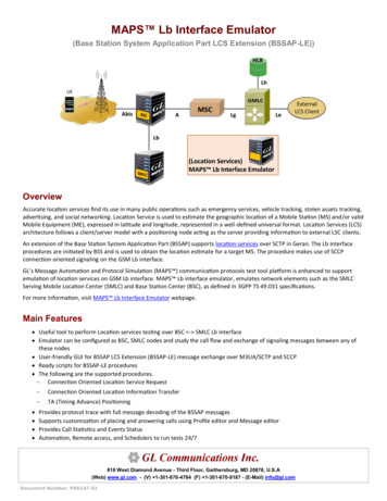
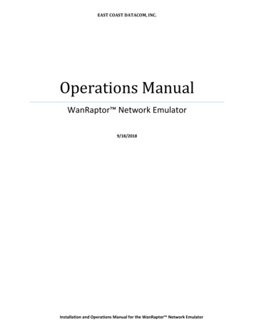
CONFIGURATIONConfiguration of the Netropy network emulator is aided by understanding a few basic conceptsand terminology.3.1 Emulation EngineThe Netropy Emulation Engine forwards packets and applies the configured emulationconditions between a pair of Ethernet ports.Figure 1: Two separate Emulation Engines,each with 15 paths between each pair of ports.Depending on hardware model, the Netropy unit contains between one and four separateEmulation Engines. Each Engine operates independently of the others, and can be thought of asa separate emulation device. Each engine has its own Ethernet ports, a network architecturethat may include multiple paths and classifiers, and separate traffic statistics and graphs.See Section 4 for more details on the Emulation Engine.Section 3 Configuration10
3.2 PathsA path is a single configuration of bandwidth, latency, loss, and other network properties. EachEmulation Engine can have up to 15 separate paths.In the default single-link mode, each path represents a single WAN link, and all traffic using thepath is aggregated over the path. In per-client emulation mode, each path represents one set ofemulation parameters, but the traffic to and from each separate IP address is allocated its ownseparate bandwidth.Each path consists of three components: a WAN access link connecting the LAN to the WAN oneach side and traversal over the WAN in the middle.Each WAN access link connects a LAN to the WAN. Bandwidth constraints and conditions thataffect bandwidth availability are configured in the WAN access link. The traversal over the WANis characterized primarily by its latency, jitter, and loss conditions.See Section 5 for more details on configuring paths.3.3 ClassifiersClassifiers are sets of rules or filters that specify which packets are sent over which paths. Eachport has its own classifier to direct the packets that arrive on that port. Most users will classifypackets by IP source and destination address range, but packets can instead be classified byIPv6 address, VLAN, MPLS label, MAC address, TCP or UDP port number, or any other packetfield or combination. Each classification rule includes an action that specifies whethermatching packets are sent over one of the configured paths, dropped, or forwarded withoutemulation.See Section 7 for more details on configuring classifiers.3.4 GUI and CLIMost users will find the browser-based graphical user interface to be the most convenient wayto configure and operate the Netropy network emulator. However, a CLI is also available forintegration with test automation tools.The device can be managed and any of the path emulation parameters can be set and modifiedthrough the CLI. However, the configuration of the emulated WAN architecture, includingcreating paths and building classification rules, must first be completed through the GUI.See Section 11 for more details on the CLI.Section 3 Configuration11
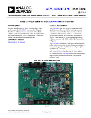
EMULATION ENGINE4.1 Overview of Emulation EnginesThe Netropy Emulation Engine forwards packets and applies the configured emulationconditions between a pair of Ethernet ports.Depending on hardware model, the Netropy unit contains between one and four separateEmulation Engines. Each engine operates independently of the others, and can be thought of asa completely separate emulation device. Each engine has its own Ethernet ports, a networkarchitecture that may include multiple paths and classifiers, and separate traffic statistics andgraphs.To configure a particular Emulation Engine from the Netropy GUI, click on the correspondingEngine button at the top of the main page.Each Emulation Engine can be turned on or off independently. Emulation is initially turned off onall engines after reboot or power cycle. Emulation can be turned on or off from the main page ofthe GUI or through the CLI. When emulation is off, all packets are forwarded directly between theEmulation Engine’s two ports, bypassing any emulation.Throughput graphs and statistics can be viewed for emulated paths, as well as for the bypasstraffic.The entire configuration of any Emulation Engine can be downloaded to a local file from theSave tab of the Administration window. This configuration file can then be used to reconfigureany Engine.Section 4 Emulation Engine12
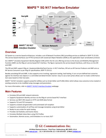
Figure 2: Main Page of the GUISection 4 Emulation Engine13
4.2 Engine LockingUsers can lock individual Emulation Engines to prevent any changes made to the configurationby other users. Only the user who locked the engine and the admin user can modify theconfiguration of a locked engine or unlock the engine. Locking is specific to each individualengine. Different users can lock different engines, or a single user can lock multiple engines.To lock an Emulation Engine, click thelock icon. To unlock, click again.For details on creating and administering users, see Section 10.2.4.3 Engine Self-MonitoringThe Netropy Emulation Engine performs continuous self-monitoring to ensure that test resultshave not been affected by limitations on the processing or buffering resources of the Netropyengine.The current status of the Netropy engine is indicated by the LEDs on each engine selectionbutton. The LED on the left shows engine processing resources and the LED on the right showsengine buffering resources. Resource availability is indicated by the LED color:Green: Engine is functioning normally with sufficient resources for the current processing andbuffering load.Yellow: Resources are running low. Engine is functioning without error and tests are valid, but ifprocessing or buffering load increases further, the engine is in danger of reaching overloadconditions.Red: Overload fault. Sufficient processing or buffering resources were not available and testresults may have been affected. If a fault occurs, please review the error message in the log.If an overload of processing or buffering occurs, the LEDs will remain red to indicate an erroruntil the log message has been marked as read or the log has been cleared.Hovering over the engine button displays a tool tip with details of the current status.Section 4 Emulation Engine14
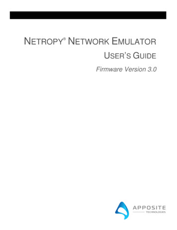
PATHS5.1 Overview of PathsA path is a single configuration of bandwidth, latency, loss, and other network properties. EachEmulation Engine can have up to 15 separate paths. In the default single-link mode, each pathrepresents a single WAN link, and all traffic using the path is aggregated over the path. If perclient emulation mode is enabled, each path represents one set of emulation parameters, butthe traffic to and from each separate IP address uses a separate WAN access link with separatebandwidth.
The Netropy network emulator attaches to an Ethernet network and simulates the bandwidth, delay, loss and other conditions of the wide-area network to test application performance. 1.1 Netropy Configuration The Netropy network emulator is usually configured through the browser-based Netropy GUI (Graphical User Interface).