Transcription
MSP430 JTAG / BSL connectors(PD010A05 Rev-4: 23-Nov-2007)FAQ:Q: I have a board with the standard TI-JTAG pinhead. Can I use your programmer to flash myMSP430Fxx device?A: Yes. You can use any of our programmers to flash your device via standard 14-pin TI-JTAGconnector. Our programmers use 14-pin connectors with the STANDARD TI-JTAG pinhead.In addition you can use the same connector to facilitate communication via BSL interface.Q: How can I connect the Fast MSP430 JTAG/BSL Flash Programmer to the BSL (Bootstrap)interface.A: We have two programmer models with the standard BSL pinhead connector (10-pins). Youcan use one of these programmers to communicate with the BSL interface. Our 14-pins JTAGconnectors also support the BSL communication.Q: How can I use the BSL interface on the Texas Instruments evaluation board with your FlashProgrammers when only one 14-pin cable is provided?A: Our Flash Programmers can utilize the 14-pin connector to facilitate both JTAG and BSLcommunication. To enable the BSL communication on the Texas Instruments evaluation boardvia the JTAG connector make the following wire connections on the evaluation board:BSL pin-1BSL pin-3totoJTAG pin-12JTAG pin-14- (BSL-Tx)- (BSL-Rx)This modification DOES NOT affect the JTAG adapter, as the pins assigned to the BSL-Tx andBSL-Rx signals are unused by the JTAG Interface. This modification will allow you tocommunicate via JTAG or BSL interface using a single JTAG connector. Also you can still useany adapter with the standard BSL or JTAG pinhead cable using the:1. BSL connector with the standard TI-BSL pinhead cable2. JTAG connector with the standard TI-JTAG pinhead cable3. JTAG connector with the Elprotronic’s JTAG/BSL pinhead cable.MSP430 JTAG / BSL connectors. PD010A05 Rev-4: 23-Nov-2007Copyright Elprotronic Inc.www.elprotronic.comPage 1
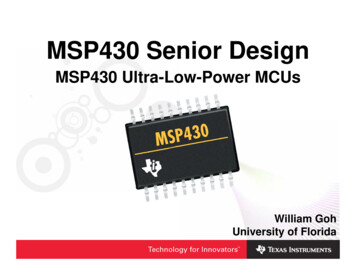
Joint JTAG and BSL connectorThe Fast MSP430 Flash Programmers (USB and Parallel Port versions) with the JTAG andthe BSL Interfaces use the STANDARD 14-pin TI-JTAG connector’s pinout to facilitate theJTAG communication. Some of the unused pins on this connector are utilized to facilitate BootstrapLoader (BSL) communication.Texas Instruments created the standard for the MSP430 JTAG interface connector and forthe Bootstrap Loader (BSL) connector. The JTAG and the BSL connectors share several commonsignals, such as RST, GND, Vcc, Vcc-Out, TEST and TCK. The BSL connector uses signals BSLTx and BSL-Rx that are not found in the JTAG connector. We can notice that the TI-JTAGconnector has specified a maximum of 11 pins, and the remaining 3 pins are not used. These threepins can be used for the two BSL signals, namely BSL-Tx and BSL-Rx. By utilizing these unusedpins enables us to facilitate both the JTAG and the BSL communication interfaces on a SINGLE14-pin JTAG connector.This modification DOES NOT affect the JTAG adapter, as the pins assigned to the BSL-Txand BSL-Rx signals are unused by the JTAG Interface. This can save one connector and can simplifycommunication with the target device.The pinout for the standard JTAG connector with added BSL-Tx and BSL-Rx signals isshown in figure 1. BSL-Tx and BSL-Rx signals are connected to the pins 12 and 14 respectively. Inaddition, a ground line is connected to pin 13. The JTAG signal lines are connected to pins number1 through 11 in compliance with the standard JTAG specification provided by Texas Instruments.The definition of all pins is given in the table 1.MSP430 JTAG / BSL connectors. PD010A05 Rev-4: 23-Nov-2007Copyright Elprotronic Inc.www.elprotronic.comPage 2
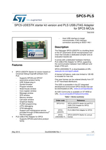
Stand-alone BSL connectorFigure 2 shows the standard BSL connector signals for the programming adapter. The definition ofall pins is given in the table 2.Figure 2. BSL header connector solder side.Table 1 JTAG Interface connectorPin #NameDescription1 (Red)TDO/TDIData output2Vcc/ SenseVcc supplied to the Target Device and Target’s Device Vcc Sense3TDI-VppData Input - Blow Fuse voltage Vpp ( 6.5V)4SenseTarget’s Device Vcc Sense( used in the USB-MSP430-FPA - rev.1.1 and up andin the Parallel Port version programmer - PE010X01- 04 )( not used in the USB-MSP430-FPA rev.1.0, PE010X01- 01, -02, -03 )5TMS-InTMS Input6NCNot connected7TCK-InBootloader / JTAG TCK Input pin8TEST-VppBootloader / JTAG TEST Input pin, Blow Fuse voltage Vpp ( 6.5V) (note-4)9GNDGround10NCNot connected11\RSTMicrocontroller Reset Input pin.12BLTx-Out (*)Bootloader Tx Output from the target (note-1)13GND(*)Ground14BLRx-In(*)Bootloader Rx Input to the target(note-3)(note-2)MSP430 JTAG / BSL connectors. PD010A05 Rev-4: 23-Nov-2007Copyright Elprotronic Inc.www.elprotronic.comPage 3
Table 2 BSL Interface connectorPin #NameDescription1 (Red)BLTX-OutBootloader Tx Output from the target (note-1)2TCK-InBootloader / JTAG TCK Input pin(note-3)3BLRx-InBootloader Rx Input to the target(note-2)4\RSTMicrocontroller Reset Input pin.5GNDGround6VCC/ SenseVcc supplied to the target and Target’s Device Vcc Sense7TEST-InBootloader / JTAG TEST Input pin8SenseVcc Output (max 6V) or Power Off signal from the target. (note-5)9ncNot connected10ncNot connectedNOTE (*):Note-1.Note-2Note-3Note-4Note-5(note-4)Pins numbers 12,13 and 14 of the JTAG connector has modified connectioncompared to the standard TI JTAG FET adapter. Typically those pins are not usedin TI JTAG FET but has been used in the Fast MSP430 Programming adapter topass the Tx and Rx signals of the BSL communication port. When this modificationis done, then one modified 14-pins JTAG connector can be used to JTAG and BSLcommunication between target device and programming adapter.BLTX-Output - Transmit data output pin from the bootstrap loader.Port pin 1.1 for microcontrollers MSP430F1xx.Port pin 1.0 for microcontrollers MSP430F4xx.BLRx-Input - Receive data input pin to the bootstrap loader.Port pin 2.2 for microcontrollers MSP430F1xx.Port pin 1.1 for microcontrollers MSP430F4xx.TCK-Input - for BSL used only for microcontrollers with package over 28 pins.TEST-Input - for BSL used only for microcontrollers with package up to 28 pins.Signal is not mandatory. Can be connected to external power supply with DC voltagebetween 5V to 6V to power the target devices via adapter’s LDO 3.3V regulator andcontrolled by interface switch (see block diagram). Maximum current supplyingtarget devices in this case can not exceed 200 mA (instead of 15 mA without externalpower supply).Refer to the Texas Instruments data sheet for detailed information related to pin numberingof a particular microcontroller.MSP430 JTAG / BSL connectors. PD010A05 Rev-4: 23-Nov-2007Copyright Elprotronic Inc.www.elprotronic.comPage 4
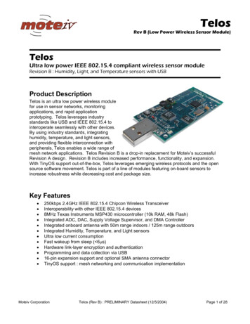
Example how to provide the JTAG / BSL connectionFigure 3 show typical interconnection between the JTAG (14 pin header connector), theBSL connector (10 pin header connector) and MSP430F149 microcontroller.Figure 4 show interconnection between modified JTAG connector and MSP430F149microcontroller. Two lines - BLRx and BLTx have been connected to not used pins 12 and 14 of thestandard JTAG connector. This modification allows use of the only one modified JTAG connectorto connect the JTAG and BSL communication interface to programming adapter.Figure 5 show interconnection with MSP430F1122 microcontroller.Figure 3MSP430 JTAG / BSL connectors. PD010A05 Rev-4: 23-Nov-2007Copyright Elprotronic Inc.www.elprotronic.comPage 5
Figure 4Figure 5MSP430 JTAG / BSL connectors. PD010A05 Rev-4: 23-Nov-2007Copyright Elprotronic Inc.www.elprotronic.comPage 6
Figure 6 show interconnection between JTAG/SBW connector and the MSP430F2031microcontroller using the Spy-Bi-Wire interface.Figure 7 and 8 shows Spy-Bi-Wire and RESET circuits.Figure 9 to 12 shows interconnection between JTAG/SBW/BSL connector and theMSP430F22x4 microcontroller using the BSL only, Spy-Bi-Wire and BSL and JTAG and BSLinterfaces (without RESET circuits).Refer to the Texas Instruments data sheet for detailed information related to pin numberingof a particular microcontroller.Due to high communication speed (up to 4Mbit/s) via JTAG interface, the JTAG linesshould be connected directly from the connector to the target device. PCB lines should be as shortas possible. Total cables and PCB lines length from the JTAG programming adapter to the JTAGtarget device pins (ribbon cable, connectors and traces on the PCB) should not exceed 50 cm ( 20inches ) to avoid communication problem. If from any reason the target device contains extracomponents like capacitors or suppressors in the JTAG lines then the slower JTAG communicationspeed can be selected. The FlashPro430 software allows to select 4Mb/s, 1Mb/s and 400 kb/sJTAG communication speed between programming adapter and target device (software version 1.08and higher).Figure 6MSP430 JTAG / BSL connectors. PD010A05 Rev-4: 23-Nov-2007Copyright Elprotronic Inc.www.elprotronic.comPage 7
Figure 7Figure 8MSP430 JTAG / BSL connectors. PD010A05 Rev-4: 23-Nov-2007Copyright Elprotronic Inc.www.elprotronic.comPage 8
Figure 9Figure 10MSP430 JTAG / BSL connectors. PD010A05 Rev-4: 23-Nov-2007Copyright Elprotronic Inc.www.elprotronic.comPage 9
Figure 11Figure 12MSP430 JTAG / BSL connectors. PD010A05 Rev-4: 23-Nov-2007Copyright Elprotronic Inc.www.elprotronic.comPage 10
Q: How can I connect the Fast MSP430 JTAG/BSL Flash Programmer to the BSL (Bootstrap) interface. A: We have two programmer models with the standard BSL pinhead connector (10-pins). You can use one of these programmers to communicate with the BSL interface. Our 14-pins JTAG connectors also support the BSL communication.