Transcription
TH EWO R L DMSP430 Ultra-Low-PowerMicrocontrollersThird Quarter 2000LE A D E RI ND S PA N DAN A L O G
Key BenefitsMSP430 Microcontrollers—TheSolution for Battery-PoweredMeasurement Lowest system power extendsbattery life Integrated analog data conversionaccelerates time to market Communications peripherals enableeasy connectivity Pricing starting at 0.99 eachThe increasing demand tointegrate features and processingcapabilities into battery poweredproducts has created a need formicrocontrollers that are bothpowerful and highly integrated,while only requiring minuteamounts of energy to operate.Using its leadership in bothmixed-signal and digital technologies, Texas Instruments (TI) hasmet this challenge. The resultis the MSP430 line of ultra-lowpower microcontrollers, whichenables system designers tosimultaneously interface to analogsignals, sensors, and digitalcomponents while maintainingunmatched ultra-low-powerperformance.The MSP430 achieves its highperformance through a revolutionary architecture that integrates apowerful 16-bit RISC CPU for fastexecution of code and a designthat makes extensive use of standby modes to minimize currentconsumption when the CPU is notactive. The MSP430 architectureincludes an array of powerful andhighly flexible peripherals that arealso optimized for ultra-low-poweroperation.A key to the MSP430 performance is its unique ultra-lowpower modes. The MSP430 is ableto switch from ultra-low-powerstandby mode, where it onlydraws 0.8 µA of current, to fullcombination of features. Forapplications such as, security systems, utility metering, portablemedical devices and handheldinstrumentation, the MSP430 lineof ultra-low-power microcontrollers offer solutions that enableproduct ideas to become reality.active mode in a maximum of6 µs. This ultra-fast start upallows the MSP430 to stay instandby mode longer, eliminatingthe unnecessary current othermicrocontrollers use in rampingto active mode. In addition, whilein active mode, the MSP430 onlyrequires 250 µA in a typical 3 Vsystem. The time the MSP430stays in active mode is minimizedby its powerful 16-bit CPU, whichensures high speed and efficientcode execution.All MSP430’s peripherals areable to run independently of theCPU. This allows them to remainactive even while in ultra-lowpower standby mode. For example, an external 32 kHz crystalcan increment a counter for areal-time clock function, whilethe part is drawing just 0.8 µA.The MSP430 can also maintain anLCD display and await externalkey switch interrupts while instandby mode. This allows theuser interface to be fully activewhile simultaneously maximizingthe battery life. The MSP430 iseven capable of accepting external interrupts while it is in RAMretention/off mode. While in offmode, the MSP430 requires amere 0.1 µA of current.When battery life, processingpower and hardware flexibilityare major design concerns, TI’sMSP430 offers an unbeatable2MSP430 16-Bit RISC CPUThe MSP430’s powerful 16-bitRISC core offers many advantages over competing 4- and 8-bitmicrocontrollers. The MSP430CPU features the ease of use ofa RISC instruction set and theflexibility of numerous 16-bitCPU registers. These and otherfeatures result in a revolutionaryarchitecture that is highlyorthogonal by design.The MSP430 has a RISCinstruction set that consists of amere 27 core instructions, and tofacilitate more intuitive programming, 24 additional emulatedinstructions are included to further simplify the code generationprocess. For example, a commoninstruction such as enable interrupts (EINT) is included in theinstruction set. The assemblerautomatically substitutes theemulated instruction with thecorrect RISC instruction (BIS #8,SR). This combination of RISCand emulated instructions minimizes code space while also simplifying programming.
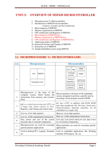
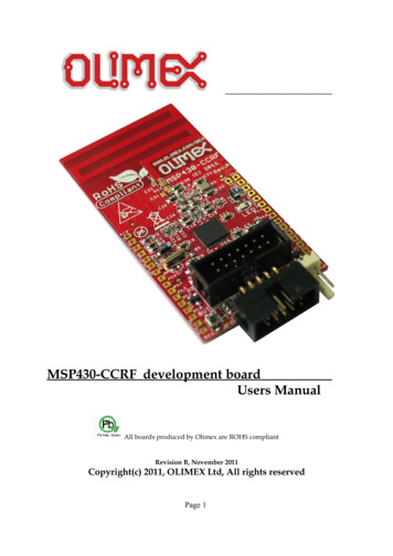
All instructions can be usedwith all seven addressing modesacross the entire MSP430 architecture. There are no specialinstructions or modes required towork with RAM, peripherals, theCPU, registers or any other partof the MSP430. This featuregreatly increases the efficiency ofthe 16-bit RISC instruction setand forms the basis for theorthogonal design of the MSP430.There are 16 registers in theCPU core of the MSP430. Four ofthe registers have the dedicatedfunctions of Program Counter(PC), Status Register (SR), StackPointer (SP) and ConstantGenerator (CG). The remaining12, 16-bit registers, are completely user definable.These generalpurpose registers in the CPUallow often-used variables,pointers and other data to bedirectly accessed by the CPUwithout performing memoryfetches. The number and flexibility of the CPU registers furthercontributes to the high code efficiency of the MSP430.Simplified MSP430 CPUMDB - memory data busmemory address bus - MAB150R0/PC - Program Counter0R2/SR - Status RegV SCG1 SCG0OscOffCPUOff GIE NZCR3/CG - Constant ISC ALU Shifter16MSP430 Orthogonal ArchitectureNon-Orthogonal ArchitectureAddress Modes SourceAddressModesDestination0R1/SP - Stack PointerAddress Modes ions
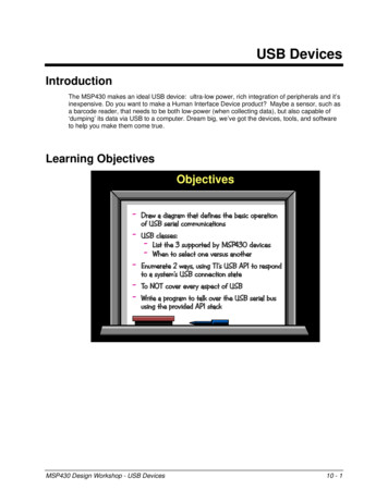
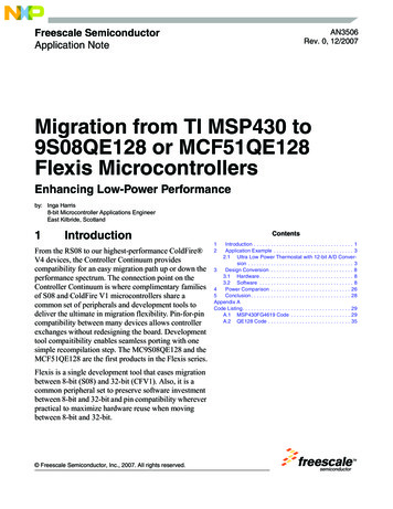
MSP430 Low-Power Modes (LPM)6 µs fromexternalor internalinterruptActive ModeCPU ActiveVarious Modules Active250 µALower Power Mode 0CPU OffSystem Clocks On30 µA6 µs fromexternalinterruptLower Power Mode 4Memory Storage ModeCPU & Clocks Off0.1 µA6 µs fromexternalinterruptLow Power Mode 3Ultra-Low-Power /Real-Time Clock ModeCPU Off/ ACLK On0.8 µAMSP430 Clock ModulesThe clock modules of the MSP430are fully programmable and offersystem designers an array ofclocking options. The DigitalController Oscillator (DCO) canbe programmed to supply a system frequency of 1 to 8 MHz.Typically the MSP430 only needsa single external 32 kHz crystal togenerate an accurate high-speedsystem frequency. Additionaladvantages of the 32 kHz crystalinclude low cost, direct division toreal-time using a single counterand the elimination of high frequency PCB layout. The 32 kHzsignal is available both internallyand externally when low frequencyis a requirement. The MSP430parts that include the FrequencyLocked Loop (FLL) circuit, automatically regulate the systemfrequency to a multiple of thecrystal.The DCO in all MSP430 productsstarts operation in a maximum of6 µs when an interrupt or resetoccurs. This allows the processorto stay in a low-power mode muchlonger and greatly reduces the timerequired to bring the part to anactive state, saving battery power.The MSP430 has a failsafe feature that allows the processor tostart operation using the DCO evenif the crystal fails. So even if thecrystal fails or is missing, theprocessor will still begin executingcode. This feature makes it possible to design MSP430 circuits thatdo not include a crystal.Features/PerformanceMSP430 Product RoadmapROM/OTP2.5 - 5 V LCD DriverFLLTimer/PortBasic Timer8-bit T/Cx33xFLASH1.8 - 3.6 VBasic ClockTimer AComparator A (notx 11x)F14xF4xxin designF13xSamples3Q 2000x32xF4xxLCD84ADC14F11x1in designTimer AComp Ax31x1996F4xxin designSamples3Q 2000LCD130Timer AUSARTMPYLCD92FLASH LCDF4xxx11xin designTimer A1999200042001
MSP430 Selection SP430F1354KBFlashROM8KB16KB256 bytes128 bytes256 bytes128 bytes256 bytes128 bytes256 bytes256 bytes512 bytes32KB48KB60KB1 KB2 KB2 RAM8KB16KB512 bytes512 bytes128 bytes256 bytes256 bytes512 bytes512 bytes512 bytes256 bytes512 ralsPins/Package15-bit Watchdog/Timer16-bit Timer A, 3 CC registersI/O Ports P1 & P215-bit Watchdog/Timer16-bit Timer A, 3 CC registersAnalog Comparator A, referencesI/O Ports P1 & P215-bit Watchdog/Timer16-bit Timer A, 3 CC registers16-bit Timer B, 3 CC/shadow registersAnalog Comparator A, references12-bit, 12-channel high-speed ADCHW USART, UART/SPI capabilitiesI/O Ports P1-P615-bit Watchdog/Timer16-bit Timer A, 3 CC registers16-bit Timer B, 7 CC/shadow registersAnalog Comparator A, references12-bit, 12-channel high-speed ADCTwo HW USART, UART/SPI capabilities8x8 to16x16 HW MPY/MACI/O Ports P1-P615-bit Watchdog/Timer8-/16-bit Timer Port64 or 92-segment LCD driverLow-Power UART HWI/O Port P020 SOP20 SOP20 SOP20 SOP, TSSOP20 SOP, TSSOP20 SOP, TSSOP20 SOP, TSSOP64 QFP64 QFP15-bit Watchdog/Timer8-/16-bit Timer Port84-segment LCD driverLow-Power UART HW14-bit HW ADCI/O Port P015-bit Watchdog/Timer8-/16-bit Timer Port120-segment LCD driverLow-Power UART HWHW USART, UART/SPI capabilities8x8 to16x16 HW MPY/MACI/O Ports P0-P4* UV-EPROM (E) versions available for prototyping - PMS430E112, PMS430E315, PMS430E325A and PMS430E337A564 QFP64 QFP64 QFP56 SSOP48 SSOP48 SSOP56 SSOP56 SSOP56 SSOP56 SSOP64 QPF, PLCC64 QPF, PLCC64 QPF, PLCC100 QFP100 QFP100 QFP
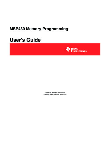
MSP430x11x(1) ConfigurationMSP430x11x(1) ConfigurationsThe low pin-count versions of theMSP430 products, theMSP430x11x and MSP430x11x1families, offer an unmatched combination of ultra-low-power consumption, Flash memory, 16-bitRISC performance and low cost.These devices consume as little250 µA in active mode, 0.8 µA instandby mode and 0.1 µA in off(RAM-retention) mode. With 1kflash, and volume 4k ROM pricesstarting as low as 0.99, the 11x(1)devices are quickly becomingthe benchmark in this price/performance category.The 16-bit RISC core operates atup to 8 MHz, allowing most of the27 core instructions to be executedwithin a 125 ns cycle. The 11x(1)devices are fully code compatiblewith all other members of theMSP430 family.Among the peripherals integrated into the 11x and 11x1 devicesare the 16-bit Timer A with threecapture/compare registers, 14individual I/O signals, the flexibleBasic Clock system, analogComparator A with references(11x1 only), Watchdog/Timer, andJTAG interface. The Basic Clocksystem allows standby times of upto 128 seconds. Program/datamemory sizes are 1 to 4K bytes.XOUTXINSystemClockRoscVCC VSS2/4KBROMMTPSMCLK 4KB'C': ROMACLKOscillatorincluding16 registerWatchdogHOSTPx.xRXPx.x8/0’s, allwith interr.capability15/16 bitMDB, 4 bitTACLKINCLK Comparatoror(11x1 only)CCI1BInputTimer ATimerACLKSMCLKI/O Port 1 JTAGMCBBusconvMDB, 16 bitTEST/VPPP1.7/TA2MAB, 4 bitTest/JTAG3CC RegisterCCR0/1/2OutxCCIxACCIxBMultiplexerRC filtered O/PIntenal VrefAnalog switchINCLKI/O Port 28 I/O's LKP2.2/CAOUTMSP430x11x(1) Application ExamplesThe MSP430x11x(1) series hasexpanded the reach of low-costsystem design. A real-time clock(RTC) or battery monitor/charger,with as much as 10 years of battery life, are just two applicationswhere a MSP430 device minimizessystem cost while dramatically simplifying design and reducing development time.These applications operateprimarily in low-power mode 3(LPM3), with the device interruptDCORACLKP2.5/RoscP2.4/CA1P2.3/CA0timing coming from an external32 kHz crystal oscillator. The11x(1) device periodically wakesup to update the time or to measure and adjust the chargingconditions. The pulse-width modulation (PWM) for the chargeris automatically generated evenwhile the device is in LPM3. Theextensive use of low-power modesallows system design engineers todesign applications that onlyrequire an average currentof 1.52 µA.Battery Monitor/Charger32 kHzTXSRAMMAB, 16 bitCPUReal-Time Clock/TimerXinP1.0/TACLKOutxPower- CCIxAOnTACLKReset SMCLK128/256 BRAM'F': Flash(MTP)MCLKRST/NMI32 kHzVbattXoutXinR1R2RrefXoutP2.3 (CA0) P2.4 (CA1) Px.xPx.xauto PWMPx.xPx.xPx.xUART, SPI, I2CRrefRtempMSP430x11x(1)P1.xP2.x MSP430x11x112 I/Osforexpansion& interfacingP1.xHOSTVCCTXPx.xRXPx.xUART, SPI, I2CVSSP2.xVCCVSSTPS769271.8 - 3.6 V63V 5 I/Osforexpansion& interfacing
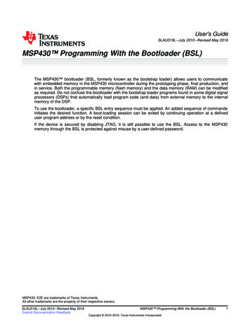
MSP430F13x ConfigurationP1 P2P3 P4P5P612 bit ADCI/O Port 1/2I/O Port 3/4I/O Port 5I/O Port 68 channels 10us conv.16 I/O's, withinterruptcapability16 I/O's8 I/O's8 I/O'sXIN XOUT/TCLK DVCC DVSS AVCC AVSS RST/NMIRoscACLKOscillator16KB Flash8KB FlashXT2INXT2OUTSystemClock512B RAM256B RAMSMCLKMCLKincluding16 registerMAB,4 bitMAB,16 bitTestJTAGCPUMCBBusconv.MDB,16 bitTMSMDB,8 bit4WatchdogTimerTCKTDIACLKTDOSMCLK15/16 bitMSP430F13x ConfigurationThe new MSP430F13x familyexpands the number of applications that can take advantage ofthe MSP430’s ultra-low-power performance. The family adds newmodules and features to enablemore applications to become truesystem-on-a-chip designs. The 12channel, 12-bit high-speed ADCincorporates buffer memory,Timer B3Timer A33 CC-RegisterShadow Reg.3 CC-RegisterPower onResetautoscan, internal voltage references, a temperature sensor andbattery monitor. The Timer Bmodule includes threecapture/compare registers withshadow capability. These workwith the integrated 8-, 10-, 12- or16-bit Timer B counter, which canoperate independently of the CPU.The 13x family also retains thepowerful Timer A in addition to3-Phase Motor ControllerVmotor32 kHz1.8 -3.6 VVCCComparatorXinXoutMSP430F13x internal temp. sense internal VCC senseTA0A0A1TB1tach inputmotor tempdrive voltageMauto 3ph PWMMotorDriveTB2TB3URXD.0HOST/System comm UART/SPIA2UTXD.0A3 - A7TA1 - TA2CA0, CA1, CAOUT28 additional I/Osdrive current39 addionalADC, analog,PWM, & I/Olines forexpansion & interfacingVSS7USART0UART modeSPI modeTimer B. The Basic Clock modulehas been expanded to allow ahigh-speed crystal to be used inaddition to, or substituted for, thestandard 32 kHz crystal. The dedicated hardware USART modulewith UART/SPI capability is alsoincluded. Flash memory optionshave been extended to 16K bytesin the 13x family.MSP430F13x Application ExampleThe new Timer B with shadowcapability allows three PWM signals to be changed simultaneously,making the 13x devices ideal formany motor control applications.The high-speed ADC allows up toeight channels to monitor sensorsfor closed-loop control.The hardware USART moduleallows straightforward interfacingvia UART or Serial PeripheralInterface (SPI) to a host or othersystem components.
MSP430F14x ConfigurationXIN XOUT/TCLKP1 P2P3 P4P5P612 bit ADCI/O Port 1/2I/O Port 3/4I/O Port 5I/O Port 68 channels 10us conv.16 I/O's, withinterruptcapability16 I/O's8 I/O's8 I/O'sDVCC DVSS AVCC AVSS LK2KB RAM2KB RAM1KB RAM60KB Flash48KB Flash32KB FlashMCLKincluding16 registerMAB,4 bitMAB,16 bitTestJTAGCPUMCBEmulationModuleBusconv.MDB,16 bitMDB,8 bit4TMSTCKWatchdogTimerHardwareMPYTDITDOACLK15/16 bitTimer B7Timer A37 CC-RegisterShadow Reg.3 CC-RegisterPoweronResetUSART0USART1UART modeSPI modeUART modeSPI modeSMCLKTimer B for a total of seven, asecond hardware USART module,with UART/SPI capabilities, thesingle-cycle, 16-bit hardware multiplier module is included, Flashmemory options of up to 60Kbytes and static RAM memory ofup to 2K bytes are available.MSP430F14x ConfigurationThe new MSP430F14x familyfurther expands on the capabilities of the 13x family and iscurrently the high-end solution ofthe non-LCD devices. Additionalcapabilities of the 14x familyinclude: four capture/compare/shadow registers added toHigh-End Security Panel8 MHzspeakerComparatorPWMXin2Xout232 kHzXinXoutPx.xTBOMSP430F14xA0modem signals3LED indicatorsPx.x9Px.xPx.xTRF6900900 MHzxcvrphonelineinterfacecircuitTRF6900orTRF4900(1 of n)keypad4Host comm URT/SPI9600 baudPx.xURXD.1UTXD.1 VCCmain power9/75/7 additional I/OsPx.xURXD.0UTXD.0Ax, Txx,VSS CAx, Px.xremotekeypadcommUART/SPIMSP430x11x14phone lineMSP430x11x1Px.xPx.xnTLV5606audio inputA1 internal temp. sense internal VCC sense Px.xwired zones & sensorsadditional I/O &analog signals444 additional I/Osbattery backup 1.8 - 3.6 V8MSP430F14x Application ExampleThe large selection of peripheralson the 14x devices make it wellsuited for many high-end controland monitoring applications. Thesecond hardware USART moduleallows for simultaneous communications with a host and othersystem components, as shown inthe example. The high frequencycrystal option on the Basic Clockenables the 14x to generate stable clock signals for applicationssuch as RF communications. Thehigh-frequency crystal can beturned off to save power whennot in use. The MSP430 is stillable to operate from its fast-start,high- frequency, internal DCO.The large number of high-speedADC, analog comparator and I/Opins allow a wide array of sensors, switches and other signalsto be interfaced directly to the14x.
MSP430x31x ConfigurationXIN XOUT XBUF VCC VSSOscillatorFLLSystemClockRST/NMIACLK 4/8/12/16KBMCLKTDITDOROM8/16KBOTP256/512BRAM'C': ROM'P': OTPSRAMP0.0 P0.7PowerOnReset8B Timer/ TXD I/O Port8 I/0’s, allCounterwith interrSerial Protocol RXD capabilitySupport3 lnt VectorsMAB,4 bitMAB,16 bitCPUTestJTAGincluding16 registerMCBBusconv.MDB,16 bitTMSTCKMDB,8 bitWatchdogTimer/PortTimerApplications:A/D Conv.Timer, O/P15 bitBasicTimer 1TP.0.5 CINfunction is not required, the module can be used as a 16-bit timeror as two 8-bit timers.The Watchdog/Timer modulecan be configured as a 15-bitwatchdog or as a 15-bit generalpurpose timer. The Basic Timerincludes two 8-bit timers forgeneral-purpose use. It generatesthe basic LCD frequency andsupports the real-time clockfunction.Digital Thermometer/Thermostat32 CD423VCCP0.0P0.3P0.4TP0.2Optional UART comm.TP0.4TP0.5P0.5P0.2 (TXD)P0.1 (RXD)VCCVSSP0.7InputSwitches 3 outputs& 1, 2, 3, 4 MuxCom0.3Seg 0.18,22,23,26Seg 27f LCD6MSP430x31x ConfigurationThe MSP430x31x family is themost cost-optimized version witha LCD driver in the MSP430product line.It can be used for sensor applications by measuring resistivevalues. The Timer/Port modulecan perform this resistive-todigital conversion by measuringthe charge/discharge time of anexternal capacitor. Where thisLCD92 Segments4 I/Os forexpansion& interfacing3V9R03 R13 R23 R33The LCD driver module can driveup to 92 segments in 1-to-4 MUXmode. Each pin of the I/O portcan be individually configured andeach has interrupt capability. The8-bit Timer/Counter supports serial communication protocols likeUART or I2C bus on the I/O port.The necessary software routinesfor this and many other modulesare listed in the MSP430Application Report book.MSP430x31x Application ExampleThe MSP430 requires very fewexternal components to form acomplete system. The low component count of the digital thermometer shown here ensures fastdesign cycle, maximum flexibilityand very competitive system cost.For resistive sensors, such asthermistors, the 16-bit singleslope A/D converter, implementedusing the Timer/Port module isideal. Three additional externalcomponents, a crystal (optional),the battery and the LCD display,are all that are needed for a complete system with the MSP430.
MSP430x32x ConfigurationXIN XOUT XBUF VCC VSSOscillatorFLLRST/NMI256/512BRAM8/16KBROMMCLK 16KB OTPACLKSystemClockP0.0 P0.7PowerOnResetSRAM'C': ROM'P': OTPTDITDOI/O Port8B Timer/Counter TXD 8 I/0’s, allSerialProtocolSupportwith interr.RXD capability3 lnt. VectorsMAB,4 bitMAB,16 bitCPUincluding16 registerTestJTAGMCBBusconv.MDB,16 bitTMSTCKADC12 12bitWatchdogTimer6 ChannelsCurrent S.15 bitMDB,8 bitTimer/PortApplications:A/D Conv.Timer, O/PBasicTimer 1LCD92 Segments1, 2, 3, 4 MuxfLCD66TP.0.5 CINA0.5 RI SVCCR33 R23 R13 R03full supply voltage range or toprovide 12-bit resolution in eachof four separate ranges. Theintegrated current source canbe programmed with an externalresistor to connect current-drivensensors.MSP430x32x ConfigurationThe MSP430x32x series offersa high-resolution A/D converterin addition to the peripherals ofthe MSP430x31x configuration.This 14-bit A/D converter has sixinputs to convert analog signalsto 14-bit digital values over theSingle-Phase Electricity MeterLiveLOADNuetral32 kHzRange 2.5 ent4.3MVoltageRef33k0VA0TP0.1EEPROMDataP0.0P0.1 (RXD)Optional UART comm.P0.2 (TXD)A4P0.3TP0.5TP0.2A5LMx85V refTP0.4P0.4AVSSDVSS-2.5 VCLKMSP430x32xA1Com0.3Seg 0.19Seg 20DVCCP0.7 2.5VInputSwitches 3 outputs&4 I/Os forexpansion& interfacing 2.5 V10MSP430x32x Application ExampleOne of many application areaswhere the MSP430 proves veryeffective is single-phase electricitymeters. The cost-competitivesingle-chip solution shown hereuses the 14-bit on-chip A/D converter to convert the current (viaa current transformer on A0) andvoltage (via a voltage divider onA1) into digital values. The symmetrical supply voltage enablessigned measurement, while theLMx85 creates a reference voltage. The amount of energy consumed is calculated by the CPUand the value displayed on theLCD or transmitted via theoptional UART connection.Nonvolatile data storage is possible with an optional externalEEPROM. A detailed applicationnote is available for this as well asmany other applications.
MSP430x33x ConfigurationXINXOUTXBUFVCC1 VCC2 VSS1ACLK24KB ROM32KB ROM32KBEPROMVSS2 VSS3RST/NMIP2.x P1.xP4.0 P4.78OscillatorFLLSystemClockSMCLKPower-OnReset1KB RAMSRAMTDITDOincluding16 registerTestJTAG8I/O PortI/O PortI/O Port1x8 dig. I/O's2x8 I/O's, allwith interr. cap2 Int. Vectors1x8 dig. I/O's8 I/O's, all withinterr. cap3 Int. VectorsTimer AMCBBusconv.MPY, MPYSMACWatchdogTimer16 x 16 bit8 x 8 bit15bitMDB,8 bitUSARTTIMER A16bit PWM8-bit Timer/CounterUART or SPIfunctionUTXURXUCKTACLK TA0.0.5 STE SIMO SOMITXDTimer/PortMSP430x33x ConfigurationThe MSP430x33x series focuses onhigh-end applications. It includesseveral additional, powerfulmodules.The hardware (HW) multipliermodule performs 16x16, 16x8,8x16 and 8x8 multiplication andaccumulations (signed, unsigned).After loading both operands intothe multiplier, the result is available after a single cycle.The Timer A module includesa 16-bit timer/counter and five6RXDcapture/compare registers, whichcan be fully configured by software. The capture mode is primarily used to measure externalor internal events from any combination of positive and/or negative edges. The compare mode isprimarily used to generate timingfor software or application hardware or to generate PWM outputsignals for various purposes.Examples are D/A conversionfunctions and motor controlapplications. Timer A can runPersonal Medical DeviceXinTLV5616XoutCOMxAnalog OutSCLKMSP430x33xSxxDINP4.3 (SIMO)CSP4.0TLV2541Analog InCLKP4.5 (UCLK)DataP4.4 TP0.4TP0.5P0.3P0.4P0.5P0.6P0.7VCCSample Present SwitchLCD4VSSKeypadURXD.0UTXD.0Optional UART comm.P1.3-7P2.0-7P3.0-7P4.1,723 I/Osforexpansion &interfacing3.3 V11BasicTimer 1Appl.'s: ADCTimer, O/PTP.0.5 CINSensorRXD, TXDMAB,4 bitMAB,16 bitMDB,16 bitTMSTCKP0.0 P0.7I/O PortUARTCPUP3.0 P3.7f LCDLCD30 SegmentLines1,2,3,4 MuxCom0.3S0.28/O2.28S29/O29/CMPICMPIR03 R13 R23 R33independently of the CPU, allowing it to still be active in LPM3.The USART module featurestwo serial communication modes,a standard asynchronous communication protocol (UART, up to115.2 kBaud) and a SPI function.The mode is selectable by software via a control register. The33x series’ LCD module offers 30segment lines to drive up to 120segments in 4MUX mode.MSP430x33x Application ExampleThe array of modules and numberof I/Os on the MSP430x33x makeit well suited for high-end applications that require demanding userand hardware interfaces. Theexample circuit shown here canmaintain the LCD display andawait keypad interrupts whileoperating in LPM3. When interrupted, the circuit switches toactive mode, with the high-speedMCLK running, in less than 6 µs.While in LPM3 the circuit is fullyoperational from a user’s perspective, but the MSP430 is drawingless than 2 µA of current.
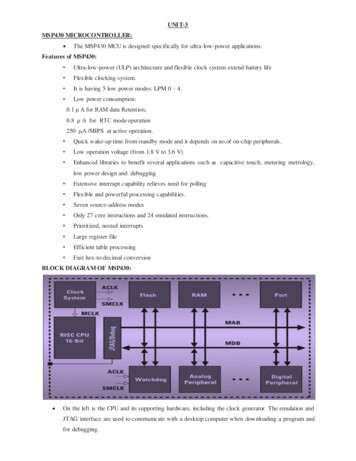
Kickstart User InterfaceMSP430 Design SupportKickstart EnvironmentKickstart is a fully integratedWindows-based developmentenvironment. It is derived fromthe popular IAR Workbench userinterface. This one interfaceallows the user to develop code,simulate operation, downloadsoftware and debug applicationsfor all MSP430 derivatives.Kickstart allows the setting ofbreakpoints and the monitoringof special function registers,memory, the stack, as well asother useful information.Kickstart includes the IARassembler, a software simulator,a limited version of the IAR Ccompiler and the C-SPY debugger. Upgrading to the full versionof IAR C is simple and does notrequire the user to learn a newinterface. MSP430 devices withFlash, OTP or UV-EPROM memory can be programmed directlyfrom Kickstart using either aFlash Evaluation Tool (FET) orthe serial programming adapter.MSP430 Flash EvaluationToolsMSP-FET430x110, MSP-FET430P140The new Flash evaluation tools,combined with the IAR Kickstartenvironment, enable systemdesigners to quickly update,download, run and debug theircode without ever disconnectingthe MSP430 from the PC. Thisgreatly speeds the developmentand debug portions of theapplication development cycle.12MSP - FET430x110Flash Evaluation Tool
The FET tools allow designers theflexibility of operating the deviceunder JTAG control, running tointernal breakpoints or free running the MSP430. Each FETcomes with an evaluation board,two Flash devices, PC parallelconnection, development softwareand the MSP430 CD-ROM. TheMSP-FET430x110 is a completelow-cost application developmentfor MSP430F11x1 products.The MSP-FET430P140 supportsapplication development for boththe MSP430F13x andMSP430F14x product families. Itincludes a parallel interface thatalso allows direct in-circuit programming of MSP430 Flashdevices.MSP430 Evaluation KitsMSP-EVK430S320 and MSPEVK430S330The MSP430 evaluation kits (EVK)are powerful development toolsthat include much of the hardwareand software required to completeyour application development.Each EVK comes with an evaluation board, two UV-EPROMdevices, serial programmingadapter, development software andCD-ROM. The MSP-EVK430S320EVK supports the MSP430x32xand MSP430x31x families ofdevices. The MSP-EVK430S330EVK supports the MSP430x33xand MSP430x31x families ofdevices.MSP430 Serial ProgrammingAdapterMSP-PRGS430The serial programming adapter isa second-generation programmingtool that can program any MSP430Flash, OTP or UV-EPROM device.Devices can be programmed instand-alone sockets or in-circuit.Software is included to facilitatedevice programming.MSP430 Development Tools*MSP430P112**DevelopmentEnvironmentKickstartC IARProgrammersMSP-PRGS430,BP, Data I/OMSP-PRGS430,BP, Data I/OMSP-PRGS430,BP, Data I/OMSP-PRGS430,BP, Data I/OMSP-PRGS430,BP, Data I/OMSP-PRGS430,BP, Data I/OMSP-PRGS430,BP, Data I/O*Third party tools are sold and supported by the third party companies offering them**UV-EPROM (E) versions available for prototyping - PMS430E112, PMS430E315, PMS430E325A AND 330MSP-EVK430S320MSP-EVK430S330
MSP430 Third-Party SupportTI maintains a dedicated MSP430third-party program for hardwareand software tooling as well as forprogramming support. Thesethird-party developers have theengineering expertise to provideapplication-specific software tools,helping our customers achievetheir design goals. Links from TI’sMSP430 web site will direct you toeach company’s home page:www.ti.com/sc/msp430BP Microsystems Inc.BP Microsystems Inc. designs andmanufactures device programmersfor both engineering and production applications. Leading theindustry in device support, performance and cost of ownership, BPprovides complete device programming solutions to customers worldwide. The company offers a full lineof single-site device programmersand Universal Programmers, andmulti-site Concurrent ProgrammingSystems.The MSP430 can be programmedusing any of BP’s universal engineering programmers (BP-1200and BP-1400), BP’s manualor multi-site ConcurrentProgramming Systems. For moreinformation, visit the BP web site:www.bpmicro.comData I/O CorporationUniversal Programming System SprintData I/O has invested heavily in thesteadily growing market of microcontroller devices by considerablyexpanding its device library. Theuniversal programming systems ofthe Sprint family not only standoutfrom most other programmingsystems through the variety ofsupported devices, but also byguaranteeing its customers the useof vendor approved algorithmswith maximal programming yieldsand minimal programming times.Data I/O supports TI’s MSP430devices with the universal programmers Sprint Multisystem aswell as with the automatic programming systems PP100. With thelatest version of the Sprint software, the following devices aresupported: MSP430x31x,MSP430x32x, MSP430x33x andMSP430x11x(1). All these controllers are supported with flexibleTOPs or adapters for differentpackages like PLCC, SSOP or QFP.Special software functions of thedevices, such as UserID, WatchdogTimer or Code Protection can beactivated via a simple menu. Formore information, visit the DataI/O web site:www.dataio.comHitex Emulator in an AffordableQuality ConceptWith the DProbe430, Hitex offers amodular emulation system which isspecifically designed to develop,test and optimize MSP430 applications. Starting with the entry-levelsystem DProbe430, up to the highend system DBox16, real-timedebugging at the highest frequencies and with all the power savingmodes is now possible withoutrestrictions. Changing from onederivative to another can be doneby an easy and low-cost exchangeof the derivative specific part. Thisalso allows an upgrade to futurederivatives.For reliable adaptation to thetarget hardware, adapters for all14available microcontroller packagesare supported.With the convenient and easy tolearn HiTOP user interface, all theprocessor internals and applicationstructures are made transparent.Symbolic high-level languagedebugging, as well as examinationdown to assembler code, can bedone to speed up the developmentand e
active. The MSP430 architecture includes an array of powerful and highly flexible peripherals that are also optimized for ultra-low-power operation. A key to the MSP430 perfor-mance is its unique ultra-low-power modes. The MSP430 is able to switch from ultra-low-power standby mode, where it only draws 0.8 µA of current, to full active mode in .