Transcription
TelosRev B (Low Power Wireless Sensor Module)TelosUltra low power IEEE 802.15.4 compliant wireless sensor moduleRevision B : Humidity, Light, and Temperature sensors with USBProduct DescriptionTelos is an ultra low power wireless modulefor use in sensor networks, monitoringapplications, and rapid applicationprototyping. Telos leverages industrystandards like USB and IEEE 802.15.4 tointeroperate seamlessly with other devices.By using industry standards, integratinghumidity, temperature, and light sensors,and providing flexible interconnection withperipherals, Telos enables a wide range ofmesh network applications. Telos Revision B is a drop-in replacement for Moteiv’s successfulRevision A design. Revision B includes increased performance, functionality, and expansion.With TinyOS support out-of-the-box, Telos leverages emerging wireless protocols and the opensource software movement. Telos is part of a line of modules featuring on-board sensors toincrease robustness while decreasing cost and package size.Key Features 250kbps 2.4GHz IEEE 802.15.4 Chipcon Wireless TransceiverInteroperability with other IEEE 802.15.4 devices8MHz Texas Instruments MSP430 microcontroller (10k RAM, 48k Flash)Integrated ADC, DAC, Supply Voltage Supervisor, and DMA ControllerIntegrated onboard antenna with 50m range indoors / 125m range outdoorsIntegrated Humidity, Temperature, and Light sensorsUltra low current consumptionFast wakeup from sleep ( 6µs)Hardware link-layer encryption and authenticationProgramming and data collection via USB16-pin expansion support and optional SMA antenna connectorTinyOS support : mesh networking and communication implementationMoteiv CorporationTelos (Rev B) : PRELIMINARY Datasheet (12/5/2004)Page 1 of 28
TelosRev B (Low Power Wireless Sensor Module)Table of ContentsModule Description .3Power .4Typical Operating Conditions .4Mechanical Characteristics .5Block Diagram.6Schematic .7Microprocessor .9Description .9Typical Operating Conditions .9PC Communication .9Programming.10Block Diagram.12Radio.13Description .13Typical Operating Conditions .14Measured Output Power .14Antenna.15Internal Antenna.15Internal Antenna without Battery Pack .16Internal Antenna with Battery Pack .16Radiation Pattern .17SMA Connector.18External Flash .19Typical Operating Conditions .19Flash Hardware Write Protection .20Sensors.21Humidity/Temperature Sensor .21Light Sensors .22Expansion Connector.23Internal Temperature and Voltage Monitoring.25General Information .26Document History.26Product Status Definitions.26Disclaimer .27Address Information .28Headquarters .28Moteiv CorporationTelos (Rev B) : PRELIMINARY Datasheet (12/5/2004)Page 2 of 28
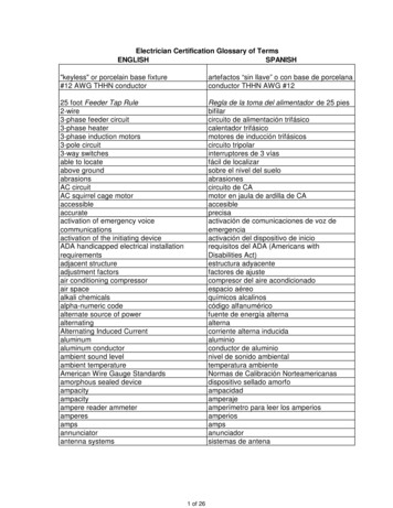
TelosRev B (Low Power Wireless Sensor Module)Module DescriptionThe Telos module is a low power “mote” with integrated sensors, radio, antenna,microcontroller, and programming capabilities.UserButtonUSB Transmit LEDHumidityPhotosyntheticallyTemperatureActive l SolarButtonRadiation6-pin expansionSensorconnector(optional)10-pin expansionconnectorUSBConnectorInternalAntennaUSB Receive LEDLEDsUSBMicrocontrollerDigital switchIsolating USB frommicrocontrollerJTAGconnectorTexas InstrumentsMSP430 (optional)48-bit siliconserial ID2-pin SVSconnectorUSBFlash (2kB)32kHzoscillatorST CodeFlash (1MB)Figure 1 : Front and Back of the Telos moduleMoteiv CorporationTelos (Rev B) : PRELIMINARY Datasheet (12/5/2004)Page 3 of 28
TelosRev B (Low Power Wireless Sensor Module)PowerTelos may be powered by two AA batteries. The module was designed to fit the two AA batteryform factor. AA cells may be used in the operating range of 2.1 to 3.6V DC, however thevoltage must be at least 2.7V when programming the microcontroller flash or external flash.If the Telos module is plugged into the USB port for programming or communication, it willreceive power from the host computer. The mote operating voltage when attached to USB is3V. If Telos will always be attached to a USB port, no battery pack is necessary.The 16-pin expansion connector (described in the Section on page 19) can provide power to themodule. Any of the battery terminal connections may also provide power to the module. At nopoint should the input voltage exceed 3.6V—doing so may damage the microcontroller, radio, orother components.Typical Operating ConditionsSupply voltageSupply voltage during flash memory programmingOperating free air temperatureCurrent Consumption: MCU on, Radio RXCurrent Consumption: MCU on, Radio TXCurrent Consumption: MCU on, Radio offCurrent Consumption: MCU idle, Radio offCurrent Consumption: MCU sensitivedevice.Precaution should be used when handlingthe device in order to prevent permanentdamage.Moteiv CorporationTelos (Rev B) : PRELIMINARY Datasheet (12/5/2004)Page 4 of 28
TelosRev B (Low Power Wireless Sensor Module)Mechanical CharacteristicsO n -b o a rd a n t e n n a ; d o n o t c o v e rw it h c o n d u c t in g m a t e ria s0.183 0.099 Ø 0.090 Mounting hole, do not use metal fixture2.454 0.099 Ø 0.090 Mounting hole2.454 1.151 Ø 0.090 Mounting hole0.755 0.162 Ø 0.066 Pin 1 of 10-pin 0.1in rect IDC connector1.099 0.163 Ø 0.066 Pin 1 of 6-pin 0.1in rect IDC connector2.139 0.909 Ø 0.034 Pin 1 of 8-pin 2mm rect JTAG connectorFigure 2 : Physical dimensions of Telos Revision B.All units are in inches unless otherwise noted.WidthLengthHeight (without battery pack and SMA antenna)Moteiv CorporationMIN1.242.550.24NOM1.262.580.26Telos (Rev B) : PRELIMINARY Datasheet (12/5/2004)MAX1.292.600.27UNITinininPage 5 of 28
TelosRev B (Low Power Wireless Sensor Module)Block DiagramPCBAntennaCC2420 Radio2.4 GHzIEEE 802.15.4 ADC[5]JTAG 8-pin2mm IDC headerJTAGSPI[0]I/OP1[0,3,4]P4[1,5,6]TI MSP430 set10-pin 6-pinIDC headerHumidityTemperatureSensorSilicon Serial ID1-wireI/OUserUART[1] ResetP1.1/P2.2 TCK I2C[0]22Power7SVSin4RX/TX RTS/DTRJTAGUSB 2.0UART/RS232FunctionalitySVS 2-pinIDC headerSPI[0] SVSoutWrite ProtectionST Flash1024k (2.7V)Figure 3 : Functional Block Diagram of the Telos Module, its components, and busesMoteiv CorporationTelos (Rev B) : PRELIMINARY Datasheet (12/5/2004)Page 6 of 28
TelosRev B (Low Power Wireless Sensor Module)Schematic54312R1S E N S OR SINVref F L A SH H O L DR A D I O R E S ETR A D I O V R EF ENF L A SH C SPr e v Fl a s h PwrRADIO CS37R A DIO XP3.5/URXD033UART0RXDL212F Be a d 2 4 0 - 1 0 3 5 - 1OPTI ONALR 121 0 0 k 1%122UART0RX44UART0TX66I 2 C SC L88I 2 C SD A3577991010SW2A DC3U s e r IN T21EVQ-P2K02QG IO 0ACL KU 28C90 .1 u0 openA DC61 1DAC0G IO 23Ti me r A Ca p t u r e 3U s e r IN T5 5A DC7DAC1 / SVSi nG IO 3DMAE0RESET622446R 15M O U N T ING HO L ESS V S out0 open6 pin Header1P3.4/UTXD0J TA 1DV CCDV CCD4SQWVssL ED 12D5U51234R71R e d C l e a r - 404-1017-1-ND470F L A SHF L A SH C SR A D IO SOP DVCCBJ12No n p l a t e dn e ar ant ennaL EDSRESET8 p i n H e a d e r - 2m mR22.2kVccHOLDCD8765R81DV CCF L A SH H OL DR A D I O SC L KRADIO SIL ED 22G r e e n C lear - 4 0 4 - 1 0 2 1 - 1 - N D220C60 .1 uR9D61L ED 32B l u e C le a r - 4 0 4 - 1 0 2 8 - 1 - N D100S E R IA L IDAU91Wire1I/O VccGND23DV CCTitleSizeBD S2 4 1 1D a te:432432Tel o sD o c u ment NumberR evB(c ) Co p y r i g h t 2004: UC B er k el eyWednesday, September 29, 2004S h eet1of311C 641 0 u F L o w E SR 5 o h mNC373938XOSC16 Q2CC24K DVDD40CC24K DVDD341VREG ENVREG OUT42444345R BIASVREG INAVDD IF14746ATEST2AVDD XOSC1632R A D I O SC L KCSn31RADIO CSFIFO30R A D IO G IO 0FIFOP29CCA28R A D IO G IO 1AVDD SWSFD27R A DIO SFDDVDD1.826C C 2 4 K D VD DDVDD3.325C C 2 4 K D VD D 313BDSUB CORENC2 . 4 GHz ma t c h i n g n e t wo r kCC2420PKT INT24NCDGNDNC12RESETn11DSUB PADSRF N21C 810 . 5 p / - 0 .2 5 p n p 0RADIO SISCLKGNDDGUARD7 .5 n 5 %a t 2 . 4 GHzma t c h e d t o 5 0 o h msCR 4 761 0kR A D IO SO8102TXRX SWITCHC C 2 4 K D VD D 3R 4 7410kC C 2 4 K D VD D9DGND GUARD1RF P20L81u s e 50 ohm t r ac esGND19133AVDD RF1575 . 6 p 1 0 % x5 rSI46DVDD ADC115 . 6 p / - 0 .2 5 p n p 034AVDD ADC2L617 .5 n 5 %SONCC 71DVDD RAMAVDD PRE1832AVDD VCO17L625 .6 n 5 %C C 2 4 K D VD D 33635162C C 2 4 K AVD DNC3DC 3 812 2 p 5% np01 6 MH Z - 1 6pfGND EXAVDD IF20 . 5 p / - 0 .2 5 p n p 0C 73C3912 2 p 5% np0X1VCO GAURD U 102AVDD RF2C 61ATEST1481AVDD CHP4915CC24K AVDDA2SMA1C14123GNDGNDGNDRF GND5432A1C C 2 4 2 0 PC B AN TDVCCC80 .1 uR 4 731mR 4 750R 4 5143k 1%L32F Be a d 2 4 0 - 1 0 3 5 - 1C7 i s o l a t i o n0 .1 uC C 2 4 K D VD D 3 1R A D I O V R EF ENXOSC16 Q1C 870 .1 u23C 8668p22C 850 .1 uC 8410nCC24K AVDDC 8368pCC24K AVDDC C 2 4 K D VD DDBCR44 7 0kU S E R S W I TC HR141 0 p i n H e a d e r - 0 .1 "UART1RXRESET2DV CCM25P80C 8268pC310uFEVQ-P2K02Q5DV CC5DV CCR E S E T S W I TC HRADIO SIC C 2 4 K AVD DDVCCC20 . 1u1A DC1R A D IO SO5DV CCC10 .1 uD3S1087-01 Photodiode0 openR A D I O SC L KA2SVS outPW R C O NNV C C in3G IO IO SOI2C SDA RADIO AINCLKP2.0/ACLK20191817HUM SDAHUM PWRHUM /TA0R A D I O G IO 0R A D I O G IO 1P2.2/CAOUT/TA0/BSLRXTI MSP430 F1611I2C SCL RADIO 1R 16P4.3/TB313H U M S D AA DC0A DC2P4.2/TB214H U M S C L2A DC5AV CCVref-/VeREF-P DVCC2SW1P1.0/TACLKUART1TX3SDAU2VeREF P DVCC12 p i n H e a d e r - 2m mE X P A N S ION11UART1TXSCLKOPTI ONALR 111 0 0 k 1%1222PKT INTP4.7/TBCLKMCU213 2kHzR55 .1 M67GIO1A DC7S V S in 1V C C in1P5.1/SIMO1S V S inU7V C C 846A DC6 .2/A2P6.3/A33D AC0GND363P5.4/MCLK2A DC4DVccVCCGNDD2S1087 PhotodiodeL ED 110kSHT11OPTI ONALA DC4A DC3A DC5X0U01C50 .1 u481U4R 10U3HUMI DI TY/TEMP SENSOR46264AVccDV CCP O WE RH U M P W R0 .1 uAVssDDVssAVCCC4ADC1ADC21 0 0kC C 2 4 K AVD DC C 2 4 K D VD DC C 2 4 K D VD DR A D I O R E SETR4721mC C 2 4 K D VD D 3AATitleSizeBD a te:5Moteiv Corporation432Telos (Rev B) : PRELIMINARY Datasheet (12/5/2004)Tel o sCC2420 802.15.4 Wi r el es s Rad i oD o c u ment Num berR evB(c ) Co p y r i g h t 2004: UC B er k el eyWednesday, September 29, 2004S h eet2of31Page 7 of 28
TelosRev B (Low Power Wireless Sensor Module)5432U S B P OW E R F I L T E R1MOTE POWERUSB INTERFA CE1127U VCC8USBDM7USBDP1 .5k5427X3GND3E EC SEESKEEDATAR 321m216 M r e s o n a to DATATESTFT232BMP DVCC1V C C in2V C C in11330326VCCTXDRXDRTS#CTS#DTR#DSR#DCD#RI#XTINP DVCCGNDVoutVin2L L SD 1 0 3 AR 291 0kC2510uDU VCCU 25T C 5 5 R P3 3C 220 . 1uVCCIO3V3OUTU SBU SB R 24R 23VCC6R 22273C 240 . 1uTXDRXDRTSDSRD TRU S B ID E N T I F I C A T ION EEPROMD20R 25D CDRI21 001E EC S1CSVCC8EESK2SKNC7EEDATAR 273DINNC64DOUTGND5G r e e n C lear - 4 0 4 - 1 0 2 1 - 1 - N DD21R 2621 00U 23U V C C 3 .31R e d C l e a r - 404-1017-1-ND2.2kGND2GND3AGND43294U SB ACU 20AVCC0 . 1uC 2133nU V C C 3 .3R 20470U AVCCC 230 . 1uU VCCC9 3 C46R28U VCC17C20U 22P DVCCU VCC2F Be a d 2 4 0 - 1 0 3 5 - 1129L20DD 22U VCCUsed for Reading Serial / ProgrammingConnects and Powered via USB10kI/O B UFFERR E S E T S E QU E N C E R E C OGN ITION1Y6P DVCCUART1TX752OE2A2Y3UART1RXUART1RXRXDD TRRTS31232422VCCDV CCTD OTDITMSTCKTCKR ESETR 3010kTCKSDASCLKRSTA0A1214P DVCCBA D G 7 1 5 BR UD8 1 9D7 1 7TDOD6 15TDID5 13TMSD4 12TCKD3 10TC K8D2RESET6D1GND1OE1AVSS12S8S7S6S5S4S3S2S14DV CC8P DVCCTXDGndUART1TXD CDRIDSRD TRN C7W Z126VccU 29U 2720181614119752DV CCDVCCDVCCBAATitleSizeBD a te:5432Tel o sUSB In t er f ac eD o c u ment NumberR evB(c ) Co p y r i g h t 2004: UC B er k el eyWednesday, September 29, 2004S h eet3of31Figure 4 : Schematics for the Telos module (Rev B)Moteiv CorporationTelos (Rev B) : PRELIMINARY Datasheet (12/5/2004)Page 8 of 28
TelosRev B (Low Power Wireless Sensor Module)MicroprocessorDescriptionThe low power operation of the Telos module is due to the ultra low power Texas InstrumentsMSP430 F1611 microcontroller featuring 10kB of RAM, 48kB of flash, and 128B of informationstorage. This 16-bit RISC processor features extremely low active and sleep currentconsumption that permits Telos to run for years on a single pair of AA batteries. The MSP430has an internal digitally controlled oscillator (DCO) that may operate up to 8MHz. The DCOmay be turned on from sleep mode in 6µs, however 292ns is typical at room temperature.When the DCO is off, the MSP430 operates off an eternal 32768Hz watch crystal. Although theDCO frequency changes with voltage and temperature, it may be calibrated by using the 32kHzoscillator.In addition to the DCO, the MSP430 has 8 external ADC ports and 8 internal ADC ports. TheADC internal ports may be used to read the internal thermistor or monitor the battery voltage.A variety of peripherals are available including SPI, UART, digital I/O ports, Watchdog timer,and Timers with capture and compare functionality. The F1611 also includes a 2-port 12-bitDAC module, Supply Voltage Supervisor, and 3-port DMA controller.The features of the MSP430 F1611 are presented in detail in the Texas InstrumentsMSP430x1xx Family User’s Guide available at http://ti.com/msp430.Typical Operating ConditionsSupply voltage during program executionSupply voltage during flash memory programmingOperating free air temperatureLow frequency crystal frequencyActive current at Vcc 3V, 1MHzSleep current in LPM3 Vcc 3V, 32.768kHz activeWake up from LPM3 (low power UNITVVoCkHzµAµAµsPC CommunicationTelos uses a USB controller from FTDI to communicate with the host computer. In order tocommunicate with the mote, the FTDI drivers must be installed on the host. FTDI providesdrivers for Windows, Linux, BSD, Macintosh, and Windows CE. These drivers are included onthe Moteiv CD shipped with your order. Windows users will need the Virtual Com Port (VCP)drivers. They may also be downloaded from FTDI’s website at: http://www.ftdichip.com/After installing the driver, Telos appears as a COM port in Windows’ device manager (or as adevice in /dev in Linux, OSX, and BSD). Multiple Telos motes may be connected to a singlecomputer’s USB ports at the same time. Each mote will receive a different COM port identifier.In the example below, one Telos is connected and assigned COM6 “USB Serial Port”.An application may read from Telos by opening the COM port assigned to the Telos mote.Telos communicates with the host PC through USART1 on the TI MSP430.Moteiv CorporationTelos (Rev B) : PRELIMINARY Datasheet (12/5/2004)Page 9 of 28
TelosRev B (Low Power Wireless Sensor Module)Figure 5 : Device Manager showing Telos installed as COM6The motelist command line utility lists all of the Telos motes currently connected to acomputer. This utility optionally lists previously connected motes that the system has cached.Invoke motelist with the -h option for more information. motelistReference CommPortDescription---------- ---------- 6Telos (Rev B 2004-09-27)NOTE: Telos (Revision B) uses an I2C digital switch to prevent unwanted conventionalserial port signals from reaching the TI microcontroller. The I2C protocol must beimplemented and sent over the RTS and DTR lines in order to obtain direct accessbetween the Telos and USB controller. The UART lines do not use the I2C switch allowingdirect communication (but not programming or JTAG) without additional software.ProgrammingThe Telos module is programmed through the onboard USB connector. A modified version ofthe MSP430 Bootstrap Loader, msp430-bsl, programs the microcontroller’s flash. Telos has aunique hardware circuit that prevents the mote from spuriously resetting. This hardware circuitmakes it necessary to have a special sequence sent to the module in order to program it.By invoking msp430-bsl, verify you have the patched BSL by looking for the “telos” keyword.Version 1.39-telos-6 or later is required for Telos (Rev B). msp430-bslMSP430 Bootstrap Loader Version: 1.39-telos-6Use -h for helpMoteiv CorporationTelos (Rev B) : PRELIMINARY Datasheet (12/5/2004)Page 10 of 28
TelosRev B (Low Power Wireless Sensor Module)To communicate with Telos, the MSP430 Bootstrap Loader requires a set of options to providethe proper signals to the microcontroller to initiate programming. For convenience, the optionshave been folded into a single Telos (Revision B) flag:--telosbTo program a Telos module on COM3 (or /dev/ttyUSB2 in Linux) with an application imagenamed app.ihex, invoke the MSP430 Bootstrap loader with the following options. msp430-bsl --telosb -c 2 -r -e -I -p app.ihexMSP430 Bootstrap Loader Version: 1.39-telos-6Mass Erase.Transmit default password .Invoking BSL.Transmit default password .Current bootstrap loader version: 1.61 (Device ID: f16c)Changing baudrate to 38400 .Program .2742 bytes programmed.Reset device .If you are using TinyOS, it has support for programming Telos. After compiling your application,you may install it with the following command make telosb install.x bsl,nWhere x is the 16-bit address assigned to the mote and n is the COM port that Telos iscurrently using. Note that not including “bsl” or “bsl,n” will program automatically using thebsl to the first Telos mote found on the USB bus using the motelist command.For more information about the options in the MSP430 Bootstrap loader, invoke msp430-bslwith the -h option to display the help information.Motelist and msp430-bsl are available from Moteiv Corporation at http://www.moteiv.com inthe “Support” section.NOTE: msp430-bsl starts counting from 0, but COM ports in Windows start counting at 1.If Telos is connected to COM3 in Windows, you must program it using “-c 2” or “bsl,2”when invoking msp430-bsl. In Linux, Telos will appear as /dev/ttyUSB2 and may beprogrammed using “-c 2” or “bsl,2”.Moteiv CorporationTelos (Rev B) : PRELIMINARY Datasheet (12/5/2004)Page 11 of 28
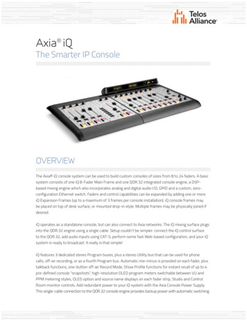
TelosRev B (Low Power Wireless Sensor Module)Block 12-bit ADC8 Channels 10µs Conv12-bit DAC I/O Port 1/2 I/O Port 3/4 I/O Port 5/616 I/Os16 I/Os8 I/Os2 ChannelsInterruptsMCLK16-bit busCPU16 bit16 regmultiplyDMAController3 ChannelsWatchdogTimer15/16 bitTimer A3 CC regTimer B7 CC regComparatorAUSART0UARTSPII 2CUSART1UARTSPICC2420 RadioInterrupts & SPIPCUART via USBFigure 6 : Block diagram of the TI MSP430 microcontroller and its connection to other peripheralsin the Telos moduleMoteiv CorporationTelos (Rev B) : PRELIMINARY Datasheet (12/5/2004)Page 12 of 28
TelosRev B (Low Power Wireless Sensor Module)RadioDescriptionTelos features the Chipcon CC2420 radio for wireless communications. The CC2420 is anIEEE 802.15.4 compliant radio providing the PHY and some MAC functions. With sensitivityexceeding the IEEE 802.15.4 specification and low power operation, the CC2420 providesreliable wireless communication. The CC2420 is highly configurable for many applications withthe default radio settings providing IEEE 802.15.4 compliance. Features and usage of theCC2420 is available in Chipcon’s datasheet at http://www.chipcon.comThe CC2420 is controlled by the TI MSP430 microcontroller through the SPI port and a series ofdigital I/O lines and interrupts (see the Schematics on page 7 for more information). The radiomay be shut off by the microcontroller for low power duty cycled operation.The CC2420 has programmable output power. Common CC2420 register values and theircorresponding current consumption and output power are shown in Figure 7.PA LEVEL31272319151173Current Consumption [mA]TXCTRL register Output Power 5Figure 7 : Output power configuration for the CC2420The CC2420 provides a digital received signal strength indicator (RSSI) that may be read anytime. Additionally, on each packet reception, the CC2420 samples the first eight chips,calculates the error rate, and produces a link quality indication (LQI) value with each receivedpacket. A mapping from RSSI to the RF level in dBm is shown in Figure 8.Figure 8 : Received Signal Strength Indicator mapping to RF Power [dBm]Moteiv CorporationTelos (Rev B) : PRELIMINARY Datasheet (12/5/2004)Page 13 of 28
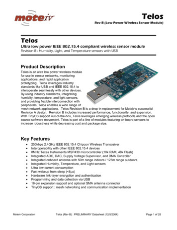
TelosRev B (Low Power Wireless Sensor Module)Typical Operating ConditionsSupply voltage during radio operation (Vreg on)Operating free air temperatureRF frequency rangeTransmit bit rateNominal output powerProgrammable output power rangeReceiver sensitivityCurrent consumption: Radio transmitting at 0 dBmCurrent consumption: Radio receivingCurrent consumption: Radio on, Oscillator onCurrent consumption: Idle mode, Oscillator offCurrent consumption: Power Down mode, Vreg offVoltage regulator current drawRadio oscillator startup mAmAµΑµΑµΑµΑµsMeasured Output PowerThe RF output power of the Telos module from the CC2420 radio is shown in Figure 9. For thistest, the Telos module is transmitting at 2.405GHz (IEEE 802.15.4 channel 11) using the OQPSK modulation with DSSS. The CC2420 programmed output power is set to 0 dBm. Themeasured output power of the entire modulated spectrum is 2.4 dBm.0RWB: 100 kHzVWB: 100 kHzSweep: 50ms 5 10Output power (dBm) 15 20 25 30 35 40 45 502.42.4012.4022.4032.4042.4052.406Frequency (GHz)2.4072.4082.4092.41Figure 9 : Measured RF output power over the modulated spectrum from the Telos moduleMoteiv CorporationTelos (Rev B) : PRELIMINARY Datasheet (12/5/2004)Page 14 of 28
TelosRev B (Low Power Wireless Sensor Module)AntennaTelos has two antenna options—and internal antenna built into the module and an external SMAconnector for connecting to external antennas. By default, Telos is shipped with the internalantenna enabled. If an application requires an external antenna or a different directional patternthan the internal antenna, an SMA connector may be installed and an antenna may beconnected directly to Telos’ SMA female connector.In order to switch between the internal antenna and the SMA connector, the capacitor at C73must be moved from the two left pads to the two right pads connecting the radio to the SMAconnector. This process may be completed quickly with a heat gun and tweezers by sliding thecapacitor over to the adjacent pad once the solder begins to melt.To InternalAntennaTo SMAConnectorFigure 10 : Moving C73 to select between the internal antenna and the SMA connectorInternal AntennaTelos’ internal antenna is an Inverted-F microstrip design protruding from the end of the boardaway from the battery pack. The Inverted-F antenna is a wire monopole where the top sectionis folded down to be parallel with the ground plane. Although not a perfect omnidirectionalpattern, the antenna may attain 50-meter range indoors and upwards of 125-meter rangeoutdoors. Measurements of the internal antenna’s performance with and without a battery packare show in Figure 11 and Figure 12. Approximate radiation patterns for the Inverted-F antennaas provided by Chipcon AS are shown in Figure 13 and Figure 14.Moteiv CorporationTelos (Rev B) : PRELIMINARY Datasheet (12/5/2004)Page 15 of 28
TelosRev B (Low Power Wireless Sensor Module)Internal Antenna without Battery Pack2004/11/25 Thr 14:44:06CH2 S11SMITH(R jX)FS01.000MKR 3: 2.483 958 333GHz65.1664.083 51 10Cor4 15Log( S11 ) (dB)2323 20 25 30 351 401:2.400 000GHz2:2.450 000GHz3:2.483 958GHz40.01439.75765.041START 2.3GHz-40.598-4.6234.227[ 10.00 dBm]1.633pF14.050pF270.843pHSTOP 2.55GHz1:2:3: 45 4:2.400 GHz2.450 GHz2.485 GHz2.500 GHz 502.32.325 7.40 dB 16.58 dB 16.58 dB 12.50 dB2.352.3752.42.4252.452.4752.52.5252.55Frequency (GHz)Figure 11 : S11 measurements for the internal inverted-F antenna when no battery pack is presentInternal Antenna with Battery Pack2004/11/25 Thr 14:49:13CH2 S11SMITH(R jX)FS01.000MKR 3: 2.483 958 333GHz57.2657.168 51 10CorLog( S11 ) (dB) 15342 203 25 302 35 4011:2.400 000GHz2:2.450 000GHz3:2.483 958GHzSTART 2.3GHz38.61034.76357.205-49.225-8.2047.146[ 10.00 dBm]1.347pF7.917pF457.900pHSTOP 2.55GHz1:2:3: 45 4:2.400 GHz2.450 GHz2.485 GHz2.500 GHz 502.32.325 5.10 dB 13.27 dB 20.92 dB 12.24 dB2.352.3752.42.4252.452.4752.52.5252.55Frequency (GHz)Figure 12 : S11 measurements for the internal inverted-F antenna with battery pack underneathMoteiv CorporationTelos (Rev B) : PRELIMINARY Datasheet (12/5/2004)Page 16 of 28
TelosRev B (Low Power Wireless Sensor Module)Radiation PatternFigure 13 : Radiated pattern of the Inverted-F antenna with horizontal mounting (from Chipcon AS)Figure 14 : Radiated pattern of the Inverted-F antenna with vertical mounting (from Chipcon AS)Moteiv CorporationTelos (Rev B) : PRELIMINARY Datasheet (12/5/2004)Page 17 of 28
TelosRev B (Low Power Wireless Sensor Module)SMA ConnectorThe SMA connector is a surface mount female coax connector for attaching an externalantenna. The default Telos configuration does not include the SMA connector. The connectormay be purchased separately from Digikey (http://www.digikey.com). The manufacturer’s partnumber is 901-144 from Amphenol RF (Digikey part number ARF1205-ND).The performance of the SMA connector is independent of the presence of the battery pack. TheS11 network analyzer measurements for the SMA connector performance are shown in Figure15.2004/11/25 Thr 13:37:58CH1 S11SMIT
TI MSP430 Microcontroller UART[1] P1.1/P2.2 Reset TCK SPI[0] P1[0,3,4] P4[1,5,6] I2C[0] SPI[0] Silicon Serial ID 1-wire JTAG 8-pin JTAG 7 2mm IDC header SVS 2-pin IDC header USB 2.0 UART/RS232 Functionality RX/TX RTS/DTR JTAG Write Protection ST Flash 1024k (2.7V) Figure 3 : Functional Block Diagram of the Telos Module, its components, and buses