Transcription
PICDEM-2USER'S GUIDE
PICDEM-2USER’S GUIDEInformation contained in this publication regarding device applications and the like is intended by way of suggestion only.No representation or warranty is given and no liability is assumed by Microchip Technology Incorporated with respectto the accuracy or use of such information. Use of Microchip’s products as critical components in life support systemsis not authorized except with express written approval by Microchip.The Microchip logo and name are trademarks of Microchip Technology Incorporated. PIC, PICmicro, PICSTART,PRO MATE, and MPLAB are a registered trademark of Microchip Technology Inc. in the U.S.A. and other countries. 2000 Microchip Technology Incorporated.ACCESS.bus is a trademark of the ACCESS.bus Industry Group.C&K is a registered trademark of C&K Components Inc.Digi-Key is a registered trademark of Digi-Key Corporation.IBM and PC/AT are registered trademarks of International Business Machines Corporation.I2C is a trademark of Philips Corporation.MS-DOS and MS Windows are trademarks of Microsoft Corporation.Newark Electronics is a registered trademark of Premier Industrial Corporation.Optrex is a registered trademark of Optrek America.All rights reserved. All other trademarks mentioned herein are the property of their respective companies. 2000 Microchip Technology Inc.DS30374C
PICDEM-2 User’s GuideDS30374C 2000 Microchip Technology Inc.
PICDEM-2 USER’S GUIDETable of ContentsChapter 1. Introduction1.1Welcome . 11.2PICDEM-2 Demonstration Board . 21.3Sample Devices . 31.4Sample Programs . 31.5PICDEM-2 User’s Guide . 31.6Reference Documents . 4Chapter 2. Getting Started2.1PICDEM-2 as a Stand-alone Board –Preprogrammed Device . 52.2PICDEM-2 as a Stand-alone Board –Sample Programs2.36PICDEM-2 Used with an In-Circuit Emulator . 8Chapter 3. Tutorials3.1Main Routine . 10Chapter 4. A/D Demo4.1Main Routine . 124.2InitializeAD Routine . 134.3SetupDelay Routine . 134.4Service Int Routine . 14Chapter 5. I2C/EEPROM Demo5.1SSP Module . 165.2MSSP Module . 25Chapter 6. LCD Demo6.14-Bit Interface . 346.28-Bit Interface . 37 2000 Microchip Technology Inc.DS30374C-page iii
PICDEM-2 User’s GuideChapter 7. USART Demo7.1Main Routine .427.2IntVector Routine .437.3RcvError Routine .44Appendix A. Hardware DetailA.1Processor Sockets .45A.2Display .45A.3Power Supply .45A.4RS-232 Serial Port .46A.5Switches .46A.6Oscillator Options .46A.7Analog Input .46A.8Serial EEPROM .47A.9Keypad Header .47A.10 LCD Header .47A.11 Sample Devices .47A.12 Board Layout and Schematics .48Worldwide Sales and Service . 52DS30374C-page iv 2000 Microchip Technology Inc.
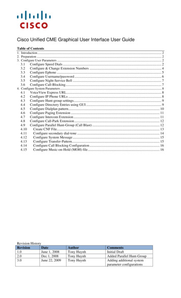
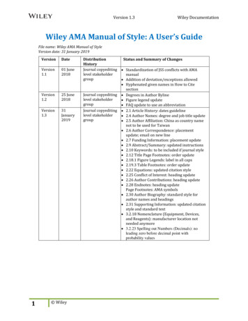
PICDEM-2 USER’S GUIDEChapter 1. Introduction1.1 WelcomeThank you for purchasing the PICDEM-2 demonstration board from MicrochipTechnology Incorporated. The PICDEM-2 is a simple board whichdemonstrates the capabilities of the 28- and 40-pin PIC16CXXX andPIC18CXXX devices.The PICDEM-2 can be used stand-alone with a programmed part, or with anemulator system, such as MPLAB -ICE. Sample programs are provided todemonstrate the unique features of the supported devices.The PICDEM-2 Kit comes with the following:1. PICDEM-2 Demonstration Board2. Sample devices3. Sample programs (3.5-inch disk)4. PICDEM-2 Demonstration Board User’s Guide (This document)If you are missing any part of the kit, please contact your nearest Microchipsales office, listed in the back of this publication, for help.3421Figure 1.1: PICDEM-2 Kit 2000 Microchip Technology Inc.DS30374C-page 1
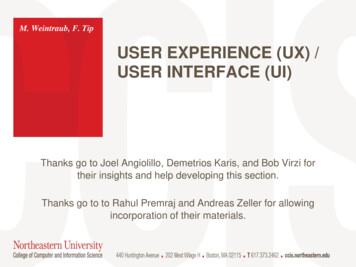
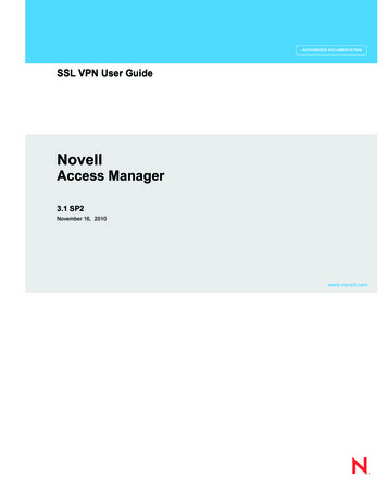
PICDEM-2 User’s Guide1.2 PICDEM-2 Demonstration BoardThe PICDEM-2 demonstration board has the following hardware features:1. 40- and 28-pin DIP sockets (Although 2 sockets are provided, only onedevice may be used at a time.)2. On-board 5V regulator for direct input from 9V, 100mA AC/DC walladapter or 9V battery, or hooks for a 5V, 100mA regulated DC supply.3. RS-232C socket and associated hardware for direct connection toRS-232C interface.4. Unpopulated holes for ACCESS.bus connector and associated hardware.5. 5K pot for devices with analog inputs.6. Three push button switches for external stimulus and RESET.7. Green power-on indicator LED.8. Eight red LEDs connected to PORTB for displaying 8-bit binary values.9. Jumper to disconnect LEDs from PORTB.10. Socket for “canned” crystal oscillator.11. Unpopulated holes provided for crystal connection.12. Unpopulated holes provided for Timer1 external crystal.13. Jumper to disconnect on-board RC oscillator (approximately 2MHz).14. 128 x 8 Serial EEPROM.15. LCD module header.16. Keyboard header.17. Prototype area for user hardware.27891511031711134141225166Figure 1.2: PICDEM-2 HardwareDS30374C-page 2 2000 Microchip Technology Inc.
Introduction1.3 Sample DevicesSeveral UV erasable devices are included. The device types may change, butwill generally include a 28-pin and 40-pin device.1.4 Sample ProgramsThe PICDEM-2 Kit includes a 3.5” disk with sample demonstration programson them. These programs may be used with the included sample device orwith an emulator system. The directory structure of the 3.5-inch disk is: PIC16CXXXtut.asma2d.asmiic.asm PIC18CXXXtut.asma2d.asmiic.asm1.5 PICDEM-2 User’s GuideThis document describes the PICDEM-2 demonstration board, and tutorialand demonstration software, to give the user a brief overview of thePIC16CXXX series of Microchip microcontrollers, as well as MPLAB IDE.Detailed information on individual microcontrollers may be found in thedevice’s respective data sheet. Detailed information on the emulation systemsmay be found in the respective emulator’s user’s guide.Chapter 1: Introduction – This chapter introduces the PICDEM-2 andprovides a brief description of the hardware.Chapter 2: Getting Started – This chapter goes through a basic step-by-stepprocess for getting your PICDEM-2 up and running as a stand-alone board orwith an emulator.Chapter 3: Tutorial – This chapter provides a detailed description of thetutorial program.Chapter 4: A/D Demo – This chapter provides a detailed description of thedemonstration program for the A/D module.Chapter 5: I2C/EEPROM Demo – This chapter provides a detaileddescription of the demonstration program for the SSP and MSSP modules inI2C mode. The program uses I2C to write to the serial EEPROM. 2000 Microchip Technology Inc.DS30374C-page 3
PICDEM-2 User’s GuideChapter 6: LCD Demo – This chapter provides a detailed description of thedemonstration program for interfacing a keypad to an LCD. A 4-bit and an8-bit interface program is provided.Chapter 7: USART Demo – This chapter provides a detailed description ofthe demonstration program for the USART module.Appendix A: Hardware Description: This appendix describes in detail thehardware of the PICDEM-2 board.1.6 Reference DocumentsReference Documents may be obtained by contacting your nearest Microchipsales office (listed in the back of this document) or by downloading via theMicrochip website (www.microchip.com). DS30374C-page 4Microcontroller Data Book (DS00158) or individual data sheetsMPLAB IDE, Simulator and Editor User’s Guide (DS51025)MPASM User’s Guide with MPLINK and MPLIB (DS33014)MPLAB PRO MATE User’s Guide (DS30082)PICSTART Plus User’s Guide (DS51028)MPLAB-ICE User’s Guide (DS51159)Microchip Third Party Guide (DS00104) 2000 Microchip Technology Inc.
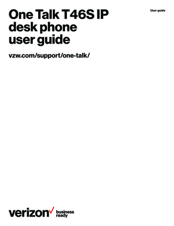
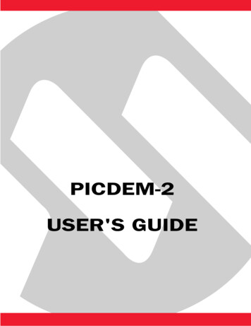
PICDEM-2 USER’S GUIDEChapter 2. Getting StartedThe PICDEM-2 may be used as a stand-alone board or with an emulator. Fora list of PICmicro 8-bit microcontroller-compatible emulators, please refer tothe Microchip Third Party Handbook or the Development Tool Ordering Guide.2.1 PICDEM-2 as a Stand-alone Board –Preprogrammed DeviceThe PICDEM-2 may be demonstrated immediately by following the stepslisted below: Make sure the pre-programmed sample device is in the appropriatesocket on the PICDEM-2 board. Make sure there are jumpers on J6 (to enable the LEDs) and J7 (toenable the on-board RC oscillator). Apply power to the PICDEM-2 (Figure 2.1). For information on acceptable power sources, see Appendix A. Press push-button S2 repeatedly to see the LEDs count up from 00h toFFh. Press push-button S1 to reset.Power Supply(not included)SampleDevicePICDEM-2 Demo BoardFigure 2.1: PICDEM-2 Stand-Alone 2000 Microchip Technology Inc.DS30374C-page 5
PICDEM-2 User’s Guide2.2 PICDEM-2 as a Stand-alone Board –Sample ProgramsTo demonstrate PICDEM-2 operation with one of the sample programs, thesample device will have to be erased and reprogrammed. Once the devicehas been reprogrammed: Make sure the sample device is in the appropriate socket on thePICDEM-2 board. Make sure there are jumpers on J6 (to enable the LEDs) and J7 (toenable the on-board RC oscillator). Apply power to the PICDEM-2 (Figure 2.1). For information on acceptable power sources, see Appendix A. Consult the appropriate chapter in this document for information on theexecution of each demo.2.2.1.Erasing the Sample DeviceTo erase an EPROM device: Remove any labels covering the device window. If you do not have awindowed device (Figure 2.2), you cannot reprogram it. A windowedversion of all EPROM devices may be ordered by requesting the JWpackage. Place the device in an Ultraviolet (UV) EPROM Eraser. The amount oftime required to completely erase a UV erasable device depends on:the wavelength of the light, its intensity, distance from UV source, andthe process technology of the device (how small are the memory cells). Verify that the device is blank (i.e., perform a blank check) beforeattempting to program it.Figure 2.2: PIC16C74 Windowed DeviceDS30374C-page 6 2000 Microchip Technology Inc.
Getting Started2.2.2.Reprogramming the Sample DeviceTo reprogram the erased sample device, the following will be necessary:1. Sample programs installed on the hard drive.The PICDEM-2 package includes a 3.5-inch disk which contains sampleprograms for all the processor types supported. Instructions on how toinstall the programs can be found in the readme file also on the disk.2. An assembler, such as MPASM available with MPLAB IDE.Sample programs may be used to program the sample device once theyhave been assembled. Microchip Technology’s MPLAB Integrated Development Environment includes an assembler (MPASM). However, otherassemblers may be used. For a list of PICmicro-compatible assemblers,please refer to the Microchip Third Party Handbook.3. A device programmer, such as PRO MATE II or PICSTART Plus.Once the sample program is in hex file format, a programmer may be usedto program a blank device. Microchip Technology’s PRO MATE II orPICSTART Plus programmers may be used. Both are compatible withMPLAB. However, other programmers may be used. For a list of PICmicrocompatible programmers, please refer to the Microchip Third Party Handbook.If the code protection bit(s) have not been programmed, the on-chip programmemory can be read out for verification purposes.Note: 2000 Microchip Technology Inc.Microchip does not recommend code protecting windoweddevices.DS30374C-page 7
PICDEM-2 User’s Guide2.3 PICDEM-2 Used with an In-Circuit EmulatorTo use PICDEM-2 with an in-circuit emulator, refer to the emulator’s user’sguide for instructions on how to connect, power up and configure the emulatorto the PICDEM-2.Configure the PICDEM-2 for the desired oscillator as described in Table 2.1.Refer to the emulator’s user’s guide for any oscillator configurationrequirements.Table: 2.1 OSCILLATOR SELECTIONOscillator Selection onPICDEM-2DS30374C-page 8Modification on PICDEM-2RCJ7 installed, Y2 empty,Y1 emptyCrystalJ7 removed, Y2 empty,crystal in Y1
Chapter 2. Getting Started 2.1 PICDEM-2 as a Stand-alone Board – Preprogrammed Device . 5 2.2 PICDEM-2 as a Stand-alone Board – Sample Programs 6 2.3 PICDEM-2 Used with an In-Circuit Emulator . 8 Chapter 3. Tutorials