Transcription
SECTION: C3.10.1403649 Cane Run Road . Louisville, KY 40211-1961877-244-9340 . Fax: 877-414-4316www.clarusenvironmental.com CL00560612SupersedesNewFusion Series Treatment SystemsOWNER'S MANUALThank you for choosing a Fusion Series Treatment System. High qualityworkmanship and easy maintenance have been incorporated into theFusion system. The system will provide years of trouble-free servicewhen maintained according to the manufacturer’s recommendations.Please read this manual in its entirety before using the Fusion , andfollow all instructions to ensure proper operation. Keep this manual forfuture reference along with other important onsite documents. Shouldfurther assistance be necessary, please contact Clarus Environmentalat 1-877-244-9340.1.DO NOT attempt to service the Fusion unit yourself. Contact yourauthorized maintenance provider for all service related issues.2.There are buried electrical cables and piping near and around theFusion . Please consult your authorized maintenance provider tolocate these utilities before excavation.3.DO NOT bury or cover the Fusion lids with soil or other debris.This is necessary to allow access for operation and maintenanceof the unit.Warning LabelsYou will find warning labels on the Fusion , riser lids, blower, and thealarm control panel. It is very important to follow the information onthese labels to ensure your safety. Please do not remove these labels.4.The Fusion blower must be unobstructed and vented forproper operation. Care must be taken that no grass clippings orother materials accumulate on or around the blower and blockventilation.5.DO NOT place heavy objects over the Fusion or drive heavyequipment over the Fusion , as damage may occur. Damage ofthis kind is not covered by the warranty.6.DO NOT plant trees within 15 feet (4.6 m) of the Fusion SeriesTreatment System.SEE LIST AT RIGHT FOR WARNINGSTABLE OF CONTENTSFusion Model: ZF-450 ZF-600 ZF-800Limited Warranty . . . . . . . . . . . . . . . . . . . . . . . . . . . . . . . . . . . . . . . 1Serial No.Installing ContractorStart Up . . . . . . . . . . . . . . . . . . . . . . . . . . . . . . . . . . . . . . . . . . . . . . 9Phone NumberBlower Timer Setting . . . . . . . . . . . . . . . . . . . . . . . . . . . . . . . . . . . 11Installation DateProcess Description . . . . . . . . . . . . . . . . . . . . . . . . . . . . . . . . . . . . 3System Components and Care . . . . . . . . . . . . . . . . . . . . . . . . . . . 4Excavation and Installation . . . . . . . . . . . . . . . . . . . . . . . . . . . . . . 6Operation and Maintenance . . . . . . . . . . . . . . . . . . . . . . . . . . . . . 12Aeration Chamber Cleaning . . . . . . . . . . . . . . . . . . . . . . . . . . . . . 14Fusion Pumping . . . . . . . . . . . . . . . . . . . . . . . . . . . . . . . . . . . . . 15Maintenance Provider’s NamePhone NumberTroubleshooting . . . . . . . . . . . . . . . . . . . . . . . . . . . . . . . . . . . . . . 16LIMITED WARRANTYManufacturer warrants, to the purchaser and subsequent owner duringthe warranty period, every new product to be free from defects in materialand workmanship under normal use and service, when properly used andmaintained, for a period of two years from date of purchase by the enduser. No allowance will be made for shipping charges, damages, labor orother charges that may occur due to product failure, repair or replacement.This warranty does not apply to and there shall be no warranty for anymaterial or product that has been disassembled without prior approval ofManufacturer, subjected to misuse, misapplication, neglect, alteration,accident or act of God; that has not been installed, operated or maintainedin accordance with Manufacturer's installation instructions; that has beenexposed to outside substances including but not limited to the following:sand, gravel, cement, mud, tar, hydrocarbons, hydrocarbon derivatives (oil,gasoline, solvents, etc.), or other abrasive or corrosive substances, washtowels or feminine sanitary products, etc. in all pumping applications. Thewarranty set out in the paragraph above is in lieu of all other warrantiesexpressed or implied; and we do not authorize any representative or otherperson to assume for us any other liability in connection with our products.Contact Manufacturer at, 3649 Cane Run Road, Louisville, Kentucky 40211,Attention: Customer Support Department to obtain any needed repair orreplacement of part(s) or additional information pertaining to our warranty.MANUFACTURER EXPRESSLY DISCLAIMS LIABILITY FORSPECIAL, CONSEQUENTIAL OR INCIDENTAL DAMAGES ORBREACH OF EXPRESSED OR IMPLIED WARRANTY; AND ANYIMPLIED WARRANTY OF FITNESS FOR A PARTICULAR PURPOSEAND OF MERCHANTABILITY SHALL BE LIMITED TO THE DURATIONOF THE EXPRESSED WARRANTY.Some states do not allow limitations on the duration of an implied warranty,so the above limitation may not apply to you. Some states do not allowthe exclusion or limitation of incidental or consequential damages, so theabove limitation or exclusion may not apply to you.This warranty gives you specific legal rights and you may also have otherrights which vary from state to state.The Fusion Series Treatment Systems represent a collaboration with Fuji Clean Co., Ltd. Copyright 2012. All rights reserved.
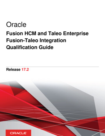
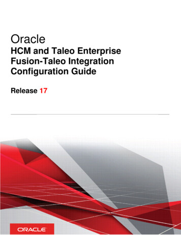
HOW A FUSION SERIES TREATMENT SYSTEM WORKSThe Fusion is simple in design, yet advanced in its wastewatertreatment ability. The design has been refined over many yearsof intense research and development in an effort to perfectthis superior treatment system. Fusion systems are 90% 95% efficient at treating wastewater. This is nearly twice aseffective as a traditional septic tank, which is approximately50% efficient. This high degree of treatment helps to protectboth your personal property and the environment.The Fusion utilizes a combination of anaerobic (withoutoxygen) and aerobic (with oxygen) biological processes to treatwastewater. As wastewater enters the Fusion , it is brokendown and becomes food for biological organisms operatingwithin the unit. The first chamber serves to separate greaseand large solids from the liquid. In the second chamber, plasticmedia with large surface areas are used to increase contactbetween water and beneficial bacteria to optimize treatment. Asmall linear air blower is used to move air (oxygen) into the thirdchamber for the aerobic process. The final effluent leaving thesystem will have been treated to secondary quality effluent andwill average *9 mg/L CBOD5 and 9mg/L TSS.* Based on NSF Standard 40 testing.Figure 1 - The following diagram will help you to better understand the process:Sludge Return LineRecirculation LineStorageChamberInlet Pipe4” PVCOutlet Pipe4” PVCSCH 40 (DN 100)SCH 40 (DN 100)Tank - CompressionMolded FiberReinforced PlasticAeration ChamberFloating/CirculatingFilter Media “Fluidized Bed”Invigorates aerobic bacteriaSedimentationChamber -Anaerobic Chamber -Separates bulk solidand grease wasteOrganisms adhere to fixed filmmedia and digest wasteFigure 2 - Schematic diagram of the Fusion Treatment SystemRe-circulationBaffle1Air-lift fluentInflowWall opening312Effluent4BaffleBaffle3BaffleAir-lift PumpSludge returnBackwashAeration6 “ (152 mm) stone or concrete padTop ViewRecirculationWall openingBackwash MechanismSide View Copyright 2012. All rights reserved.2
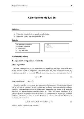
PROCESS DESCRIPTION1.Sedimentation ChamberThis chamber is designed to physically separate solidsfrom the incoming water. Scum is the floating materialand sludge is the material that has settled at the bottom.2.Anaerobic ChamberThis chamber contains a spherical skeleton-type filtermedia, 4.3 inch diameter (109 mm). Through bacterialgrowth processes on the surface of the filter media,biological anaerobic treatment thrives while suspendedsolids are captured. Furthermore, the microorganismsin this chamber convert nitrates in the recirculated waterreturning from the aerobic chamber to gaseous nitrogen.The gaseous nitrogen then escapes to the atmosphere.3.Aeration ChamberThe aeration chamber consists of an aerated uppersection and a filter media lower section. The chamber isfilled with hollow, cylindrical filter media 0.6 inch diameter(15 mm) and 0.55 inches long (14 mm). Biologicaltreatment takes place on the filter media surface.Aeration is continuous. Residual suspended solids arecaptured by the filter media circulating in this section.During normal operation, a recirculation line transferswater back to the sedimentation chamber by way of an airlift pump.The filter media in the aeration chamber are backwashedregularly (twice a day, 5 or 10 minute cycle) by thebackwash system located at the bottom of the chamber.The accumulated sludge is transferred by an air lift pumpback into the sedimentation chamber for further digestion.4.Storage ChamberThis chamber is designed to temporarily store treatedwater exiting the aeration chamber. This treated water isready for discharge.Figure 3 - Treatment Flow of the Fusion System.InflowSedimentation Chamber12Anaerobic ChamberBack-WashRecirculation3Aeration Chamber4Storage ChamberEffluentSYSTEM COMPONENTSThe complete wastewater treatment system will typically consist ofthe Fusion treatment components and a soil absorption field for finaldisposal of the liquid effluent. Some states or counties may requirethe addition of a septic tank before the Fusion to increase thesedimentation chamber capacity and retain more solids. Please seeFigure 11 for a typical Fusion system. Variations to the typical systemwill be made to suit your particular site and system design needs.Please contact your authorized Fusion installer or maintenanceprovider for further information about your system design.THE FUSION DUAL-PORT BLOWERThe Fusion treatment unit comes with an electronic, dualport blower designed specifically for use with this system. Theblower utilizes a linear motor and two diaphragms to generatethe air flow necessary to aerate and recirculate water within thesystem. This style of compressor is quieter and more efficientthan traditional rotary vane compressors. Once installed andadjusted, circuitry within the blower will automatically switch theunit from normal recirculation mode to backwash mode and backagain when appropriate. In the event of a power outage, theblower will stop, but a backup battery within the unit will retainthe correct time and backwash settings.NSF STANDARD 40, CLASS 1,CERTIFICATION MARKFigure 4 Certified toNSF/ANSIStandard 40Class 1PerformanceDesignation Copyright 2012. All rights reserved.3The NSF mark displayed herewill be on all NSF Standard40, Class 1 certified Fusion systems. The Fusion modelsZF-450, ZF-600 and ZF-800 willhave the mark displayed on thealarm panel. Systems not NSFStandard 40, Class 1 certified,will not display the mark.
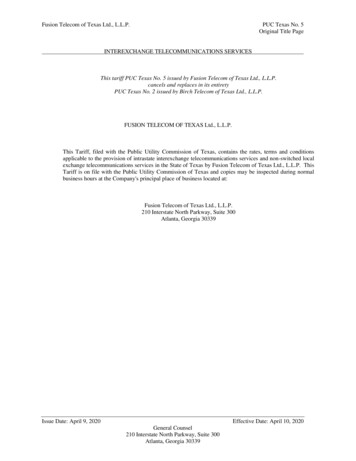
A dataplate similar to the one in Figure 5 is located on the blowerhousing and the alarm panel. There is important information aboutthe Fusion on the dataplate, such as the part number, modelnumber, serial number, and hydraulic capacity. Please make anote of this information for future reference or in case you shouldneed to contact your Fusion maintenance provider.F U S IO N TRE ATM EN T SY ST EMFigure 5 ZF ZF ZFThe contracting installer must mark the installed model numberon the dataplate, the blower housing and the alarm control panel.ALARM PANEL450450 GALLONS/DAY600600 GALLONS/DAY800800 GALLONS/DAYManufacturer:Clarus Environmental 3649 Cane Run RoadLouisville, KY 40211 1-877-244-9340 toll freeCOMPLETE BLOWER:P/N 019617BLOWER DIAPHRAGM:P/N 018848BLOWER FILTER:P/N 018849Figure 6RED BEACONWARNING!SILENCE/TESTSWITCHP/NYou may from time to time check the proper operation of thealarm panel by toggling the black switch on the side of the panelto “test”. The buzzer will sound and the red beacon will light aslong as you hold the switch in the test position. Release theswitch for normal operation.The Fusion system is designed to continuously operate automaticallywith little direct maintenance from the owner. Periodically, a check of theblower area is recommended to ensure no debris obstructs the ventilationor intake areas of the blower. Also, periodically test the control panelas outlined under the alarm panel section. The owner should closelymonitor the types and amounts of substances and products used. Wateruse should also be closely monitored to ensure proper operation of theFusion system. B LO WER SER V I CE P ART SThe Fusion comes with an alarm panel (see Figure 6) that isdesigned to activate an audible buzzer and red beacon light ontop of the panel if there is a drop in air pressure, if a high wateralarm condition occurs, or if the blower does not cycle betweenrecirculation and backwash modes within the preset time. (Note:Alarm panel can only function as long as there is electrical powersupplied to the panel)SYSTEM CARE Certified toNSF - ANSIStandard 40MFG.DATE: 09/07P/N 018860-BDATAPLATEBUZZERFUSIONDATAPLATEsk2649Figure 7 1 2 3 4 5 6 7 8TB2120 VACINCOMINGPOWERDISNFALARML1NGNDPeriodically, more extensive maintenance must be performed. Yourauthorized Fusion maintenance provider will oversee this service. Thename of the maintenance provider can be recorded on the front of thisdocument and should also be located on the alarm panel. For moreinformation see the Operation and Maintenance section of the manual.The owner should only perform minimal routine maintenance on the Fusion such as clearing debris from around blower housing (leaves, snow, andgrass clippings). The Fusion should also be protected from excessiveweight such as vehicular traffic. Trees and bushes should not be plantedin close proximity to the Fusion . The Fusion should be accessible tomaintenance personnel and the riser lids must never be buried.GND LUGHIGH WATERALARM*FOR ILLUSTRATION PURPOSES ONLY*REFER TO SCHEMATIC LOCATED INPANEL FOR INSTALLATIONBLOWERsk2933HIGH USE WATER DEVICESLEAKY FIXTURESThe draining of hot tubs and swimming pools into your Fusion systemcould cause hydraulic overloading and may reduce the treatmentefficiency. Please drain these devices to another location. Contactyour local regulatory authorities or authorized Fusion maintenanceprovider for more information. The use of large capacity single fill anddrain whirlpool bathtubs may also cause hydraulic overloading of yourFusion . Please limit the use of these types of tubs.It is very important to monitor all water fixtures in the home for leaksand drips and repair them immediately. Leaks can cause tremendouswater use and use may hydraulically overload your Fusion system andreduce its treatment efficiency. Excessive water use may also overloadyour soil absorption field and cause failure.INTERMITTENT USEThe Fusion system is designed to function even if wastewater doesFLOODINGnot enter it for extended periods of time. The power to the blowermust remain on during this time for the system to function properly.If flooding of the Fusion occurs and the blowerWeekend use will not harm the system as long as the blower is on.or the alarm panel is submerged, please disconnect power at theShould seasonal use require a complete shut down of the property,circuit breaker. DO NOT try to reconnect power to either the blowerthen it is recommended that the blower be turned off. It is importantor alarm panel once it has been submerged. Immediately contact yourto start up the system in advance of actual occupancy to allow forauthorized Fusion maintenance provider to inspect the Fusion , thenormal treatment to resume. Please contact your authorized Fusion blower, and the alarm panel. Your maintenance provider will repair ormaintenance provider for further information concerning shut down andreplace the components as needed.startup of the Fusion . You may also contact your maintenance providerfor the shut down and startup services. Copyright 2012. All rights reserved.4
HARMFUL SUBSTANCESINITIAL SERVICE POLICYThe Fusion is designed to treat household type waste andcan treat most common substances introduced into thesystem. However, certain harmful substances may reducethe efficiency or stop the treatment process by reducing ordestroying the beneficial bacterial populations responsible fortreatment. In general, if a chemical substance is consideredharmful to humans then it should also be considered harmfulto the Fusion treatment system. If you have any questionsconcerning the use of any of these substances, please contactyour Fusion maintenance provider. The introduction of anysubstance on the “Do Not List” into the Fusion will voidthe warranty.The Fusion models ZF-450, ZF-600, and ZF-800 (NSFStandard 40, Class 1 certified systems) have a two-year servicepolicy included in the initial purchase price. The service policy willinclude two inspections per year for a total of four inspections.During these inspections, numerous system checks andadjustments will be made to ensure proper operation. - THE DO NOT LIST DO NOT introduce the following substances into theFusion treatment system: Motor oil Antifreeze Brake fluid Paint Paint thinner Gasoline Solvents Pesticides Herbicides Strong disinfectants Strong caustic drain Toilet tankcleaners in excess disinfection chemicals Excess pharmeceuticals Chemicals & chemicalwasteNot Recommended: Trash and excess food products willlikely increase frequency of pumping.Trash Sanitary napkins andfeminine products Diapers Paper products such aspaper towels & baby wipes CondomsCat litterDental flossCigarette buttsPlastic/rubber productsFood Products Coffee filters and grounds Fruit and vegetable peels Meat products Garbage disposal waste Greases or lardsSeedsBonesEgg shellsLimited Use ProductsCertain products in small or moderate amounts should notdisrupt the Fusion treatment process. You should always usethe minimum quantities of these substances as recommendedby the manufacturer. Liquid laundry bleach only as needed per load Liquid laundry detergents without added bleach Liquid dishwashing detergents Household cleanersEFFLUENT QUALITYFusion Series systems are compact, efficient, and designed tobe installed in a typical residential/light commercial environment.The final effluent leaving the system will typically be treated to thesecondary quality strength of *9 mg/L CBOD 5 and 9 mg/L TSS. * Based on NSF/ANSI Standard 40 testing.WATER SOFTENERSIf water softners are present in the home, Clarus Environmentalrecommends the use of water and salt conservative modelsthat are installed and operated correctly. If you have questionsabout softeners, contact the Water Quality Association atwww.wqa.org. Contact factory for installation details. EXTENDED MAINTENANCE POLICYAn extended maintenance policy is available for purchase fromyour authorized Fusion distributor. The extended maintenancepolicy will include the same system checks, schedule, andadjustments as the initial maintenance policy. Please contactyour Fusion distributor or maintenance provider for furtherinformation regarding the extended maintenance policy.AUTHORIZED MAINTENANCE PROVIDERYour authorized maintenance provider will perform many systemchecks and adjustments as needed during the maintenanceinspection. Two inspections per year will be made for a total of fourinspections during the initial service policy. Please see the Operationand Maintenance section of this manual for further details.Should there be any operational deficiencies with your Fusion ,the maintenance provider will notify the owner in writing when thedeficiencies will be corrected. If the maintenance provider doesnot correct the deficiencies or the service calls are not completed,please contact Clarus Environmental at 1-877-244-9340.INSPECTION AND MAINTENANCE FREQUENCYFusion Series systems are to be inspected and maintainedevery six months under normal usage. The inspection andmaintenance are only to be performed by personnel trained andauthorized by Clarus Environmental. A Maintenance & ServiceReport (CL0059) is to be completed for each inspection andmaintenance visit.ALARM CONDITIONIf an alarm condition occurs, please check the air intake areaaround the blower and make sure no debris blocks the blowerintake. Remove the air filter cap by removing the screw fromthe cap and then pulling on the sides of the top of the blower.Remove the foam filter and gently tap against your other hand.If it is very clogged wash it in warm, soapy water and dry wellbefore replacing. Reassemble filter and cap on top of blower.Do not attempt to remove the blower housing or any otherparts from the blower. If the blower is operating properly, theremay be a high water condition within the Fusion . It may benecessary to discontinue water use until the alarm conditionhas been resolved. If the buzzer continues to sound or thered light stays on, please contact your authorized Fusion maintenance provider. The buzzer may be silenced by togglingthe black switch on the side of the alarm panel to “silence”.The red beacon light will remain on until the problem has beenresolved.POWER OUTAGEShould you experience a power outage, the blower will notoperate and air (oxygen) will not be supplied to the Fusion .If the blower is off for more than 24 hours, the lack of freshair will cause the treatment efficiency to decrease. During apower outage, the Fusion will still allow effluent to flow, andwill not create a backup in the home. You may, however,have a pump or dose tank with a pump on the outlet of theFusion , which requires power to pump the effluent to thesoil absorption field. If you have a system such as this,please be aware of this condition and conserve wateraccordingly. Copyright 2012. All rights reserved.5
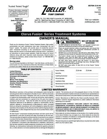
EXCAVATION AND INSTALLATION1.2.3.4.5.Excavate an area large enough for the Fusion Series unit to be installed. See Figure 8 and Table 3 for the actual dimensionsof the unit. Excavation dimensions are calculated by adding 12-18" (305-457 mm) to the length and width of the Fusion . Thiswill allow sufficient room for proper backfilling.Construct a 6" (152 mm) thick stone pad of either 1/4" - 1/2" (6-13 mm) diameter stone or concrete pad and level to within 1/8" (3 mm).If the unit is not level, it will cause uneven water flow as well as unbalanced aeration, which will result inpoor performance.Gently lift the unit at all four lifting points with a harness and install it on leveled stone pad (Figure 9).Check unit to make certain it is level by placing a level at several locations on the riser. (riser covers removed) (Figure 9).BACKFILLINGCOLD WEATHER INSTALLATION1.If groundwater is present, anti-flotation measures must beused to stabilize the unit prior to backfilling. Please followthe procedures in the Anti-flotation section to properlyanchor the Fusion .2.Fill the unit with clean water to the normal operating depthprior to backfilling. Partition walls between chambers arewater-tight and will fill in succession beginning on the inletside of the unit. Therefore, it is best to alternate chamberswhen filling with water so the unit remains level. Check forleakage around the unit.3.4.If necessary, install riser extensions on the adapter ringsprior to backfilling. See Table 1 for number and size ofaccess opennings. Riser extensions are available fordeeper burial. Make certain risers are sealed properly andwatertight.Apply two beads of silicone fully aroundeach riser section prior to securing with supplied screws.5.Install riser covers.6.Backfill with good quality granular soil around the unit that isfree of organic matter, rock, stone, tree roots, or other debristhat could damage the unit.7.Tamp soil around perimeter of the unit as it is backfilled tostabilize the unit and to reduce settling.8.Finalize backfill with a mounded contour so that surfacewater is shed away from the unit. Under no circumstancesshould surface water be allowed to accumulate around unit.9.MAXIMUM soil burial depth over the unitis 36 inches (914 mm).Table 1number and size of access openings in fusion seriesZF-450ZF-600ZF-80020" (51 cm) Diameter01124" (61 cm) Diameter222When installing Fusion in cold climates, the designer shouldspecify insulated lids and risers from the factory. These areavailable as an option to the standard lids and risers. In addition,the blower must be protected from snow drifts by installing iteither inside a garage, home, basement, crawlspace or riser. Ifinstalled in a riser, the blower must be protected from inundationand must have a vent pipe installed to above the maximumsnow depth with a 180 degree angle at the end to prevent snowand water entry. Also, the top and sides of the Fusion must beinsulated with insulation sheeting or other means to provide aminimum insulation value of R-8. Please contact the factory forfurther information.ANTI-FLOTATION PROCEDURESIt is necessary to anchor the Fusion in high ground waterconditions to prevent flotation. If groundwater rises above therock or concrete pad that the Fusion sits on, anchoring isrequired. Please consult a design engineer, soil scientist or otherqualified individual to determine high groundwater conditions.1. Follow the procedures outlined in the Excavation andInstallation Section items 1-5 to properly prepare and levelthe Fusion excavation.2. Follow the procedures outlined in the Backfilling Sectionitems 1-4 to properly fill the Fusion with water and addrisers if needed.3. Refer to Figure 10, Anchoring Schematic to determinethe minimum amount of backfill to be placed around theFusion in the excavation. Tamp the fill to prevent settling.4. Refer to Table 3, Concrete Anchoring Dimensions todetermine the amount of concrete needed for the concreteanchor collar that is poured around the entire circumferenceof the Fusion . Pour concrete to the specified dimensionsto fully engage the mid-seam of the Fusion , which willanchor it once the concrete cures. Make certain to pourthe concrete in a manor to minimize trapped air withinthe concrete. Agitating or lightly mixing the concrete witha metal rod or other similar device once poured will helprelease trapped air.5. Allow the concrete to harden before final backfilling.6. Complete the procedures outlined in the Backfilling Section,items 5-8.Figure 8- DimensionsTable 2OUTLETINLETFUSION DIMENSIONS SYSTEMLWHIEFusion 4507'-1" (2.2 m)3'-8" (1.1 m)5'-2" (1.6 m)4'-4" (1.3 m)3'-10" (1.2 m)Fusion 6008' (2.4 m)4'-1" (1.2 m)5'-6" (1.7 m)4'-8" (1.4 m)4'-2" (1.3 m)Fusion 8008'-3" (2.5 m)4'-8" (1.4 m)6'-2" (1.9 m)5'-4" (1.6 m)4'-10" (1.5 m) WEHNOTES:I1) DIMENSIONS "I" AND "E" ARE TO THE BOTTOMOF THE INLET/OUTLET PIPE.2) THE OVERALL HEIGHT DIMENSION "H" IS TO THETOP OF THE NARROW ADAPTER RING, NOT THE RISER LID.3) A RISER COVER COMES STANDARD. ADDITIONAL RISERS AREPURCHASED SEPERATELY. Copyright 2012. All rights reserved.6Lsk2624
Figure 9, Lifting & PositioningFigure 10, Concrete AnchoringLESS THAN 60 60 4-POINTLIFTINGCONCRETE ANCHORCOLLARLIFTINGHOOKMIN. REQUIREDBACKFILLLIFTINGLEVEL ACROSS TOP OF UNITUNIT LINGsk2931Table 2 - Concrete Anchoring DimensionsModelNo CoverW(ft)ZF-450 1' - 4"ZF-600 1' - 6"ZF-800 1' - 8"ModelH(ft)(ft)ZF-450 1' - 0"ZF-600 1' - 1"ZF-800 1' - 3"6" CoverWH(ft3)(CY)(ft)(ft)2' - 0"7231' - 2"2' - 0"2' - 0"91109341' - 4"1' - 7"24" CoverWConcrete VolumeH(ft)2' - 0"2' - 0"2' - 0"Concrete Volume12" CoverWHConcrete Volume(ft3)(CY)(ft)(ft)2' - 0"6231' - 1"2' - 0"562' - 0"2' - 0"79102341' - 3"1' - 5"2' - 0"2' - 0"739030" CoverWConcrete VolumeH(ft3)(CY)(ft)(ft)5162782331' - 0"1' - 1"1' - 2"2' - 0"2' - 0"2' - 0"Concrete Volume36" CoverWH(ft3)(CY)(ft)(ft)5162722331' - 0"1' - 0"1' - 1"2' - 0"2' - 0"2' - 0" Copyright 2012. All rights reserved.7(ft3) (CY)18" CoverWHConcrete Volume(ft)(ft)(ft3)(CY)31' - 0"2' - 0"512341' - 2"1' - 4"2' - 0"2' - 0"688434Concrete Volume(ft3)(CY)515766233
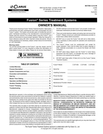
Figure 11, Typical Fusion LayoutFUSION CONTROL PANELWARNING!RISER AND LIDBLOWERTO DRAIN FIELDCLEAN -OUTSEWER LINEAIR LINEOPTIONAL SEPTIC TANK INSTALLATIONMAY BE REQUIRED BY LOCALOR STATE REGULATIONSFUSIONsk2650BLOWER INSTALLATION AND PLACEMENT1. The blower must be connected to a grounded, metallic, permanent wiring system, oran equipment-grounding terminal or lead on the product.2. Place the blower where it is easily accessible for maintenance and inspection.3. Install the blower in an area where it will be protected from damage and inundation.Also make certain the location has good ventilation.RISER CONFIGURATION4. Install the blower on a foundation that is level and solid.5. Excavate trenches for two air lines from blower to the unit.6. Install two separate 1/2" (13 mm) air lines from the blower to the unit. Length of pipingmust be less than 17' (5 m). If distances from 17' (5 m) to 33' (10 m) are required,use 3/4" (19 mm) diameter piping (Figure 12). If longer air lines are needed, consultthe factory.DECORATIVE ROCK CONFIGURATION7. The blower is provided with two discharge ports. The blower label is color-coded with theaeration outlet port being BLUE and the backwash outlet port being RED (Figure 12).8. The air port inlets on the Fusion are also color-coded, BLUE for aeration and REDfor backwash (Figure12).9. Attach the barbed end of each PVC tee (included in the blower box) to the blowerusing the rubber elbows (Figure 12).INTERIOR CONFIGURATION10. Attach the small diameter black air tubing (included in the blower box) to barbed fittingon PVC tee. Black air tubing and blower power cord should be routed to the alarmpanel through conduit. Attach the two black air tubing lines to the two air pressuresensor barbed fittings in the alarm panel (Figure 12).RED AIRLINEBLOWERPOWERCORD11. Connect the remaining end of each PVC tee to the airlines installed in Step 6.AIR LINETO PANELADAPTER!Figure 12CONDUIT TOPANELRED AIRLINEBLUE AIRLINEAIR LINETO PANELRUBBERELBOWSBLUE AIRLINETO PREVENT ELECTRICAL SHOCK FROMBACK-SIPH
The Fusion Series Treatment Systems represent a collaboration with Fuji Clean Co., Ltd. Fusion Series Treatment Systems SECTION: C3.10.140 CL0056 0612 Supersedes New 3649 Cane Run Road . Louisville, KY 40211-1961 877-244 -9340 . Fax: 877 414-4316 www.clarusenvironmental.com OWNER'S MANUAL