Transcription
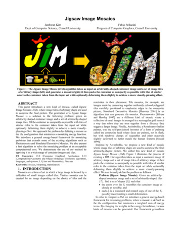
Jigsaw Image MosaicsJunhwan KimDept. of Computer Science, Cornell UniversityFabio PellaciniProgram of Computer Graphics, Cornell UniversityFigure 1: The Jigsaw Image Mosaic (JIM) algorithm takes as input an arbitrarily-shaped container image and a set of image tilesof arbitrary shape (left) and generates a mosaic (right); it then packs the container as compactly as possible with tiles of similarcolor to the container taken from the input set while optionally deforming them slightly to achieve a more visually-pleasing effect.ABSTRACTThis paper introduces a new kind of mosaic, called JigsawImage Mosaic (JIM), where image tiles of arbitrary shape are usedto compose the final picture. The generation of a Jigsaw ImageMosaic is a solution to the following problem: given anarbitrarily-shaped container image and a set of arbitrarily-shapedimage tiles, fill the container as compactly as possible with tiles ofsimilar color to the container taken from the input set whileoptionally deforming them slightly to achieve a more visuallypleasing effect. We approach the problem by defining a mosaic asthe tile configuration that minimizes a mosaicing energy function.We introduce a general energy-based framework for mosaicingproblems that extends some of the existing algorithms such asPhotomosaics and Simulated Decorative Mosaics. We also presenta fast algorithm to solve the mosaicing problem at an acceptablecomputational cost. We demonstrate the use of our method byapplying it to a wide range of container images and tiles.CR Categories: I.3.8 [Computer Graphics]: Application; I.3.5[Computational Geometry and Object Modeling]: Geometric algorithms,languages, and systems; J.5 [Arts and Humanities]: Fine artsKeywords: Mosaics, Morphing, Optimization1. INTRODUCTIONMosaics are a form of art in which a large image is formed by acollection of small images called tiles. Various mosaics can becreated for an image depending on the choice of tiles and therestriction in their placement. Tile mosaics, for example, areimages made by cementing together uniformly colored polygonaltiles carefully positioned to emphasize edges in the compositepicture; Simulated Decorative Mosaics [Hausner 2001] is analgorithm that can generate tile mosaics. Photomosaics [Silversand Hawley 1997] are a different kind of mosaic where acollection of small images is arranged in a rectangular grid in sucha way that when they are seen together from a distance theysuggest a larger image. Finally, Arcimboldo, a Renaissance Italianpainter, was the self-proclaimed inventor of a form of paintingcalled the composite head where faces are painted, not in flesh,but with rendered clumps of vegetables and other materialsslightly deformed to better match the human features [Strand1999].Inspired by Arcimboldo, we propose a new kind of mosaicwhere image tiles of arbitrary shape are used to compose the finalarbitrarily-shaped picture. We called this new kind of mosaicJigsaw Image Mosaic (JIM). Figure 1 illustrates the process ofcreating a JIM. Our algorithm takes as input a container image ofarbitrary shape and a set of image tiles of arbitrary shape; it thenpacks the container as compactly as possible with tiles of similarcolor to the container taken from the input set while optionallydeforming them slightly to achieve a more visually-pleasingeffect. We can formally define the problem as follows:Problem (Jigsaw Image Mosaic): Given an arbitrarilyshaped container image and a set of arbitrarily-shaped tiles{Ti}, find a set of shapes {Sj} such that the union over the Sj resembles the container image asclosely as possible; and each Sj is a translated and rotated copy of one of the Ti,possibly incorporating a small deformation.In order to compute a JIM, we introduce a general energy-basedframework for mosaicing problems, where a mosaic is defined asthe tile configuration that minimizes a weighted sum of energyterms. By changing the weights in the energy formulation, variouskinds of mosaics can be generated. Our framework generalizes
a) Input imagec) Jigsaw Image Mosaic (JIM)d) Photomosaice) Simulated Decorative Mosaicroughly 400 tilesfrom a database of 900 tilesroughly 400 tilesfrom a database of 1100 photographsroughly 400 tilesb) JIM tile contoursFigure 2: Comparison of different mosaicing algorithms.some of the existing mosaicing techniques previously presented inthe computer graphics literature such as Photomosaics [Silversand Hawley 1997] and Simulated Decorative Mosaics [Hausner2001]. A comparison of the images obtained by the threealgorithms is presented in Figure 2. As with Photomosaics, ouralgorithm uses tiles containing smaller images. As in SimulatedDecorative Mosaics, the Jigsaw Image Mosaics maintainimportant edges found in the container image; while the firstalgorithm does so by reorienting the tiles, our approach usesoriented tiles of the best-fitting shape as shown, for example, bythe wedge-shaped tiles used in the sharp corners of the drops inFigure 2b and Figure 2c. The two algorithms use a segmentationof the original image in order to specify important edges.Our framework has three major advantages. First, a user caneasily control the result image by changing the weights in theenergy formulation. Second, we can introduce new mosaicinggeneration rules by introducing additional energy terms in theenergy formulation. Finally, the mosaic generation and tilepreparation is completely automatic requiring no userintervention.Since the Jigsaw Image Mosaic problem can be cast as aninstance of an energy minimization problem, various algorithmssuch as simulated annealing could be employed to find a solution.Unfortunately, due to its high dimensional search space, most ofthe standard minimization techniques would demand too manyresources to be run. This paper also presents a fast minimizationalgorithm tailored to solve the generalized mosaicing problem.We believe that the two major contributions of this paper are an energy-based framework for the mosaicing problem whichgeneralizes on known algorithms an energy-minimization algorithm that solves the mosaicingproblem at an acceptable computational costAlso, since our framework presents a general solution to ‘soft’packing problems, where small deformations are acceptable, ourframework can be applied to feature-based texture synthesis andto various instances of product manufacturing. Mosaics are justone application.The rest of this paper is organized as follows: Section 2summarizes related work. In Section 3, we describe how toautomatically prepare the required inputs. Sections 4 and 5address the energy minimization framework of the mosaicingproblem, and the basic algorithm for the framework respectively.Section 6 presents optimization techniques on top of the basicalgorithm. We present our results in Section 7, and close withdiscussion and future work in Section 8.2. RELATED WORKIn the computer graphics literature, the works most closelyrelated to our approach are the various mosaicing algorithms thatcan be categorized by the choice of tiles and the restriction ontheir placement. Photomosaics [Finkelstein and Range 1998;Silvers and Hawley 1997] are a collection of small imagesarranged in a rectangular grid in such a way that when they areviewed together from a distance they suggest a larger image (e.g.Figure 2d). For each rectangular block of pixels in the inputimage, the photomosaic algorithm searches a large database oftiles to find the one that most closely resembles the original block.The algorithm gives impressive results using only small resources,but unfortunately it is limited to square tiles on a rectangular grid.Simulated Decorative Mosaic [Hausner 2001] approaches theproblem of aligning square tiles with varying orientations topreserve input image edges while maximizing the area covered bythe colored tiles (e.g. Figure 2e). Our algorithm resembles thatapproach since it tries to maintain edges in the input image whilemaximizing coverage. Unfortunately, since we use tiles ofdifferent shapes, we cannot directly apply the SimulatedDecorative Mosaic method for finding low-energy configurations.Our technique can compute the same results as these twoalgorithms, although its generality exacts a penalty in speed.Kaplan and Salesin [2000] presented a solution to the“Escherization" problem that finds a regular tiling using a closedfigure that is as similar as possible to the original figure. Theirwork resembles our approach in that they slightly distort theoriginal tile if necessary, but is different in that they seek regulartilings whereas we allow small gaps and overlaps. Haeberli [1990]randomly chose the tile positions, found the voronoi diagram ofthese positions, and filled each voronoi region with a colorsampled from the underlying image. While his approachtessellates the main image using tiles of different shapes andcompletely arbitrary placements, the shapes are arbitrary and maynot fit any of the given input tiles as required in our formulation.Another body of work related to our approach is the packingproblem. The packing problem has been extensively studied inoperations research and computational geometry with applicationto a broad spectrum of layout problems, such as for cloth, leatherand glass. Since the packing problem is NP-hard [Milenkovic1999], numerous heuristics have been developed: boundarymatching, database driven layout, or leftmost placement policy(See [Dowsland and Dowsland 1995] for an extensive survey).Recent work of Milenkovic and his colleagues [1999] combined
ContainerTrying 1st tile Trying 2nd tile Trying 3rd tile Trying 4th tile Trying 5th tile Legend high colorenergy Æ discard high gapenergy Æ discard high overlapenergy Æ discard high deformationenergy Æ discard lowest energy ÆAcceptContainer to befilledContainer filledTilesColor mismatchGap regionOverlap regionShape mismatchAccepted tileFigure 3: Illustration of mosaicing energy terms.computational geometry and mathematical programming fordense packing of polygons. Their approach applied to markerlayout problems achieves packing efficiencies comparable tothose of human experts. Our problem differs from the standardpacking problem in that our aim is not to achieve maximumdensity packing, but to reach aesthetically pleasing packing.Inspired by Arcimboldo, we allow a small user-specifieddeformation of the tiles when necessary, which is not allowed inthe standard packing problem formulation.3. PREPARING INPUTSThe JIM algorithm takes as input a container image of arbitraryshape and a set of tiles of arbitrary shape. The shape of tiles andcontainer is represented by a polygon. Since we require a fairlyhigh number of tiles, we need to be able to extract the shape of thetiles directly from the images themselves. We do so using activecontours [Kass et al. 1987]. All of the 900 tiles used to generatethe images in this paper are segmented completely automaticallyfrom clip art harvested from the Web. Active contours are alsoused to extract the container shape.Hausner [2001] showed the importance of preserving importantedges in the input image when generating a mosaic. Following hisapproach, we segment the input image to generate a set of disjointarbitrarily-shaped containers. Since we preserve the edge of eachcontainer, the final composite will preserve the important edgeson the input image. Figure 2c shows this behavior. Within eachpart of the segmentation, the algorithm runs independently. Byallowing the user to input arbitrary segmentations, we can alsointroduce edges that are not present in the input image, but areimportant to maintain for the user.4. MOSAICING FRAMEWORK4.1 Problem formalizationIn order to achieve user controllable and extensible framework,we cast the problem of generating a mosaic in an energyminimization framework. We define a “tile configuration” as asubset of the input tiles with repetition, along with their associatedtransformations (translation, rotation, deformation). We say that atile configuration is a Jigsaw Image Mosaic when it minimizes theenergy E defined asE w C E C w G E G wO E O w D E D .(1)The energy is a weighted sum of various terms. Figure 3illustrates the behaviors of each of these energy terms in a simpleexample. The color energy term EC penalizes configurations thatdo not maintain the color of the input image. The gap energy termEG penalizes configurations that have too much empty space in thefinal image, called gap, while a big overlap between tiles giveslarge overlap energy EO. Finally, the deformation energy EDpenalizes configurations where tiles are highly deformed.Inspired by Arcimboldo, we allow small deformations for eachtile since we may not find a configuration where gaps or overlapsare small enough to achieve a pleasing visual effect. This is morelikely to happen for smaller tile databases. Since collecting a largenumber of tiles may be a long process, we believe that allowingthe user to specify the amount of deformation necessary makes thealgorithm more usable.In order to compute a Photomosaic in our formulation, we cansimply restrict the tile database to rectangular tiles and set theweights for gap, overlap and deformation to infinity. To computea Simulated Decorative Mosaic, we restrict the database to squaretiles with uniform color, where the colors are chosen from thepalette of the input image, and segment the container to preserveedges. We then set the deformation weight to infinity and a veryhigh overlap weight (note that Simulated Decorative Mosaicsresults have sometimes very small overlaps [Hausner 2001]) andmoderately high gap weight.We believe that our formulation is fairly intuitive to use, sincethe user can easily adjust the weights in the energy function toobtain different results. It is also easily extensible, since we canadd new energy terms in order to introduce additional rules forimage generation.4.2 Energy terms evaluationThe color energy EC is estimated by taking the average of the L2differences of the colors of the final image and the input containerat random locations on the surface of the container. We evaluatethis term for each tile separately to ensure a good sampling of thetile area.We evaluate gap EG and overlap EO energies using the springenergy formulation as originally employed to prevent bodies inresting contact from penetrating in rigid body simulations [Mooreand Wilhelms 1988]. More specifically, each vertex of a tile isattached with a spring to the nearest edge of the other tiles or thecontainer. If the signed distance d between the vertex and theanchor is positive, i.e. there is a gap between them, we add d2/2 toEG. On the other hand, if d is negative, i.e. the vertex penetratesthe nearest edge, we add d2/2 to EO.The deformation energy ED is the sum of the deformationenergies for each tile, which measures the difference in shapebetween the deformed tile and the original one. We evaluate ED ina similar way to the active contour model, given by122E D ik 1 01α Di′′( s ) Ti′′( s ) β Di′′′( s ) Ti′′(′ s ) ds , (2)2where Ti(s) and Di(s) are the original shape and the deformedshape of the i-th tile in the current solution, parameterized by s [0,1]. The first term and the second term inside the integralmeasure the difference between the original tile and the deformedtile with respect to the stretching and flexing respectively, where αand β are sensitivity parameters. Among numerous shape metricssuch as [Arkin et al. 1991], we choose the above one, since itprovides good results in our case and it is easily integrated in ouralgorithm.
a) Initial containerimageb) Tile contours aftertile placementPhase 1:Placing tilesc) Tile contours aftertile refinementPhase 2:Refining tilesd) Final JigsawImage MosaicPhase 3:Adjusting imagesFigure 4: Jigsaw Image Mosaic algorithm phases.5. BASIC MOSAICING ALGORITHM5.1 OverviewTo efficiently compute a Jigsaw Image Mosaic, we propose aneffective algorithm organized in three phases shown in Figure 4.In the first phase, we choose and roughly place the tiles, ignoringdeformation. In the second phase, we refine the placement of eachtile and deform them if necessary. Finally in the third phase, weassemble the final mosaic by placing each tile in its position andwarping each image to its final deformed shape using the imagewarping technique presented in [Arad et al. 1994]. Intuitively, thisthree-phase approach works in our case because the deformationswe allow are always much smaller than the smallest tile in thedatabase.5.2 PackingThe first phase of the algorithm finds an approximately goodconfiguration ignoring the deformation term, i.e. the configurationthat minimizes the gap and overlaps in the image whilemaintaining the color, as measured byE w C E C w G E G wO E O .(3)To do so, we use a best first search [Russell and Norvig 1994].Our algorithm places one tile at a time. For each new tile to place,we find a roughly suitable position in the container. We thensearch the database to determine which tile we should use, anddetermine the exact position and orientation of the tile in such away that the tile is maximally aligned to the boundary ofcontainer, i.e., E in Equation 3 is minimized. This is a typicalregistration problem except that we register the tile to a part of thecontainer, rather than the container itself. We will explain in moredetail in Section 6 how to efficiently find a suitable spot using acentroidal voronoi diagram (CVD) [Lloyd 1982] and how tosearch the database using geometric hashing.After we place a tile, a new container is computed bysubtracting the tile shape from the original container, as shown inFigure 5. The new container is used to place the next tile.We keep placing tiles until either the tiles completely fill out thecontainer or we cannot find a suitable tile to fill a container. If thishappens, we backtrack to the configuration that has minimalenergy so far. Figure 6 illustrates the algorithm sequence.aInitialcontainerTilebContainer withplaced tile5.3 RefinementEven after finding the best possible tile arrangement, too muchgap or overlap may remain and be aesthetically displeasing,especially when using a small number of tiles. Sometimes we canobtain a better looking result by slightly deforming the tiles toreduce gaps and overlaps significantly, as long as the deformationdoes not alter the original tile too much. While this generallyproduces better looking images, the user has the option to definethe amount or skip deformation.The refinement phase of our approach solves this issue bydeforming the tiles obtained from the packing stage, whilebalancing between maintaining the original tile shape as closely aspossible and minimizing the gap, overlap and color differences(i.e. minimizing the full energy equation). We compute the finalconfiguration using a set of active contours [Kass et al. 1987]interacting with each other. Intuitively, each vertex of a contour issubject to forces that tend to maintain the contour’s original shapeand to repulse two contours if they penetrate, or attract them ifthere is gap between them. The tile configuration that minimizesE in Equation 1 must satisfy the following euler equation:wC E C wG E G wO E O w D E D 0 . (4) EC is close to zero for our case since the deformations are muchsmaller than the smallest tile. For each vertex, EG 2d n if thevertex is in a gap (0 otherwise), where n is the unit vectorperpendicular to the nearest edge, d is the signed distance to thenearest edge. EO 2d n if the vertex penetrates another tile (0otherwise). EO makes the tile shrink if it is too big while EGexpands it if too small. The deformation term can be computed bydifferentiating Equation 2 for each vertex:(5) E D α (Di′′( s ) Ti′′( s ) ) β (Di′′′( s ) Ti′′(′s ) ) .aContainercPlace 1st tilebAvailable TilesCannot place nextBacktrackcContainer fornext iterationFigure 5: Container update.Try again 1st tilePlace nextFigure 6: Tile placement.Done
Notice that Equation 5 is exactly the same energy formulationused for standard snakes but the ‘relaxed’ state is defined as theoriginal tile shape rather than a simple straight line. Also, externalforces are determined not by an image (as in the standard snake),but by gap and overlap between tiles and with the container. Thesolution to the above equation can still be found by solving thediscrete system iteratively [Amini 1990]. Figure 7 shows theevolution from the original tiles to the deformed ones.6. ALGORITHM OPTIMIZATIONSIn the previous section, we presented the basic algorithm for tileplacement. A naïve implementation would be too resourcedemanding so we present several optimization techniques in thissection. The time complexity of the algorithm is roughly given byO (Vtile N tile Vcontainer N tileInContainer (1 b )) .(6)where Vtile is the number of vertices per tile, Ntile is the number oftiles in the database, Vcontainer is the number of vertices incontainer, NtileInContainer is the number of tiles in the container, andb is the overhead due to branching in the search tree(backtracking). In the following subsections we will introduceoptimization for each of the factors in Equation 6.6.1 Placing a tileWhen placing a tile in a container of arbitrary shape, it would beprohibitive to try every possible location. As we mentionedbefore, we update the container after placing every tile. In order toreduce the branching overhead b, we try those locations that aremost likely to make the container shape easier to fill afterupdating. Unfortunately this depends on which tile we place.Nevertheless, we can guess how the container would look after weput an “average” tile. A container will be easier to fill if it doesnot have a protrusion and is as convex as possible.Before placing a new tile, we construct a CVD, where each sitehas an area roughly equal to the average size of tiles (a similartechnique has been previously used in [Hausner 2001]). We thenselect a random site among the ones that have the least number ofneighbors, thus making the container as easy as possible to fill.Figure 8 shows the selection process. Notice that placing one tileat a time allows us to handle tiles with different sizes. Figure 2c,for instance, contains tiles that differ in size by 7 times.6.2 Branch-and-bound with look-aheadEvery time we cannot find a suitable tile to fill a container, weneed to backtrack to the configuration that has minimal energy sofar. To reduce this branching overhead b, we use a look-aheadtechnique [Russell and Norvig 1994]. When placing a new tile, wepenalize tiles that will make it harder to fill the container in thenext iteration. To do this we add a term to the energy formulationthat takes into account how the container will look after tileplacement. Thus, the energy in Equation 3 becomes:(7)E wG EG wO EO wC EC wLA E LA .The container shape term advocates for containers with a smallarea and short circumference, or(8)E LA wA area (1 wA ) length 2 ,where area is the container’s area, length is its boundary length,a) Initialcontoursb) Intermediatecontoursc) ConvergedcontoursLegendCVD connected graphCVD cellsSelected position:only two neighborsin the CVD graphFigure 8: Selecting a tile position by CVD.and wA controls the weight of area in relation to the weight oflength. Adding the container shape term in the energy evaluationprevents the algorithm from placing a tile that fits well but thatleads to a harder-to-fill updated container.6.3 Container cleanupAfter we place a tile in a container, we update the container bysubtracting the tile from the container. However, the newcontainer can be very jagged, or even have disjoint regions. Ifthese fragments are shallower than the shallowest tile, we know itcan never be filled with any existing tile. In that case, it is safe toseparate those fragments and consider them as a gap. This cleanupprocess reduces the running time by cutting the number of verticesin the container Vcontainer. It also reduces the branching overhead b,since it prevents the algorithm from wasting time attempting to fillunpromising fragments of the container.6.4 Geometric hashingGiven a container and a location in the container, we need to tryeach tile in the database and their positions and orientations. Sincethe number of tiles is fairly high, a linear search would beprohibitive. To this end, we employ geometric hashing, atechnique originally developed in computer vision for matchinggeometric features against a database of such features [Wolfsonand Rigoutsos 97]. We use geometric hashing to select a few tilesthat will suit to a particular position in the container. We thenevaluate the energy term for them and pick the best fitting one.Intuitively we use geometric hashing as a pruning technique toreject bad tiles.In order to use geometric hashing, we will create a grid ofsquares in the plane in a preprocessing phase. Each squarecorresponds to a hash table entry. If a shape boundary crosses asquare, we will record the tile ID and its orientation as an entry inthe list attached to that hash table entry. In the preprocessingphase we place all tiles with all possible discrete orientations inthe grid to build the hash table. Every time we need to place a newtile in a specific position in the container during the packing stagewe register the container boundary segment to the hash table andaccess the hash table entries of the squares that the containerpasses through; for every entry found there, we cast a vote for the(tile ID, tile orientation) pair. We proceed to determine thoseentries that received more than a certain number of votes. Eachsuch entry corresponds to a potential candidate. See Figure 9 foran illustration. This hashing technique reduces the timecomplexity of the algorithm from O(Ntile) to O(hgrid), where hgrid isthe grid granularity.Legenda) Bad tile: 15 votesb) Good tile: 22 votesContainercontourTile contourContainer andtile contouroverlap:cast a voteFigure 7: Evolution of active contours.Figure 9: Geometric hashing for the 3rd and 5th tile in Figure 3.
a) Base caseb) Lower colorweightc) Lower overlapweightd) Tiles offiner scalesFigure 10: Mosaics for various parameters.7. RESULTSWe have used our algorithm to produce a number of JigsawImage Mosaics using various container images. The imagescontained in this paper were generated from a database of 900tiles, some of which are from the Columbia Coil-100 dataset andCoolarchive.com. Size of the tiles varies by up to 8 times. It tookabout 10 minutes to 2 hours to generate the results.Figures 1 and 2 show that our algorithm faithfully reproducescolors and boundaries of letters and logos. Figure 10 shows threevariations of the “J” mosaic in Figure 10a obtained by changingthe parameters in the energy formulation. Figure 10b shows theresult for a very low color weight. Figure 10c was computedallowing a large overlap between tiles. Figure 10d is a picturegenerated with tiles in different scales. These variations show howsimply changing the weights in the energy function can generatedifferent looking images that an artist can easily tweak.Figure 11 shows the result for a photograph of a panda. Giventhe container image and its segmentation, our algorithmreproduces the container image in a visually pleasing way. As in[Hausner 2001], we used the different scales of tiles to faithfullyreproduce fine details of the containers, such as the mouth of thepanda. Figure 12 shows a different example where the user drawsadditional edges to emphasize features of the picture, in this casethe feathers of the parrot. As a result, our algorithm clearlyreproduces the user-supplied features. Figure 13 shows an artisticpicture of a kabuki, generated by preserving the edges of theoriginal picture, but assigning different colors associated to eachsegment and a texture to the background.8. CONCLUSIONS AND FUTURE WORKIn this paper, we have presented a general energy-basedframework for mosaicing problems that generalizes some of theexisting algorithms. We also introduce a new kind of mosaic, theJigsaw Image Mosaic (JIM), where tiles and container arearbitrarily-shaped images. Finally we presented an effectivealgorithm to quickly compute a JIM. Our method produces goodresults, and is general enough to be applied to other ‘soft’ packingproblems such as texture synthesis and product manufacturing.This research suggests a number of directions for further study.Our current approach uses a search algorithm for packing. Eventhough it is effective because of the elaborate use of look-aheadtechnique and other optimizations, it is difficult to formally provebounds on the energy of the final configuration. Approaches basedon mathematical programming or computational geometry as in[Milenkovic and Daniels 1999] could be fruitful. Our frameworkcould also be extended to 3D mosaic, where the container is a 3Dobject and the tiles can be 2D to fill out the surface of thecontainer, or 3D to fill out the container itself.9. ACKNOWLEDGEMENTSWe would like to thank Eva Tardos, Klara Kedem, Paul Chew, Shimon Edelman,James E. Cutting, Vladimir Kolmogorov, and Amy Gale for their insights andcomments and to Ramin Zabih and Donald P. Greenberg for their encouragement.Peggy Anderson, Parag Tole, and Steven Westin carefully read the manuscripts. Wewould also like to thank Alejo Hausner for providing us his software and to theanonymous reviewers for their constructive critiques. Some of the tiles in Figure 2dwere obtained from the MIT VisTex web page (Copyright 1995 MIT. All rightsreserved). Junhwan Kim was supported by NSF grants IIS-9900115 and CCR0113371 and a grant from Microsoft Research, while Fabio Pellacini was supportedby NSF Science and Technology Center for Computer Graphics and ScientificVisualization (ASC-8920219).10. BIBLIOGRAPHYAMINI, A. A. 1990. Using Dynamic Programming for Solving Variational Problemsin Vision. IEEE Trans. on PAMI, Vol. 1
Dept. of Computer Science, Cornell University Program of Computer Graphics, Cornell University ABSTRACT This paper introduces a new kind of mosaic, called Jigsaw Image Mosaic (JIM), where image tiles of arbitrary shape are used to compose the final picture. The generation of a Jigsaw Image Mosaic is a solution to the following problem: given an