Transcription
Practical Attacks against MPLS orCarrier Ethernet NetworksVersion: 0.9Date: 24. November 2011Classification: PublicAuthor(s): Daniel Mende, Enno Rey, Hendrik Schmidt
Table of Contents1INTRODUCTION . 42EXECUTIVE SUMMARY . 43INVOLVED TECHNOLOGIES AND PROTOCOLS . 53.1MPLS & MPLS VPNs . 53.1.13.1.2Trust ModelSecurity Controls Inherent to Technology3.2Carrier Ethernet . 63.2.13.2.23.2.33.2.43.2.53.2.63.2.7Metro EthernetEoMPLS/ATOMVPLSL2TPv3Full vs. Partial TransparencyTrust ModelSecurity Controls Inherent to Technologies3.3LDP . 123.3.13.3.2Trust ModelSecurity Controls Inherent to Technology3.4BGP . 123.4.13.4.2Trust ModelSecurity Controls Inherent to Protocol3.5Additional Notes on the Security Features of Protocols Involved inDatacenter Interconnect Scenarios . 134PRACTICAL ATTACKS . 144.1Tools. 144.1.1Loki4.2Attacking LDP . 144.2.1An Example for signaling EoMPLS virtual circuits4.3Attacking BGP . 164.3.14.3.24.3.3An Example for Injecting IPv4 Routing InformationInjection of MP-BGP RouteCracking BGP MD5 Secrets4.4Attacking MPLS VPNs . 224.4.1Example of Bi-Directional MPLS-VPN Traffic Redirection4.5Security Problems in Carrier Ethernet Networks. 254.5.14.5.24.5.34.5.4Attacks From Within the (Carrier) CloudNetwork Behaviour with Security Impact, Resulting from Unified Layer2 NetworkTraditional Layer2 Attacks from One Site to AnotherMisconfigurations on the Carrier Side, leading to Security Breaches of/withinCustomer NetworkMisconfigurations on the Customer Side, leading to BreachesProduct or Technology Change on Carrier Side may lead to different Level ofTransparencyInconsistent Transparency Level amongst “Carrier Ethernet” Product(s) from oneVendor4.5.54.5.64.5.7ERNW Enno Rey Netzwerke GmbHBreslauerstr. 28D-69124 Heidelberg667910111111121212121214Tel. 06221 – 48 03 90Fax 06221 – 41 90 08Ust-ID DE813376919151618202225262828282829Page 2
5CONCLUSIONS . 305.1(How) Can an Attacker Get into the Traffic Path? . 305.1.15.1.25.1.3Device CompromiseDevice InjectionWire Access5.2Mitigation Approaches . 327APPENDIX A: SOME NOTES FROM A PENTEST. 338REFERENCES . 35ERNW Enno Rey Netzwerke GmbHBreslauerstr. 28D-69124 Heidelberg303131Tel. 06221 – 48 03 90Fax 06221 – 41 90 08Ust-ID DE813376919Page 3
1INTRODUCTIONThis paper discusses practical attacks in MPLS and Carrier Ethernet networks. Given the “isolationproperty” these types of networks seem to dispose of, they are usually regarded as secure andsubsequently security controls otherwise common for WAN/data center interlink connections (namelyencryption) frequently are not implemented. We will provide an overview which types of attacks arefeasible once the isolation property is violated and which tools can be used for such attacks, togetherwith an evaluation of the associated risks.The paper is organized as follows. First we provide an overview of the technologies and protocolsinvolved, including some discussion of their trust models and their inherent security properties. Adescription of attacks follows, some conclusions will be drawn and finally approaches how to gainconfidence in such networks’ security will be outlined.2EXECUTIVE SUMMARYSo-called MPLS Layer 3 (“VPN”) connections and their Layer 2 counterparts (“Carrier Ethernet” or “MetroEthernet”) are often regarded as secure network links because they are assumed to be under the full(security) control of a carrier.While this assumption of a “trusted core” may be correct in most cases it might happen that scenariosarise where a party that is regarded untrusted from an individual customer’s perspective gains controlover a network element. This might be an attacker compromising a router or just managing to get intothe traffic path but this might also be another customer (of the respective carrier) who is allowed toadminister own network devices being part of the backbone network.In this paper we discuss practical attacks which become possible once an untrusted party is able tomodify the headers of transmitted packets or to take part in the signaling processes of such networks.Given that the involved technologies and protocols do not dispose of any security mechanisms on theirown (but just rely on the isolated environment they are supposed to run in) such attacks might lead tosevere business risks.This in turn means that either the trustworthiness of a carrier providing such links must be carefullyevaluated or that customers using these technologies must implement appropriate security controls.ERNW Enno Rey Netzwerke GmbHBreslauerstr. 28D-69124 HeidelbergTel. 06221 – 48 03 90Fax 06221 – 41 90 08Ust-ID DE813376919Page 4
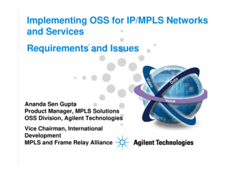
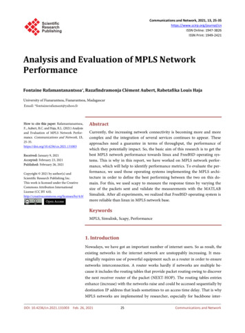
3INVOLVED TECHNOLOGIES AND PROTOCOLS3.1MPLS & MPLS VPNsMultiprotocol Label Switching is a technology specified in RFC 3031 (amongst others), whose mainpurpose is to forward packets based on so-called labels. Initially it was developed to avoid inefficienttraditional IP Routing (routing each packet by means of it's destination address and the usage of routingtables). MPLS is forwarding packets by using labels. Therefore a 32 bit long item will be added to thepacket header. These 32 bits mainly consist of the 20 bit long tag (the label, that is the basis for theforwarding decision) and three more fields (e.g a time-to-live field). The labels and their “meaning” arenegotiated by two neighboring routers by the usage of a protocol (mostly Label Distribution Protocol,LDP). Due to the adjustment of neighboring devices a central mechanism for the label management canbe avoided.“MPLS VPNs” is an independent, label-based technology with its own terminology (mainly described inRFC 4364). This technology is often compared to frame relay and ATM, because on a shared networkinfrastructure separated paths are established, transporting some customers' VPNs traffic. As for theterminology one must differentiate here between the provider network (P-Network) using MPLS and thecustomer network[s] (C-Network) accessing a corresponding service but not involved in any labeling.The transition points between customer and provider are called PE-Devices (Provider Edge) on theprovider’s side and a CE-Devices (Customer Edge) on the customer side. Usually a PE is serving multiplecustomers and for this reason not only maintains a “normal” routing table (here also called globalrouting table) but also maintains VPN specific routing tables, so called Virtual Routing and ForwardingInstances (VRFs) for each VPN. The PEs connecting the customers are sharing information about whichnet (prefix) is served by which customer, using Multiprotocol BGP (MP-BGP), an extended variant of theBorder Gateway Protocol (see above). The respective transmitted information is expressing sth like:“Thru me (PE) with some given label it is possible to reach this or that prefix (net) of this or thatcustomer”.Figure 1: Routing exchange with MP-BGPERNW Enno Rey Netzwerke GmbHBreslauerstr. 28D-69124 HeidelbergTel. 06221 – 48 03 90Fax 06221 – 41 90 08Ust-ID DE813376919Page 5
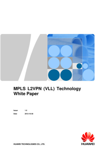
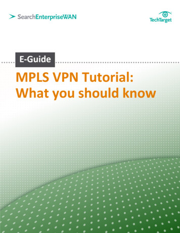
The VPN functionality can thus be summarized as follows:Every prefix of a customer VPN is getting a label assigned by a PE router. An information triplecontaining Route Distinguisher, net prefix and label, is then propagated by the PE to peering PEs, by MPBGP.Assuming that no filtering of routing information (using so-called route targets) is taking place, every PEknows which prefix/subnet is reachable by a certain customer through individual PE devices and whichlabels have to be used.Now, once a PE receives a packet of a customer device, this packet is labeled with at least two labelsand forwarded. One label identifies to the path to another PE and the other one is specifying to whichcustomer network the packet belongs to. So, in short, the whole VPN functionality is implemented by theuse of labels.3.1.1Trust ModelThe whole "core" (that is devices participating in label distribution and MP-BGP) is assumed to betrusted. MPLS does not dispose of any security properties on its own.3.1.2Security Controls Inherent to TechnologyMPLS doesn’t provide: Protection againstmis-configurations in the core Protection againstattacks from within the core Confidentiality, authentication, integrity, anti-replay- Use IPsec if required Customer network securityAPRICO2006MPLS Security 2005 Cisco Systems, Inc. All rights reserved Version 1.1 Jan-200666Figure 2: What MPLS doesn't provide, [12]3.2Carrier EthernetCarriers are increasingly offering services that provide end-to-end Ethernet connectivity across worldwide (mostly MPLS based) backbones. These services are often called something like “Carrier EthernetServices” or “International Ethernet VPN”. However enterprises know Ethernet predominantly as a LANtechnology where all user data is multiplexed over the network with limited separation or isolation.Furthermore, the consequences of the subsequent possible merger of Layer2 and Layer3 networks mightERNW Enno Rey Netzwerke GmbHBreslauerstr. 28D-69124 HeidelbergTel. 06221 – 48 03 90Fax 06221 – 41 90 08Ust-ID DE813376919Page 6
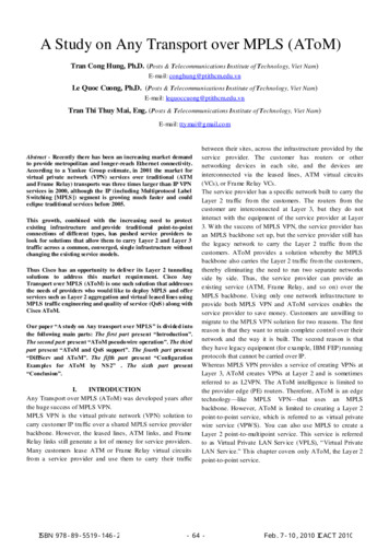
impose a whole new class of security risks that seem not too well understood, neither in carrier spacenor in enterprise environments.It should be noted that several scenarios must be distinguished when talking about “Ethernet in CarrierSpace”.First Ethernet may only be used as a medium (as opposed to a service) to access the carrier cloud(comparable to E1/T1, E3/T3, ATM, POS lines and the like) and “terminating” this line there’s a carriermanaged L3 device providing an Ethernet interface that supplies the site’s uplink connection (either tothe Internet, either to a VPN cloud). Cases of such mere Ethernet access1 are not considered in thisdocument, given there’s a carrier supplied CPE that constitutes a L3 boundary between the local networkand the carrier’s RED (untrusted) network.If the carrier product is intended to offer end-to-end Ethernet connectivity (as a service) and marketedwithin the “VPN product” space, the security aspects depend highly on the type of CE connecting a siteand on the type of device that’s sitting next to that CE (i.e. between the CE and the site’s local network).In case the CE is a Layer3 device (a router) – which usually does not happen with “Metro Ethernet” –there’s practically no difference to “MPLS Layer3 VPNs” as discussed above. In case the CE is a Layer2device (a switch) – which should apply to most “Carrier Ethernet Products” in the sense of this document– the device “behind it” (looking from the cloud) plays an essential role for the scenario’s security. It thisdevice is a router, this breaks the end-to-end Ethernet domain and induces a Layer3 boundary. Theresulting scenario can thus be regarded as the “own CE in Layer3 MPLS VPN” case which is discussedabove.If this next-to-CE-device is a Layer2 device (switch) and subsequently “real end-to-end Ethernet”2between the connected sites may be implemented, the security must be handled carefully. Unforeseenprotocol behaviour may arise and the overall security may heavily depend on the concrete configurationof the (carrier managed) CE. This scenario is the main focus of the discussion that follows.3.2.1Metro Ethernet“Metro Ethernet” is more of a collective term for several technologies providing Ethernet based accesslinks in metropolitan areas than a well-defined technology in itself (e.g. there is no “Metro EthernetRFC”). These technologies include MPLS based ones (described below) but historically the most widelyimplemented variant has been Ethernet over SONET/SDH3. Depending on the specific carrier product,“Metro Ethernet” can provide Point-to-Point connections or even Point-to-Multipoint or Any-to-Anyconnections. The main “standard body” for Metro Ethernet is the “Metro Ethernet Forum” [MEF,metroethernetforum.org], a global industry alliance comprising more than 120 organizations includingtelecommunications service providers, cable operators, MSOs, network equipment, test vendors, labsand software manufacturers, semiconductors vendors and testing organizations. The MEF’s main purposeis to develop “technical specifications and implementation agreements to promote interoperability anddeployment of Carrier Ethernet worldwide.” (quoted from MEF website).1This should apply to most carrier products of the FTTx or xDSL type offering cheap physical Ethernet lines as uplink connection,physically provided by means of some “plastic CPE”.2Please note discussion on “full vs. partial transparency” below.3Other technologies used for “Metro Ethernet” are Resilient Packet Rings (RPR, IEEE 802.17) or just “Ethernet Transport” fromthe access layer to the backbone.ERNW Enno Rey Netzwerke GmbHBreslauerstr. 28D-69124 HeidelbergTel. 06221 – 48 03 90Fax 06221 – 41 90 08Ust-ID DE813376919Page 7
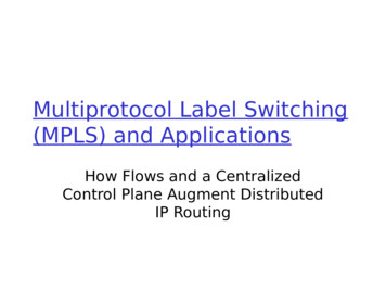
Figure 3: Ethernet Service – Basic Model, from [1]From an enterprise's security perspective “Metro Ethernet” links might always be treated as untrustednetworks given the variety of potential technologies involved and the pure Layer2 environment that canbe found in many cases. Additionally the following factors should be considered: The access link to the Carrier’s network might be a Layer 2 device (a switch) that connects severalcustomers (e.g. in business parks). Depending on this device’s configuration there might even exist a“shared L2 infrastructure” between some (or all) of the Carrier’s customers at this site, withsubsequent security problems. Usually a “Metro Ethernet” connection provides a fully transparent Ethernet link [see picture below]between the connected sites (in contrast to several MPLS based “Ethernet Services” where this linkmight not behave fully transparently). The MEF has published several “certifiable” specifications defining the details of different Ethernetservices. These specifications (in fact a Carrier’s compliance with them) may be used to identify thedetails of an offered service.ERNW Enno Rey Netzwerke GmbHBreslauerstr. 28D-69124 HeidelbergTel. 06221 – 48 03 90Fax 06221 – 41 90 08Ust-ID DE813376919Page 8
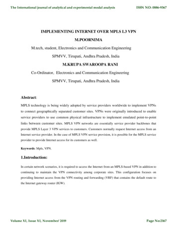
Figure 4: Example Service using E-LAN Service Type, from [1]3.2.2EoMPLS/ATOMEthernet-over-MPLS (EoMPLS) is a technology where the MPLS backbone is used not to transport IPpackets from one site to another (providing “Layer 3 service”) but to transport whole Ethernet frames(“Layer 2 VPN”). The signalling and labeled transport are comparable to Layer3 MPLS VPNs. Only pointto-point connectivity is provided; therefore EoMPLS does not scale very well.Both terms “EoMPLS” and “ATOM” are mostly used in the Cisco world.It is described (but not “specified”) in the (historic) RFC 4906 Transport of Layer 2 Frames Over MPLS4.The following diagram gives an idea of the functionality:4The most important “Standards Track” RFC for EoMPLS is RFC 4447- Pseudowire Setup and Maintenance Using the LabelDistribution Protocol (LDP) which also includes some security discussion.ERNW Enno Rey Netzwerke GmbHBreslauerstr. 28D-69124 HeidelbergTel. 06221 – 48 03 90Fax 06221 – 41 90 08Ust-ID DE813376919Page 9
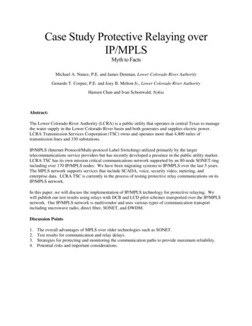
Figure 5: EoMPLS Example Network3.2.3VPLSVirtual Private LAN Service (VPLS) is an MPLS-based service and extends the pseudowire concept ofEoMPLS further effectively providing point-to-multipoint/any-to-any connectivity. Information which PEsare participating in one ‘LAN‘ is exchanged by some signalling protocol (BGP, LDP, others) and the VPLScloud is often regarded as a ‘big switch‘ [albeit a ‘big trunk‘ (in Cisco terms) would be more correct asthe cloud does not interact with most L2 protocols (which a switch generally does)]. The CE devices areusually switches. It can be expected that most “Carrier Ethernet” services will be VPLS-based in the nearfuture.A more detailed description can be found in [5]. Furthermore there are two RFCs (4761 and 4762)specifying two different flavors of VPLS (differing mainly as for the signalling protocol).It should benoted that RFC 4762 explicitly mentions “a case, [where] STP Bridge PDUs (BPDUs) are simply tunneledthrough the provider cloud”, thus expecting the PEs to behave “transparently” for (at least) sometype(s) of BPDUs. The following diagram gives an idea of the working mode of VPLS:ERNW Enno Rey Netzwerke GmbHBreslauerstr. 28D-69124 HeidelbergTel. 06221 – 48 03 90Fax 06221 – 41 90 08Ust-ID DE813376919Page 10
Figure 6: VPLS Working Mode Schema3.2.4L2TPv3The Layer 2 Tunneling Protocol, Version 3 (L2TPv3) can be used as a control protocol and for dataencapsulation to set up Pseudowires (PWs) for transporting layer 2 Packet Data Units across an IPnetwork. It is specified in (Standards Track) RFC 4719 Transport of Ethernet Frames over Layer 2Tunneling Protocol Version 3 (L2TPv3) and RFC 3931.3.2.5Full vs. Partial TransparencyDepending on the (carrier’s) service/product, potentially the devices used and the configuration of PEand CE the connection may or may not provide full transparency.“Full transparency” means, that all BPDUs (including e.g. STP, DTP, VTP, GVRP, LACP, 802.1x packetsand the like) and all Layer2 Headers (incl. VLAN tags, CoS) are transparently transported from one siteto another/others across the cloud5.In contrast “partial transparency” means that some of the BPDUs or header information isfiltered/discarded when entering the cloud.From a customer perspective “full transparency” offers some advantages (for instance the ability toimplement corporate wide VLANs or QoS policies without interaction with the carrier) but might alsoinduce new security risks resulting mainly from a lack of understanding of the impact on network(management) communication (see below for a more detailed discussion). To implement businessreasonable controls it might hence be helpful to figure out in advance if full or partial transparency is/willbe in place.3.2.6Trust ModelMostly the same as with MPLS ("Layer 3") VPNs disucssed above.5A User Network Interface Type 1.1 UNI-N as of the Metro Ethernet Specification could for example provide such a fully (or atleast mostly) “transparent” service.ERNW Enno Rey Netzwerke GmbHBreslauerstr. 28D-69124 HeidelbergTel. 06221 – 48 03 90Fax 06221 – 41 90 08Ust-ID DE813376919Page 11
3.2.7Security Controls Inherent to TechnologiesThese are the same that traditional Ethernet disposes of, that means practically none.3.3LDPThe Label Distribution Protocol, initially specified in the RFC 3036, is a signaling protocol for distributinglabels for a label switched path in an MPLS network. In 2007 RFC 5036 was released and replaces theold specification. LDP serves a set of procedures and messages by which Label Switched Routers (LSRs)establish Label Switched Paths through a network by mapping network routing information to data-linklayer switched paths. The procedures consist of four kind of functions: discovery functions, sessionmanagement, advertisement and notification.3.3.1Trust ModelLDP uses TCP to establish sessions between two LSRs. UDP is used for basic operations like discoverymechanisms which are periodically sent over the network to a well-known discovery port for all routersof a specific subnet. As these are sent to the “all routers on this subnet” group multicast address, withregard to the discovery process all routers on the local link are regarded trustworthy.3.3.2Security Controls Inherent to TechnologyTo protect the authenticity and integrity of LDP messages, LDP supports the TCP MD5 signature optionsdescribed in RFC 2385. It has to be activated at the LSRs and may protect the messages by validatingthe segment by calculating and comparing the MD5 digest. To use the MD5 option a preconfiguredpassword on each LSR is necessary.3.4BGPThe Border Gateway Protocol (BGP, most important RFC is number 1771 on BGP v4, dating from March1995) takes care of interconnecting the Internet's participating networks and provides dynamicpathfinding mechanisms by means of exchanging topology information. Devices implementing BGP toroute packets on the basis of this routing information and are called BGP routers. BGP speaking routerswith a direct relationship are considered as BGP neighbors or peers.3.4.1Trust ModelAs BGP uses a TCP based communication channel (which inherently does not work via multicastmessages, in contrast to many other routing protocols) the BGP peer usually have to be kind-ofpreconfigured by human operators. This might provide additional trust and security in the first place, stillit makes quite some parts of the BGP based Internet infrastructure susceptible to human error (AS 7007incident in the late 90s or YouTube/Pakistan incident in 2008) or to attacks by operator personnel (seefor example Kapela's/Pilosov's presentation at DefCon 2008).3.4.2Security Controls Inherent to ProtocolIn order to protect the TCP based communication BGP relies on the TCP MD5 Signature Option which hasbeen defined in RFC 2385. This option makes use of the Message Digest 5 (MD5) algorithm. The MD5Signature Option extends TCP in a way which allows to carry digest messages within TCP segments. Tocalculate the digest messages, additional information is used which in this case can be regarded as akind of passphrase.ERNW Enno Rey Netzwerke GmbHBreslauerstr. 28D-69124 HeidelbergTel. 06221 – 48 03 90Fax 06221 – 41 90 08Ust-ID DE813376919Page 12
3.5Additional Notes on the Security Features of Protocols Involved in DatacenterInterconnect ScenariosThe most common protocols for SAN traffic or replication are NFS, FCoE and iSCSI. While a detaileddiscussion of their respective functionality and specifications is not relevant for our discussion, it shouldnonetheless be noted that, again, most of them do not dispose of inherent security properties on theirown. A notable exception is NFSv4 which has some mature security mechanisms but the authors are notaware of many organizations using those.ERNW Enno Rey Netzwerke GmbHBreslauerstr. 28D-69124 HeidelbergTel. 06221 – 48 03 90Fax 06221 – 41 90 08Ust-ID DE813376919Page 13
4PRACTICAL ATTACKS4.1Tools4.1.1Loki6Initially the tool LOKI was meant to combine some stand-alone command line tools, like the bgp cli, theospf cli or the ldp cli and to give them a user friendly, graphical interface. In the meantime LOKI is morethan just the combination of the single tools; it enables its modules to base upon each other (likecombining ARP-spoofing from the ARP module with some man-in-the-middle actions, rewriting MPLSlabels for example) and even interoperate with each other.GUI:LOKI is based upon the GTK library. The base program creates the main window with the generalcommand-buttons and a few sub-windows, like the log-, the preference- or the about-window and astatus bar. In the center of the main window, it creates a notebook, with one tab for each module. Thetabs are filled with GTK-widgets from the module code. These widgets are fully under control of themodule code, so the main program doesn’t need to worry about.Traffic capturing:For capturing the network data, libpcap is used. The main program enumerates all network interfacesand gives the user a graphical interface to select the interface to use. Instead of capturing data live datafrom an interface, also a capture file can be opened. Once the interface, or input file, is selected, a newthread is created in the main program, which permanently captures the input data and demultiplexes itto the single modules.Traffic injection:Traffic injection is done via the dnet library. The LOKI main program creates a dnet instance for theselected interface and passes it directly to the modules.Firewalling:Firewalling is also done via the dnet library. The main program creates a global dnet firewall object andpasses it to the modules.4.2Attacking LDPLoki contains a universal LDP module, written in python. It implements the most common used LDPpacket and data types and can be used to participate in the LDP discovery process, as well as establishtargeted LDP sessions for advanced signaling. If such a targeted session is established, the tool starts abackground thread which sends keep-alive packages to hold the connection open and the signaled datavalid. To create such signaling data e.g. EoMPLS virtual circuits signaling, the module provides build-indata types which can be merged to the appropriated signaling packet.6See http://www.insinuator.net/2010/08/try-loki/ERNW Enno Rey Netzwerke GmbHBreslauerstr. 28D-69124 HeidelbergTel. 06221 – 48 03 90Fax 06221 – 41 90 08Ust-ID DE813376919Page 14
4.2.1An Example for signaling EoMPLS virtual circuitsThe peer is a Cisco 3750ME with a configured, but not activated virtual circuit:Figure 7: Cisco 3750 OutputLoki is the used to establish an LDP session and to send the necessary signaling information:Figure 8: Establishment of LDP Session with LokiFirst Loki needs to take part in the LDP discovery process; this is done by activating the Hello-Thread viaclicking on the “Hello” button. Next the remote host tries to connect the attacks host via TCP, so Lokineeds to listen for that incoming connection; this is done by activating the Listen-Thread via clicking onthe “Listen” button. Once the Connection is established, the remote Host will show up in the Host-List.The next step is to configure the LDP update message, which defines the signaling message to publish tothe remote host. In this case we generate a LDP Label-Mapping-Message. In the end we send theERNW Enno Rey Netzwerke GmbHBreslauerstr. 28D-69124 HeidelbergTel. 06221 – 48 03 90Fax 06221 – 41 90 08Ust-ID DE813376919Page 15
prepared update message by selecting the designated host from the host list and clicking on the“Update” button.After send the LDP Label-Mapping-message the configured virtual circuit is activated on the remote side:Figure 9: Cisco 3750 Console Output after using LokiSo we activated the virtual circuit and mapped it to a label defined in the update message. A tool likemplstun could be used to set up a valid endpoint on the attacker’s side.4.3Attacking BGPLoki contains a universal BGP module, written in python. It implements the most common used BGPpacket and data types and can be used to establish a connection to a BGP speaking peer. Once aconnection is established, the tool starts a background thread which sends keep-alive packages to holdthe connection established and the published routes valid. To publish BGP routing information themodule provides built-in data types which can be merged to the appropriated update statement. Oncean update statement is set up it can be send once or multiple times to the connected peer. It is possibleto use kernel based MD5 authentication, as described in RFC2385. Another module makes it possible tobrute force the used MD5 authentication key.4.3.1An Example for Injecting IPv4 Routing InformationThe peer is a Cisco 3750ME with a (pre-attack) routing table looking like this:Figure 10: Cisco 3750 Routing TableERNW Enno Rey Netzwerke GmbHBreslauerstr. 28D-69124 HeidelbergTel. 06221 – 48 03 90Fax 06221 – 41 90 08Ust-ID DE813376919Page 16
Loki is then used to inject IPv4 routing information:Figure 11: Injecting IPv4 Routing Information with LokiThe first step is to configuring the target IP address, the autonomous system number 2 and a hold timerof 8 seconds. Afterwards the session can be established by clicking on the “Connect” button. If Loki isable to establish the connection, a background keep alive thread is started, which sends an BGP keepalive packet every hold time / 4 seconds. The next step is to configure the BGP update message, whichdefines, the routing information to publish to the connected host. In the example case we build up aRFC1771 IPv4 routing BGP update packet which says we are announcing the network 192.168.233.0/24and traffic for this network should be forwarded to the IP address 10.0.0.2 which is our attack host. Inthe end we send the prepared update packet out by selecting the designated host from the connectionlist and clicking the “Update” button.ERNW Enno Rey Netzwerke GmbHBreslauerstr. 28D-69124 HeidelbergTel. 06221 – 48 03 90Fax 06221 – 41 90 08Ust-ID DE813376919Page 17
After publishing the routing information, the router’s routing table looks like this:Figure 12: Cisco 3750 Routing Table after using LokiSo we injected a route to the network 192.168.233.0/24 which, in this case, directs all matching trafficto our (attack) host.4.3.2Injection of MP-BGP RouteThe second example shows how to inject MPLS-VPN routing information (as described in RFC4364) into aMPLS Provider Edge router.The peer again is a Cisco 3750ME with a MPLS-VPN virtual routing and forwarding table associated withthe customer ‘RED’:Figure 13: Cisco 3750 MP-BGP Routing InformationERNW Enno Rey Netzwerke GmbHBreslauerstr. 28D-69124 HeidelbergTel. 06221 – 48 03 90Fax 06221 – 41 90 08Ust-ID DE813376919Page 18
Loki is then used to inject the MPLS-VPN routing informat
Figure 2: What MPLS doesn't provide, [12] 3.2 Carrier Ethernet Carriers are increasingly offering services that provide end-to-end Ethernet connectivity across world-wide (mostly MPLS based) backbones. These services are often called something like "Carrier Ethernet Services" or "International Ethernet VPN".