Transcription
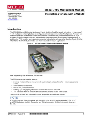
Model 7700 Multiplexer ModuleInstructions for use with DAQ6510Keithley Instruments28775 Aurora RoadCleveland, Ohio 441391-800-935-5595tek.com/keithleyIntroductionThe 7700 20-Channel Differential Multiplexer Plug-In Module offers 20 channels of 2-pole or 10 channels of4-pole multiplexer switching that can be configured as two independent banks of multiplexers. There are twoadditional protected channels for current measurements. Automatic cold junction compensation (CJC) isprovided so that no other accessories are required to make thermocouple temperature measurements. Inaddition, the 7700 contains latching electromechanical relays that enable signal bandwidths of up to 50 MHz.The 7700 is ideal for RTD, thermistor, and thermocouple temperature applications.Figure 1: 7700 20-Channel Differential Multiplexer ModuleItem shipped may vary from model pictured here.The 7700 includes the following features: 2-wire or 4-wire resistance measurements (automatically pairs switches for 4-wire measurements —n 10)Screw terminal connectionsBuilt-in cold junction referenceLatching type relays (relays hold their position after power is removed)Two protected channels for current measurements (external shunts not required)The 7700 can be used with the DAQ6510 Data Acquisition and Multimeter System.If you are using this switching module with the 2700, 2701, or 2750, please see Model 7700, 7702,and 7703 Multiplexer Modules Connection and Wiring Information, Keithley Instruments documentPA-695.077144300 / April 2018*077144300 *1
Model 7700 Multiplexer Module Instructions for use with DAQ6510ConnectionsConnection and wiring procedures in this document are intended for use by qualifiedpersonnel only. Do not perform these procedures unless qualified to do so. Failure torecognize and observe normal safety precautions could result in personal injury or death.Do not exceed the maximum specifications for the 7700. Refer to the specifications providedin the data sheet. Failure to recognize and observe normal safety precautions could result inpersonal injury or death.The following information describes how to make connections to the switching module and define the channeldesignations. A log is provided that you can use to record your connections. See Connection log (on page 5).This section describes how to make connections to the terminal screws in the module. You can make: Connections to DMM functions, which are provided through the module backplane connectorCurrent connections, provided through two protected channels (channels 21 and 22)INPUT connectionsSENSE (4-wire resistance) connectionsAMP and LO common connections to the instrumentWiring procedureUse the following procedure to wire the 7700 module. Make all connections using the correct wire size (up to20 AWG).All wiring must be rated for the maximum voltage in the system. For example, if 1000 V isapplied to the front terminals of the instrument, the switching module wiring must be ratedfor 1000 V. Failure to recognize and observe normal safety precautions could result inpersonal injury or death.2077144300 / April 2018
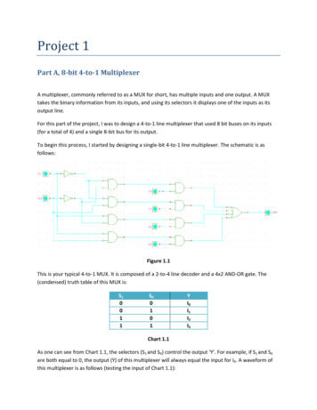
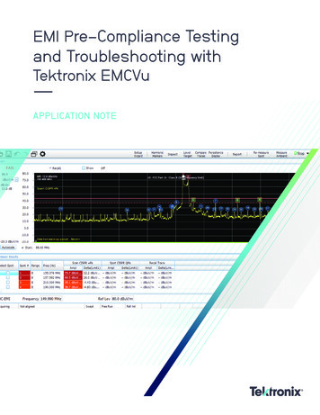
Model 7700 Multiplexer Module Instructions for use with DAQ6510Equipment needed: Small flat-blade screwdriverCable tiesTo make connections to the 7700 module:1. Make sure all power is discharged from the 7700 module.2. Use a screwdriver to turn the access screw to unlock and open the cover.Figure 2: Screw terminal access3. Use a small flat-blade screwdriver to loosen the terminal screws and install the wires as needed.Figure 3: 7700 screw terminal channel designations077144300 / April 20183
Model 7700 Multiplexer Module Instructions for use with DAQ65104. Route wire along the wire path and secure with cable tie as shown. The next figure also shows connectionsto channels 1 and 2.Figure 4: Wire dressing5. Record the connections in the Connection log (on page 5).6. Close the cover.7. Use a screwdriver to press in the access screw and turn to lock the cover.4077144300 / April 2018
Model 7700 Multiplexer Module Instructions for use with DAQ6510Connection logYou can use the next table to record your connection information.Connection log for the 7700ChannelAMPS 7144300 / April 20185
Model 7700 Multiplexer Module Instructions for use with 4300 / April 2018
Model 7700 Multiplexer Module Instructions for use with DAQ6510Remove a switching moduleBefore you remove a switching module, or begin any testing, make sure that all of the relays areopen. Since some relays may be latched closed, you must open all of the relays before removing theswitching module to make connections. Additionally, if you drop your switching module, it is possiblefor some relays to latch closed.To open all channels select Menu Control Open. If there are no channels closed, the Open button is notselectable.If any channel is closed, then the Open button is active and selecting it will open all channels.To prevent electric shock that could result in injury or death, never handle a switchingmodule that has power applied to it. Before installing or removing a switching module, makesure the DAQ6510 is turned off and disconnected from line power. If the switching module isconnected to a DUT, make sure power is removed from all external circuitry.If a card slot is unused, you must install slot covers to prevent personal contact with highvoltage circuits. Failure to install slot covers could result in personal exposure to hazardousvoltages, which could cause personal injury or death if contacted.Required equipment: Medium flat blade screwdriverMedium Phillips screwdriverTo remove switching module from the DAQ6510:1. Turn off the DAQ6510.2. Disconnect the power cord from the power source.3. Disconnect the power cord and any other cables that are connected to the rear panel.4. Position the DAQ6510 so you are facing the rear panel.5. Use the screwdriver to loosen the mounting screws that secure the switching module to the mainframe.6. Carefully remove the switching module.7. Install a slot plate or switching module in the empty slot.8. Reconnect the power cord and any other cables.InstallationBefore operating an instrument with an accessory switching module, verify that the switchingmodule is properly installed and the mounting screws are tightly fastened. If the mountingscrews are not properly connected, an electrical shock hazard may be present.077144300 / April 20187
Model 7700 Multiplexer Module Instructions for use with DAQ6510To use the switching operations, a switching module must be installed in the DAQ6510.If you are installing two switching modules, it is easier to install one switching module into Slot 2 first, theninstall the second switching module into Slot 1.If you have a Keithley Instruments Model 2700, 2701, or 2750 instrument, you can use your existingswitching module in the DAQ6510. Follow the instructions in your original equipment documentationto remove the module from the instrument, then use the following instructions to install it in theDAQ6510. You do not need to remove wiring to the module.For inexperienced users, it is recommended that you do not connect a device under test (DUT) andexternal circuitry to the switching module. This allows you to exercise close and open operationswithout the dangers associated with live test circuits. You can also set up pseudocards to experimentwith switching. Refer to Pseudocards in the Model DAQ6510 Reference Manual for information onsetting up pseudocards.To prevent electric shock that could result in injury or death, never handle a switchingmodule that has power applied to it. Before installing or removing a switching module, makesure the DAQ6510 is turned off and disconnected from line power. If the switching module isconnected to a DUT, make sure power is removed from all external circuitry.If a card slot is unused, you must install slot covers to prevent personal contact with highvoltage circuits. Failure to install slot covers could result in personal exposure to hazardousvoltages, which could cause personal injury or death if contacted.Required equipment: Medium flat blade screwdriverMedium Phillips screwdriverTo install switching module into the DAQ6510:1. Turn off the DAQ6510.2. Disconnect the power cord from the power source.3. Disconnect the power cord and any other cables that are connected to the rear panel.4. Position the DAQ6510 so you are facing the rear panel.5. Use the screwdriver to remove the slot cover screws and the cover plate. Retain the plate and screws forfuture use.6. With the top cover of the switching module facing up, slide the switching module into the slot.7. Press the switching module in firmly to make sure the switching module connector is connected to theDAQ6510 connector.8. Use the screwdriver to tighten the two mounting screws to secure the switching module to the mainframe.Do not overtighten.9. Reconnect the power cord and any other cables.8077144300 / April 2018
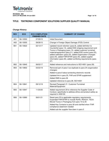
Model 7700 Multiplexer Module Instructions for use with DAQ6510OperationBefore installing or removing a 7700 module, make sure the instrument power is turned offand disconnected from line power. Failure to comply may result in incorrect operation andloss of data in the memory of the module.To prevent overheating or damage to the 7700 switching module relays, never exceed thefollowing maximum signal levels between any two inputs or chassis: Channels 1 to 20: 300 VDC or 300 VRMS (425 Vpeak) for AC waveforms, 1 A switched, 60 W,125 VA. Channels 21, 22: 60 VDC or 30 VRMS, 3 A switched, 60 W, 125 VA.Refer to the instrument documentation for operating instructions.Schematic diagramThe simplified schematic diagram of the 7700 is shown in the next figure.Channels 1 through 20 are used for all measurements except current. Channels 21 and 22 are used for currentonly.There are two backplane relays (channels 24 and 25) that connect the input channels to the backplane of theinstrument. With a 2-wire function (except current) selected, channel 25 closes. With a 4-wire function selected,both channels 24 and 25 close.There is a 2-pole/4-pole relay (channel 23) between channels 1 to 10 and channels 11 to 20. When a 2-wirefunction (such as DCV) is selected, channel 23 opens (2-pole position) to allow any of the 20 channels to beconnected to the input backplane.When a 4-wire function is selected, channel 23 closes (4-pole position) to isolate channels 1 through 10 fromchannels 11 through 20. When one of channels 1 to 10 is closed, its paired channel (11 through 20) also closesto connect the sense channel to the sense backplane.For the two current channels (21 and 22), signal HI and LO are routed directly to the backplane when thechannel is closed.The Input and Sense screw terminals are connected to the inputs of channels 24 and 25 (backplane isolationrelays). The AMPS screw terminal is connected directly to the DAQ6510.Channels 23, 24, and 25 in this schematic refer to designations used for control and not actualavailable channels. For more information, refer to the instrument reference manual. Also, AMPS andLO, in the next figure at the bottom, can be connected to another instrument, but you cannot controlthem through the front Panel, this includes using commands.077144300 / April 20189
Model 7700 Multiplexer Module Instructions for use with DAQ6510Figure 5: 7700 simplified schematic10077144300 / April 2018
Model 7700 Multiplexer Module Instructions for use with DAQ6510CalibrationThe following procedure calibrates the temperature sensors on the modules.Do not attempt to perform this procedure unless qualified to do so. Failure to recognize andobserve normal safety precautions could result in personal injury or death.Recommended test equipmentTo calibrate the module, you need the following equipment. Digital thermometer: 18 C to 28 C 0.1 CKeithley 7797 Calibration/Extender BoardExtender board connectionsThe extender board is installed in the DAQ6510. The module is connected to the extender board externally toprevent heating of the module during calibration.To make extender board connections:1. Remove power from the DAQ6510.2. Install the extender board into Slot 1 of the instrument.3. Plug the module into the P1000 connector on the rear of the 7797 Calibration/Extender Board.CalibrationBefore calibrating the temperature on the module, make sure that power has been removed from themodule for at least two hours to allow module circuitry to cool down. After turning on the powerduring the calibration procedure, complete the procedure as quickly as possible to minimize moduleheating that could affect calibration accuracy. Initially allow the DAQ6510 to warm up for at least onehour with the 7797 calibration card installed. If you are calibrating multiple modules sequentially, thenpower off the DAQ6510, quickly unplug the previously calibrated module, and plug in the next one.You must use remote commands to run calibration. Refer to the DAQ6510 reference manual (documentnumber DAQ6510-901-01) for information on setting up remote communications.To set up calibration:1. Turn on the DAQ6510 power.2. To make sure that the instrument is using the SCPI command set, send:*LANG SCPI3. Turn power off, and turn power back on.4. On the front panel, verify that TERMINALS is set to REAR.077144300 / April 201811
Model 7700 Multiplexer Module Instructions for use with DAQ6510To calibrate temperature:1. Accurately measure and record the cold temperature of the module surface at the center of the module withthe digital thermometer.2. Unlock calibration by sending::CALibration:PROTected:CODE "KI006510"3. Calibrate temperature on the module with the following command, where temp is the cold calibrationtemperature measured in step 1::CALibration:PROTected:CARD1:STEP0 temp 4. Send the following commands to save and lock out bration:PROTected:CARD1:LOCKErrors that can occur during calibrationIf calibration errors occur, they are reported in the event log. You can review the event log from the front panelof the instrument, by using the SCPI :SYSTem:EVENtlog:NEXT? command, or by using the TSPeventlog.next() command.The error that can occur on this module is "5527, Temperature Cold Cal error." If this error occurs, contactKeithley Instruments. Refer to Factory service (on page 24).Performance verificationThe performance of the module is tested by verifying the accuracy of measurements made through the module.If verification limits are met through the front-panel terminals of the DAQ6510, they should also be met throughthe module.Do not attempt to perform this procedure unless qualified to do so. Failure to recognize andobserve normal safety precautions could result in personal injury or death.Measurement accuracy through the module should only be verified after instrument accuracy hasbeen verified through the front-panel terminals of the DAQ6510. Refer to the DAQ6510 Calibrationand Adjustment manual (documentation number DAQ6510-905-01) for verification information.This verification procedure requires that the DAQ6510 be within its calibration interval.Module verification test procedures include: 12DC voltsAC voltsResistanceTemperatureFrequencyRatio and average077144300 / April 2018
Model 7700 Multiplexer Module Instructions for use with DAQ6510Make sure that you perform the verification tests using the following conditions: Under the proper environmental conditions.After the specified warm-up period.With connections made to the correct input terminals.Using the correct line voltage.With the TERMINALS switch in the REAR position.With the proper calibration equipment and the reading limits provided with the verification procedures. SeeCalculating resistance reading limits (on page 13) for more information.Environmental conditionsConduct your performance verification procedures in a test environment that has: An ambient temperature of 18 C to 28 C.A relative humidity of less than 80% unless otherwise noted.Warm-up periodAllow the DAQ6510 to warm up for at least one hour before verifying the module.If the instrument has been subjected to temperature extremes (those outside the ranges stated above), allowadditional time for the internal temperature of the instrument to stabilize. Typically, allow one extra hour tostabilize an instrument that is 10 C outside the specified temperature range.Allow the test equipment to warm up for the minimum time specified by the manufacturer.Example reading limit calculationThe following is an example of how reading limits have been calculated. Assume you are testing the 10 VDCrange using a 10 V input value. Using the DAQ6510 one-year accuracy specification for 10 VDC of (25 ppmof reading 5 ppm of range), the calculated limits are:Reading limits 10 V [(10 V 25 ppm) (10 V 5 ppm)]Reading limits 10 V (0.00025 0.00005)Reading limits 10 V 0.00030 VReading limits 9.99970 V to 10.00030 VCalculating resistance reading limitsResistance reading limits must be recalculated based on the actual calibration resistance values supplied bythe equipment manufacturer. Calculations are performed in the same manner as shown in the previousexample, except that you should use the actual calibration resistance values instead of the nominal valueswhen performing your calculations.For example, assume that you are testing the 10 kΩ range using an actual 10.03 kΩ calibration resistancevalue. Using DAQ6510 one-year 10 kΩ range accuracy of (75 ppm of reading 6 ppm of range), thecalculated reading limits are:Reading limits 10.03 kΩ [(10.03 kΩ 75 ppm) (10 kΩ 6 ppm)]Reading limits 10.02929 kΩ to 10.03081 kΩ077144300 / April 201813
Model 7700 Multiplexer Module Instructions for use with DAQ6510Recommended test equipmentThe table below summarizes recommended verification equipment. You can use alternate equipment if thatequipment has specifications if that equipment has specifications that meet or exceed those listed below. Beaware that calibrator uncertainty adds to the uncertainty of each measurement.Fluke 5700A Calibrator:DC voltageAC voltage (1 kHz, 50 kHz)Resistance100 mV: 14 ppm100 mV: 200 ppm100 Ω: 17 ppm1.0 V: 7 ppm1.0 V: 82 ppm1 kΩ: 12 ppm10 V: 5 ppm10 V: 82 ppm10 kΩ: 11 ppm100 V: 7 ppm100 V: 90 ppm100 kΩ: 13 ppm1000 V: 9 ppm700 V: 85 ppm1 MΩ: 18 ppm10 MΩ: 37 ppm100 MΩ: 120 ppmFluke 5725A AmplifierAC Voltage, 50 kHz: 700 V, 375 ppmThe Fluke 5725A amplifier is necessary only if you need to verify the 750 VAC range at 50 kHz.Verification at 220 V and 50 kHz using the 5700A calibrator is adequate for most applications.Keithley 3930A or 3940 Frequency Synthesizer1 VRMS, 10 VRMS, 1 kHz, 5 ppm, steady state and burst modulationGeneral Radio 1433-T Precision Decade Resistance Box10 Ω to 400 Ω, 0.02%Miscellaneous equipmentDouble banana plug to double banana plug shielded cables (two)BNC to double banana plug shielded cable14077144300 / April 2018
Model 7700 Multiplexer Module Instructions for use with DAQ6510Performance verification proceduresThe following procedures describe how to check one channel (CH1) or one channel pair (CH1 andCH11) of the module. To check other channels or channel pairs, modify the procedures byconnecting the verification equipment to the appropriate channel or channel pair.When performing the verification procedures: Make sure that the equipment is properly warmed up and connected to the correct input terminals.Make sure that the TERMINALS switch is set to REAR.Do not use autoranging for any verification tests. Autorange hysteresis may cause the DAQ6510 to be onan incorrect range. For each test signal, you must manually set the correct range for the DAQ6510.Make sure the calibrator output is enabled before you verify each measurement.Always let the source signal settle before taking a reading.The verification limits stated in this section have been calculated using only the DAQ6510 one-year accuracyspecifications, and they do not include test equipment uncertainty. If a particular measurement falls slightlyoutside the allowable range, recalculate new limits based on both DAQ6510 specifications and pertinentcalibration equipment specifications.Do not attempt to perform this procedure unless qualified to do so. Failure to recognize andobserve normal safety precautions could result in personal injury or death.The maximum common-mode voltage (the voltage between any module terminal and chassisground) is 300 VDC or 300 VRMS. Exceeding this value may cause a breakdown in insulation,creating a shock hazard.Verifying DC voltageTo check DC voltage accuracy, apply accurate voltages from the DC voltage calibrator to the input terminals ofthe module and verify that the displayed readings fall within specified limits.Do not exceed 300 VDC between plug-in module INPUT H and L terminals or between anyadjacent channels. Failure to observe this precaution can cause instrument damage.077144300 / April 201815
Model 7700 Multiplexer Module Instructions for use with DAQ6510To verify DC voltage accuracy:1. Connect the CH1 H and L INPUT terminals to the DC voltage calibrator as shown in the next figure.Use shielded, low-thermal connections when testing the 100 mV and 1 V ranges to avoid errorscaused by noise or thermal effects. Connect the shield to the output LO terminal of the calibrator.Figure 6: 7700 .Install the module in Slot 1 of the DAQ6510.Turn on the power.Allow the instrument to warm up for one hour.Make sure that the front-panel TERMINALS switch is set to REAR.On the front panel of the instrument, select the FUNCTION key and then select DC Voltage.On the Home screen, swipe to the CHANNEL swipe screen.Close channel 101.Set the range to 100 mV.Set the calibrator output to 0.00000 mV DC.Allow the reading to settle.Swipe to the Settings screen.Enable Rel.For the calibrator, source positive, negative, and full-scale voltages, see the ranges listed in the tablebelow. For each voltage setting, make sure that the reading is within stated limits.15. Return to the CHANNEL swipe screen, and open Channel 1.16RangeApplied DC voltageReading limits (1 year, 18 C to 28 C)100 mV100.0000 mV99.9935 to 100.0065 mV1V1.000000 V0.999969 to 1.000031 V10 V10.00000 V9.99970 to 10.00030 V100 V100.0000 V99.9955 to 100.0045 V1000 V300.000 V299.983 V to 300.017 V077144300 / April 2018
Model 7700 Multiplexer Module Instructions for use with DAQ6510Verifying AC voltageTo check AC voltage accuracy, apply accurate AC voltages at specific frequencies from the AC voltagecalibrator to the module inputs. Verify that the displayed readings fall within specified ranges.Do not exceed 300 VRMS between the INPUT H and L terminals or between adjacent channels,or 8 107 V Hz input. Failure to observe this precaution may result in instrument damage.To verify AC voltage accuracy:1. Connect the CH1 H and L INPUT terminals of the module to the AC voltage calibrator, as shown in the nextfigure.Figure 7: Connections for AC volts verification2.3.4.5.6.7.8.9.10.11.12.Install the module in Slot 1 of the DAQ6510.Turn on the power.Allow the instrument to warm up for one hour.Make sure that the front-panel TERMINALS switch is set to REAR.On the front panel of the instrument, select the FUNCTION key and then select AC Voltage.On the Home screen, swipe to the CHANNEL swipe screen.Close channel 101.Set the range to 100 mV.Swipe to the Settings screen.Disable Rel.Source 1 kHz and 50 kHz AC voltages for each of the ranges summarized in the table below. Make surethat the respective DAQ6510 readings are within stated limits.13. Return to the CHANNEL swipe screen, and open Channel 1.077144300 / April 201817
Model 7700 Multiplexer Module Instructions for use with DAQ6510ACV rangeApplied AC voltage1 kHz reading limits(1 year, 18 C to 28 C)50 kHz reading limits(1 year, 18 C to 28 C)100 mV100.0000 mV99.910 to 100.090 mV99.830 to 100.170 mV1V1.000000 V0.99910 to 1.00090 V0.99830 to 1.00170 V10 V10.00000 V9.9910 to 10.0090 V9.98300 to 10.0170 V100 V100.0000 V99.910 to 100.090 V99.830 to 100.170 V750 V300.000 V*299.60 to 300.40 V299.27 to 300.73 V* If the 5725A amplifier is not available, change the 300 V @ 50 kHz step to 220 V @ 50 kHz. Reading limitsfor 220 V @ 50 kHz 219.36 V to 220.64 V.Verifying resistanceCheck resistance by connecting accurate resistance values to the module and verifying that its resistancereadings are within the specified limits.Do not apply more than 300 VDC between the module INPUT or SENSE H and L terminal orbetween any adjacent channels. Failure to observe this precaution can cause instrumentdamage.To verify resistance accuracy:1. Using shielded Teflon or equivalent cables in a 4-wire configuration, connect the 7700 CH1 H and L INPUTterminals and CH11 H and L SENSE terminals to the calibrator as shown in the next figure.Figure 8: Connections for resistance verification2.3.4.5.6.7.8.9.10.11.18Install the module in Slot 1 of the DAQ6510.Turn on the power.Allow the instrument to warm up for one hour.Make sure that the front-panel TERMINALS switch is set to REAR.Set the calibrator for 4-wire resistance with external sense on.On the front panel of the instrument, select the FUNCTION key and then select 4W Resistance.On the Home screen, swipe to the CHANNEL swipe screen.Set the range to 100 Ω range.Swipe to the Settings screen.Enable the Filter.077144300 / April 2018
Model 7700 Multiplexer Module Instructions for use with DAQ651012. For the 100 Ω range, select the MENU key, select Channel Settings, and set Offset Compensation to On.13. Recalculate reading limits based on actual calibrator resistance values.14. Source the nominal full-scale resistance values for the 1 Ω to 100 MΩ ranges listed in the table below.Verify that the readings are within calculated limits.Ω RangeNominalresistanceNominal reading limits(1 year, 18 C to 28 C)Recalculated limits**1 Ω*1Ω0.999715 mΩ to 1.000285 Ωto Ω10 Ω10 Ω9.99895 mΩ to 10.00105 Ωto Ω100 Ω100 Ω99.9895 Ω to 100.0105 Ωto Ω1 kΩ1 kΩ0.999929 Ω to 1.000081 kΩto kΩ10 kΩ10 kΩ9.99929 Ω to 10.00081 kΩto kΩ100 kΩ100 kΩ99.9905 Ω to 100.0095 kΩto kΩ1 MΩ1 MΩ0.999894 Ω to 1.000106 MΩto MΩ10 MΩ10 MΩ9.99590 Ω to 10.00410 MΩto MΩ100 MΩ100 MΩ99.7970 Ω to 100.2030 MΩto MΩ* Enable offset compensation for the 1 Ω range.** Calculate limits based on actual calibration resistance values and DAQ6510 one-yearresistance accuracy specifications. See Calculating resistance reading limits (on page 13) formore information.1.2.3.4.Connect the CH1 and CH11 terminals of the module to the calibrator as shown in the next figure.Disable external sense on the calibrator.Set the range of the DAQ6510 to 100 MΩ range.Source a nominal 100 MΩ resistance value. Verify that the reading is within calculated limits for the 100 MΩrange.5. Return to the CHANNEL swipe screen, and open Channel 1.Figure 9: Connections for resistance verification (100 MΩ range)077144300 / April 201819
Model 7700 Multiplexer Module Instructions for use with DAQ6510Verifying temperatureThermocouple, thermistor, and RTD temperature readings are derived from DC volts and resistancemeasurements, respectively. For that reason, it is not necessary to independently verify the accuracy oftemperature measurements. If the DC volts and resistance functions meet or exceed specifications,temperature function accuracy is automatically verified.You can verify temperature accuracy using the following procedures (Thermocouple temperature (on page 20)and RTD temperature (on page 21)).Thermocouple temperatureThis setup and reading limits table below does not include errors from ice point, thermocouple wire, andconnections. HI and LO connections from the calibrator and 7700 must be electrically isolated from each other.To verify the thermocouple temperature:1. Connect the DC voltage calibrator output terminals and ice point reference to the CH1 H and L INPUTterminals of the module using low-thermal shielded connections, as shown in the next figure.Figure 10: Connections for thermocouple temperature verification2.3.4.5.6.7.8.9.20Install the module in Slot 1 of the DAQ6510.Turn on the power.Allow the instrument to warm up for one hour.Make sure that the front-panel TERMINALS switch is set to REAR.On the front panel of the instrument, select the FUNCTION key and then select Temperature.On the Home screen, swipe to the CHANNEL swipe screen.Close channel 101.Set the channel to temperature.077144300 / April 2018
Model 7700 Multiplexer Module Instructions for use with DAQ651010. Configure the channel for C units, type K temperature sensor, and internal reference junction as follows:a. Press the MENU key.b. Select Channel Settings.c. Set the Transducer to TC.d. Set the Thermocouple to K.e. Set the Unit to Celsius.f. Set the Reference Junction to Internal.11. Source each of the voltages in the table below and verify that the temperature readings are within limits.Make sure to select the appropriate thermocouple type for each group of readings.12. Return to the CHANNEL swipe screen, and open Channel 1.In the next table, note that two thermocouple types are provided with specifications for each. Pay attention tothe type of thermocouple you are verifying when referring to the table in order to apply your resultsappropriately. Also, note that you can verify both types of thermocouples using this procedure for each, one ata time.Thermocouple typeApplied DC voltage*Reading limits (1 year, 18 C to 28 C)J-7.659 mV-192.33 C to -187.67 C0 mV-1.0 C to 1.0 C42.280 mV749.0 C to 751.0 C-5.730 mV-192.33 C to -187.67 C0 mV-
Model 7700 Multiplexer ModuleInstructions for use with DAQ6510 077144300 / April 2018 3 . Equipment needed: Small flat-blade screwdriver Cable ties . To make connections to the 7700 module: 1. Make sure all power is discharged from the 7700 module. 2. Use a screwdriver to turn the access screw to unlock and open the cover.