Transcription
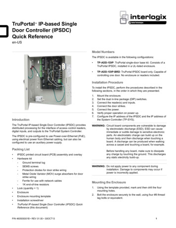
TruPortal IP-based SingleDoor Controller (IPSDC)Quick Referenceen-USModel NumbersThe IPSDC is available in the following configurations: TP-ADD-1DIP: TruPortal single-door base kit. Consists of aTruPortal IPSDC, installed in a UL-listed enclosure. TP-ADD-1DIP-BRD: TruPortal IPSDC board only. Capable ofcontrolling one door. No enclosure or readers included.Installation ProcedureTo install the IPSDC, perform the procedures described in thefollowing sections, in the order in which they are presented.IntroductionThe TruPortal IP-based Single Door Controller (IPSDC) providesdistributed processing for the interface of access control readers,digital inputs, and outputs to the TruPortall System Controller.The IPSDC is pre-configured to use Power-over-Ethernet (PoE),using electrical power from Ethernet cabling, but can also beconfigured to use an auxiliary power supply.1.2.3.4.5.6.7.WARNING: Circuit board components are vulnerable to damageby electrostatic discharge (ESD). ESD can causeimmediate or subtle damage to sensitive electronicparts. An electrostatic charge can build up on thehuman body and then discharge when touching aboard. A discharge can be produced when walkingacross a carpet and touching a board, for example.Packing List IPSDC printed circuit board (PCB) assembly and overlay Hardware kit- Ground terminal lugSEMS screwsProtection diodes for door strike wiringMetal Oxide Varistor (MOV) surge absorbers for doorstrike wiringFerrite for use with network cables1K end-of-line resistorsLock (quantity 1) Enclosure Enclosure mounting template Installation screwdriver TruPortal IP-based Single Door Controller (IPSDC) QuickReference (this document)P/N 460939301B REV 01.00 30OCT13Mount the enclosure.Set the dual in-line package (DIP) switches.Connect the reader(s) and inputs.Connect the door strikes.Connect the power.Verify proper operation on power up.Configure the IP address of the IPSDC and the IP address ofthe System Controller (TP-SYS).Before handling any board, make sure to dissipateany charge by touching the ground. This dischargesany static electricity build-up.WARNING: Do not apply power to any component duringinstallation. Damage to components may occur ifpower is incorrectly applied.Mounting the Enclosure1.Using the template provided, mark and then drill the fourmounting holes.2.Bolt the enclosure securely to the wall, using four #8 threadlag bolts or equivalent.1
Setting the DIP SwitchesSet DIP switches before installing and wiring readers. See Figure10 on page 7 for switch locations.SwitchPurposeSW1 – Select CustomWiegand Card Format[1]Set SW1-1 to OFF and set SW1-2 thruSW1-4 to ON.SW2Set all four DIP switches to OFFThe following table provides switch settings for input types:SW1-5 and SW1-6SW1-7SW1-8Supervised DI/REX 1,4-StateN/AONN/ASupervised DI/REX 1,2-State (default)N/AOFFN/AAfter changing DIP switch settings to modify input types,be sure to reboot the IPSDC.Switches SW4—SW7 are right-angle, momentary-contact pushbuttons described in the following table and shown in Figure 11 onpage 8.SwitchPurposeSW4 – Boot ModeManually enables the ICT. See the TruPortalSoftware User Guide for details.SW5 – Hardware ResetReboots the IPSDC. Use this switch only ifperforming a controlled manual shutdown, asinstructed by Technical Support.SW6 – Shutdown RequestSee Safe Shutdown Procedure on page 5.SW7 – Restore DefaultsPress SW7 for a minimum of five (5) seconds,then release to return the configuration to factorydefault settings:Primary Connection Type: EthernetIP Address: 192.168.6.6Subnet Mask: 255.255.255.0Gateway: 192.168.6.1Note: The reader interface has built-in pull-up resistors toaccommodate cable lengths over 500 feet (152.4 meters). Noexternal pull-up resistors are required for the reader interface.Table 1: Maximum Peripheral LoadsReader/Strike1. Use the System Administration Card Formats pagein the TruPortal User Interface to configure Wiegandcard formats.Note:The inputs can be configured as supervised or nonsupervised. Inputs configured as supervised digital inputsrequire End-of-Line (EOL) resistors.The reader board address is internally set to Address 1.Connecting the Readers and InputsUse Figure 10 on page 7 to wire the readers and inputs. Refer tothe reader documentation for wiring instructions.PoEAuxiliary Power SupplyVoltage (DC)12241224Total watts available8101220Note:A TruPortal IPSDC Power Requirement WattageCalculator is included on the product disc in the\Documentation\en-US folder for use in determiningperipheral loads.Table 2: Device t (mA)WattsT-100 reader1255.66T-200 reader1255.66T-500 reader12951.14T-520 reader121051.26T-525 reader121401.68Securitron M62 Magnalock122402.88241403.36HES, Inc 5000-12/24D strike122302.76HES, Inc 5000-12/24D strike241152.76Rutherford 4114x05x32D strike121902.28Von Duprin 5100 3FP69512 VDC122904.68Von Duprin 5100 3FP69524 VDC241954.68RCR-REX12280.34RCR-REX24170.41strike [1]Securitron M62 Magnalockstrike [1]1. When using magnetic strikes with auto-voltage select, additional power allowances must be considered due to autovoltage circuitry operation.Note the following details: IPSDCs do not support the following TruPortal features:Buzzer actions initiated by action triggers, auxiliary inputs/outputs, and reader tamper inputs. The reader DI port (J2) has two digital inputs which are usedfor door status devices (door contacts and exit request input).2TruPortal IP-based Single Door Controller Quick Reference
Connecting the Door StrikesFigure 2: Door Strike Configuration Using External PowerOne door DO relay is dedicated to the J2 reader port. The doorDO is used for strike control, and may implement an external relayif necessary.Figure 1: Door Strike Configuration Using Internal Power (PoE or 24 VDC)CalloutDescription1Strike Relay Normally Closed (NC)2Strike Relay CommonCalloutDescription3Strike Relay Normally Open (NO)1Strike Relay NC4Protection diode required[1]2Strike Relay Common512 or 24 VDC Strike[2]3Strike Relay NO6Strike voltage selection. Jumper pins 1 and 2 for 24 VDC strikes;jumper pins 2 and 3 for 12 VDC strikes.4Protection diode required[1]512 or 24 VDC Strike[2]7See strike manufacturer’s installation guide for conductor size(AWG).6Strike voltage selection. Set jumper to Neutral (no connection)position.7See strike manufacturer’s installation guide for conductor size(AWG)8Strike power supply9Provide current restriction device, less than 2 amps through relay.1. Use 1N4002, 1N4003, or 1N4004 diodes.2. Refer to the TruPortal IPSDC Power Requirements WattageCalculator worksheet included on the product disc for striketype and size.The following table describes connector J2 in Figure 2.1. Use 1N4002, 1N4003, or 1N4004 diodes and Metal OxideVaristors (MOVs) for AC strikes.2. Refer to the TruPortal IPSDC Power Requirements WattageCalculator worksheet included on the product disc for striketype and size.TruPortal IP-based Single Door Controller Quick Reference3
Grounding Procedure and Regulatory InformationNote:All bullets must be followed for regulatory compliance. All cables connected to the IPSDC must be shielded withshield terminated as shown in Figure 3. Use #8-32 SEMSscrews provided. When wiring readers, ground the shields of the cable at theIPSDC enclosure grounding studs to avoid electrical noise. The IPSDC enclosure must be connected to the nearestearth ground. (See Figure 4.) A convenient earth ground, such as an electrical box or aground bus, must be provided to the IPSDC enclosure. The earth ground connection must be made to the terminallug provided. Mount the terminal lug to the PEM nut on thebottom of enclosure using the #8-32 SEMS screw provided,as shown in Figure 4. Use #14-18 AWG wire. Before connecting the network cable to connector J10, loopthe cable through ferrite provided as shown in Figure 5.Note:Figure 5: Installing FerriteFerrite must be installed inside of the enclosure.Figure 3: Using Shielded Cable and Drain WireConnecting the PowerThe IPSDC provides two methods of connecting power, both ofwhich are sold separately: Network connector J10 as PoE. (See Figure 6). Auxiliary power connector J8 with network hub POE device or24 VDC supply with battery backup (Figure 7).Figure 6: Connecting Through PoE HubFigure 4: Wiring Earth GroundUsing PoENot evaluated by UL.41.Install a PoE supply (IEEE802.3af 16 watt Class 0 Mode A orB PoE Power Sourcing Equipment (PSE)) in accordance withthe manufacturer's instructions.2.By Ethernet standards, the maximum cable length is limitedto 328 ft. (100 m) between the PoE source and the IPSDC.3.Attach supplied ferrite to the network cable by looping thenetwork cable through the ferrite as shown in Figure 5.4.Connect the network cable to connector J10 on the IPSDC.5.Connect the other end of the network cable to the PoE supplyper the manufacturer’s instructions.TruPortal IP-based Single Door Controller Quick Reference
Figure 7: Connecting Through Network Hub Using PoE or Auxiliary SupplyConfiguring the IPSDCAfter an IPSDC is installed, follow the instructions in the TruPortalSoftware User Guide to use the browser-based IntegratedConfiguration Tool (ICT) to: Configure the IPSDC to recognize the IP address of theSystem Controller (TP-SYS). Change the IP address of the IPSDC.Following is an overview of that procedure; see the TruPortalSoftware User Guide or online help for details.Using an Auxiliary Power SupplyThe IPSDC requires a 24 VDC nominal, 1 amp power supply withbattery backup. The IPSDC, readers, and other devices should bereferenced to the same ground.For UL-listed installations, the auxiliary power supply must be anapproved UL294 power-limited supply, such as the Altronix Corp.Model AL176ULX power supply. For UL of Canada (ULC)installations, the auxiliary power supply must be listed to S319 orS318.1.Mount the power supply near the IPSDC enclosure.2.Run the wire through the knockout hole to connector J8 (seeFigure 8). Pinouts include: Pin 1 24 VDC Pin 2 – Ground (24 VDC return)Note:If the polarity is reversed, the fuse blows to preventdamage. If the fuse blows, it automatically resets withinapproximately five (5) seconds.1.Configure a local client workstation for static IP address192.168.6.1 or a similar valid IP address (e.g., 192.168.6.xwhere x is any number between 1 and 254 except 6).2.Make sure that the PC is not blocked from connecting to IPaddress 192.168.6.6. (If the workstation normally connects tothe Internet via a proxy, the proxy settings in the browser mayneed to be adjusted.)3.Open an Internet browser and go to http://192.168.6.6, thedefault address of the IPSDC.4.Type the User ID and Password for the ICT.The default values are install and install.5.On the Controller Parameters Primary Network page,configure the correct IP address for this IPSDC. A static IPaddress is highly recommended. Make a note of the addressfor your records. Click Save and then Apply.6.On the Controller Parameters Panel Configuration page,type the IP address of the System Controller. Click Save andthen Apply.7.Click Restart Application to commit the changes.After a few minutes, the IPSDC will be accessible via the newIP address and can be detected by the System Controllerwhen the [Scan for Hardware Changes] button is clicked inthe TruPortal User Interface.8.Repeat the procedure for each IPSDC.Safe Shutdown ProcedureFigure 8: Auxiliary Power Supply WiringThe following procedure can be performed in maintenance modeor normal operation mode to turn off the IPSDC.WARNING: Do not reset or restart the IPSDC in the middle of afirmware update or the IPSDC will becomenonfunctional. Refer to the TruPortal Software UserGuide for more information about firmware updates.Note:5For UL-listed installations, Pin 3 is used for AC PowerFail notifications; Pin 5 is used for Low Batterynotifications.1.Press SW6 and hold the button for three seconds until LEDsD14 through D21 turn on and stay on. (See Figure 11 forlocations of reset switches and LEDs.)2.Wait for about five seconds.Remove power to the IPSDC or push SW5 to reset theIPSDC.CalloutDescriptionWire Color3.1 24 VDC from auxiliary power supplyRedNote:2Ground (0V) from auxiliary power supplyBlack3Factory-wired chassis ground. Do not remove.Green4 24 VDC auxiliary power supplyThe halt state lasts for approximately 40 to 45 seconds,after which the IPSDC will automatically restart.TruPortal IP-based Single Door Controller Quick Reference
Figure 9: IPSDC Board LayoutThe following table lists the items shown in Figure 9.6CalloutDescriptionCalloutDescription1IPSDC board with overlay11Network (Ethernet) port J102Reader In (Access) J112Console port J93Door Contact, Request to Exit (RTE) andStrike Relay J213Enclosure tamper W54Strike Voltage Select W214Boot Mode switch SW45Custom Wiegand Card Format DIP switchSW115Hardware Reset switch SW56Reader Out (Egress) J316Shutdown Request switch SW67DIP Switch 2 (set all to OFF) SW217Restore Defaults switch SW78Status LEDs typical18Aux Power Input 24 VDCNote: Jumpers between pins 3 and 4, and pins 4and 5 must remain in place.9UCSIMMPlus Module19Fire Alarm Control Panel (FACP) Input J6Note: The IPSDC does not support FACP sothis jumper must remain in place.10IPSDC board mounting holesTruPortal IP-based Single Door Controller Quick Reference
Figure 10: Wiegand WiringThe following table lists the items shown in Figure 10.CalloutDescriptionWire ColorCalloutDescription171K EOL resistors typical[3]Wire ColorConnector J1Connector J31Reader 1 (access)18Reader 2 (egress)2 12 VDCRed19 12 VDCRed3Ground (0V)Black20Ground (0V)Black4Reader Data 0Green21Reader Data 0Green5Reader Data 1White22Reader Data 1White6Door DO (green LED)Orange23Door DO; green LEDOrange7—9Not used24—26Not used10Drain wire (cable shield)[1]27Drain wire (cable shield). See footnote 1Connector J211Door DI (DC )12Door DI Return (DC-)13Exit DI (REX )14Exit DI Return (REX-)15Door Contact[2]16REX [2]TruPortal IP-based Single Door Controller Quick Reference1. Use 20 AWG shielded cable and terminate drain wire(cable shield) at enclosure (see Figure 3 on page 4).Use plenum-rated cable if cable will be run above afalse ceiling in the air circulation space.2. Door or Exit DIs Normally Open or Closed.3. Include resistors for Wiegand Four-State interface.For Wiegand Two-State interface, omit resistors.7
Figure 11: IPSDC LEDs and SwitchesCalloutDescriptionState1D85 Power OnON: power is present2D14 OfflineNormally OFF3D15 Address RXNormally OFF4D16 Badge ActivityNormally OFF; flashes when badge is read5D17 Database PendingFlashes while waiting to receive database from host6D18 File System ActiveNormally OFF7D19 WatchdogFlashes one beat per second if watchdog is healthy8D20 Flash UploadON when IPSDC is booting up9D21 Shutdown RequestNormally OFF/Flashes and then ON10D33 Strike ActivatedON during strike activation11D24 FACP (not supported by IPSDC)ON contact open12D25 Door ContactON contact closed; OFF contact open; Flashing fault13D26 Door REXON contact closed; OFF contact open; Flashing fault14DS and DS5 LinkON link activity; OFF no activity. Flashing network activity15DS4 and DS8 CollisionON Collision16DS3 and DS7 Full DuplexON Full duplex; OFF Half duplex17DS2 and DS6 100/10 MbpsON 100 Mbps; OFF 10 Mbps18SW4 Boot ModeManually enables the ICT.19SW5 Hardware ResetReboots the IPSDC.20SW6 Shutdown RequestInitiates Safe Shutdown of the IPSDC.21SW7 Restore DefaultsReturns configuration to factory defaults.LEDsSwitches8TruPortal IP-based Single Door Controller Quick Reference
Regulatory InformationSpecificationsDimensions (Height Width Depth)10.15 in. x 9.15 in. x 3.04 in.(258 mm x 232 mm x 77 mm)Operatingenvironment 35 to 122 F ( 2 to 50 C)ManufacturerInterlogixHeadquarters and Regulatory responsibility:Interlogix3211 Progress Dr.Lincolnton, NC 28092 USAEU authorized manufacturing representative:UTC Climate, Controls & Security B.V.,Kelvinstraat 7, 6003 DH Weert,The NetherlandsYear ofmanufactureThe first two digits of the product serial number (locatedon the product identification label) are the year ofmanufacture.North AmericanstandardsUL 294FCCcomplianceThis device complies with part 15 of the FCC Rules.Operation is subject to the following two conditions: (1)This device may not cause harmful interference, and (2)this device must accept any interference received,including interference that may cause undesiredoperation.EnvironmentalClassUL: Indoor drytemperature[1]Humidity range[2]5 to 95% non-condensingThermal air coolingAt least 6 in. (15.2 cm) of clearance is required on allfour sides of the enclosure.Power inputrequirementsIPSDC to readercablingIEEE802.3af 16 watt Class 0 Mode A and B PoE/PSE) on Standard Category 5 (CAT 5) Ethernet cableNote: By Ethernet standards, the maximum cablelength is limited to 328 ft. (100 m) between the PoEsource and the IPSDC.-orAuxiliary 24 VDC 1 A local supply (24 watts).Reader voltage: 12 VDCNote: If the cable distance is greater than 500 feet(152.4 m), but less than or equal to 2000 feet(609.6m) and/or the current per reader is greater than150 mA, use 20 AWG shielded cable.If the cable distance is less than 500 feet (152.4 m),use 22 AWG shielded cable.Recommended: Use 20 AWG shielded cable to wirereader, DOs, and DIs. Use plenum-rated cable forapplications where cable will run above a false (i.e.,suspended) ceiling in the air circulation space.Recommended: Alpha Xtra Guard1 foil shield cable,non-plenum-rated, or Belden-series security andalarm cable (commercial applications shielded),plenum-rated.ReadersMaximum number of readers supported: 2Reader technology supported: WiegandOutput devices maximum ratings: Door DO (ReaderLED) 20.mA @ 12 VDC maximum; Door strike(DO) relay 2 A @ 28 VDC or 30 VAC maximumStrikesMaximum current: 390 mA per strike output. SeeTable 2 on page 2 for recommended strike modelsand associated power requirements.NetworkrequirementsAlthough IPSDCs are equipped with a fallback mode,they should be placed on a network with an adequatereliability rate. (A network reliability rate of 99.98percent is typical for mission-critical operations.)If a typical Mean Time To Repair (MTTR) goal is onehour, then using the 99.98% reliability rate equates toa mean network reliability, or Mean Time BetweenFailure (MTBF), goal of approximately 5,000 hours (or1hr/.0002). In other words, the network that theIPSDC is being placed on (from the door controller tothe System Controller), should not fail more often thanonce every 5,000 hours (or approximately 208 days)on average.UL evaluation for UL-Listed Installations:1. 32 to 120 F (0 to 49 C)2. Up to 85% non-condensingCertificationEuropean UniondirectivesWe declare under our sole responsibility that this productis in conformity with Directive 1999/5/EC (R&TTE), 2004/108/EC (EMC), 2006/95/EC (LVD), and 93/68/EEC(Marking) based on test results using harmonizedstandards in accordance with the Directives mentioned.Contact Informationwww.interlogix.comCustomer support: www.interlogix.com/support 30OCT13 United Technologies CorporationInterlogix is part of UTC Climate Controls & Security, a unit ofUnited Technologies Corporation. All rights reserved.Document number: 460939301B - October 2013TruPortal IP-based Single Door Controller Quick Reference9
4 TruPortal IP-based Single Door Controller Quick Reference Grounding Procedure and Regulatory Information Note: All bullets must be followed for regulatory compliance. All cables connected to the IPSDC must be shielded with
