Transcription
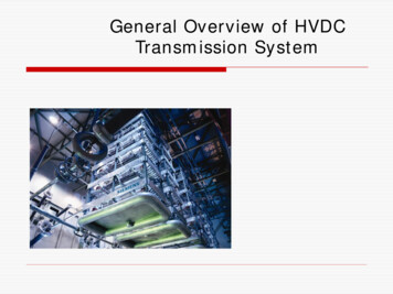
General Overview of HVDCTransmission System
WHAT IS HVDC ? High Voltage Direct Current Transmission Only Active Power Flow is associated with HVDC: P. High Voltage Alternative Current Transmission Both Active and Reactive Power (Var) Flows with AC: P and QHVDC1-Phase( )HVAC3-Phase
What is HVDC ?Basic Image : DC vs. AC Transmission DC1-Phase ( ge/PowerDistance Voltage/Power – Decrease (Loss) Angle – No stance Voltage/Power – Decrease (Loss) Angle – Change (Reactive Power)
WHAT IS HVDC ?Sending SideDirect CurrentId (Vs-Vr)/R ACRVs–Receiving SideVrRSending VoltageVsReceiving VoltageVr Basic Power Flow Equations Only Governed by Ohm’s LawVs (Vs Vr )Power RAC
WHAT IS HVAC ?Sending SideVsReceiving SideX(Reactance)VsLθVr Basic Power Flow Equations Power VrVs Vrsin θX Governed by Reactance- Var from Inductance & Capacitance
HVDC Advantages (1) Long-Haul Over Head Line ( 500 1000km)Bulk Power Transmission ( 1 2 GW) No limitation of stability (Free from stability & capacitance limitation) HVDC transmission line has less right of way requirement& less expensive in construction (HVDC 2-phase; HVAC 3phase) Lower transmission loss because of no reactive loss Lower insulation/clearance of conductor (DC Voltage isabout 71% of the AC Peak Voltage. AC is defined by RMS) Power transmission between asynchronous AC systems
HVDC Advantages (2) Fast Power Flow control Enhancement of AC system stability Supplying more active power where AC system is at thelimit of its Short Circuit Capability
HVDC Disadvantages HVDC is generally less reliable and has lower availabilitythan HVAC. Mainly due to the extra conversion equipment and maintenancedifficulty. Tapping for Multiple grids is difficult. HVDC circuit breakers are difficult Some mechanism must be included in the circuit breaker to forcecurrent to zero Pollution deterioration of Outdoor Insulator is faster Static Charge effect AC Filters are required to absorb harmonic component Clean room (Dust free) for Thyristor Valve is necessary
Comparison HVDC with HVAC#ItemHVDCHVAC1Long-Haul OHLBulk Transmission CapacityHigh( 1 2GW)Limited2Long-Haul Transmission StabilityNo LimitLimited3Right-of-Way for BulkTransmission OHLLowHigh4Long-Haul Transmission LossLowHigh5Insulation / ClearanceLowHigh6System ConnectionAsynchronousSynchronous7Power Flow ControlEasy and FastDifficult6Multiple terminal (Tapping)Difficult and CostlySimple and Easy7Short Circuit LimitationEffectiveNot Effective8Pollution Effect More Pronounced Higher insulator creepage isrequiredRelatively less
Why HVDC rather than HVAC ? Cheaper in Long-Haul Bulk Power transmission Asynchronous link Accurate Control of power flow – both magnitudeand direction Fault isolation Improved link stability
Comparison of Right of Way for 2 GW400 500 kV AC Lines 100 m400 500 kV DC Line 50 m1 2GW Bulk Power Transmission
Cost comparison of HVDC & HVACOHL TransmissionCostTotal AC CostBreak-Even DistanceTotal DC CostAC Line CostDC terminal CostDC Line CostAC terminal Cost600 800 kmDistance
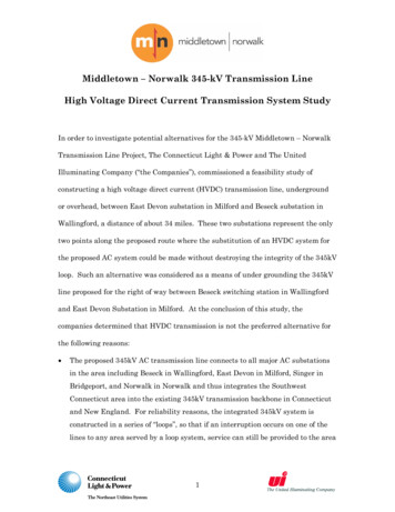
Types of HVDC Transmission system Monopole System: One pole, one set of conductor for transmission andcurrent return path is through earth. Mainly used for submarine cable transmission.AC1AC2SubmarineDC Cable(HVDC Line)Earth/Water(Return Path)
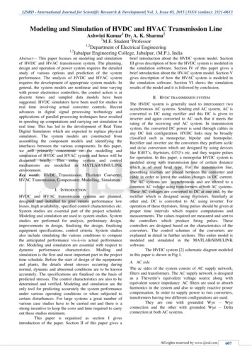
Types of HVDC Transmission system Bipolar System: Two poles, two set of conductors in transmission line, one positivewith respect to earth & other negative The mid point of Bi-poles in each terminal is earthed via anelectrode line and earth electrode. In normal condition power flows through lines & negligible currentthrough earth electrode. (in order of less than 10 Amps.)AC1HVDC LineOHL/Cable ( )Neutral LineReturn Path ( 0)HVDC LineOHL/Cable (–)AC2
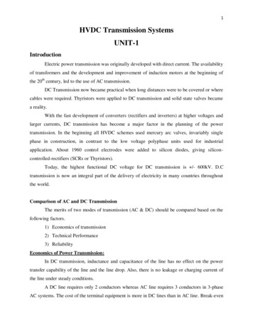
Types of HVDC Transmission system Back To Back: Usually bipolar without earth return.Converter & inverters are located at the same place.No HVDC Transmission line.Provides Asynchronous tie between two different AC networkPower transfer can be in either directionAC1AC2
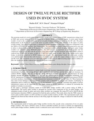
Types of HVDC Transmission system Multi Terminal System: Three or more terminals connected in parallel, some feed power andsome receive power from HVDC Bus. Provides Inter connection among three or more AC network.AC1AC2AC3
HOW HVDC WORKS
Basic Diagram of HVDC SystemTERMINAL ADCTERMINAL B(Converter)LINE(Converter)AC 1IdLdAC 2LdPd Vd IdVdFILTERFILTER
6-Pulse Convertor Bridge (Valve)Id135462DC OutputY YAC Input
12-Pulse Convertor Bridge (Valve)DC OutputY YY AC Input
HVDC Thyristor Valve (1)SingleValveDoubleValveQuadruple Valve(Multiple Valve Unit : MVU)
HVDC Thyristor Valve (2)ThyristorDriveUnitThyristorModuleMultiple Valve Unit
HVDC Converter Transformers & FiltersConverter TransformerAC Filters
HVDC Station (3000MW)
BIPOLE HVDCMODES OF OPERATION
BASIC HVDC Single Line DiagramSmoothing ReactorThyristorValvesDC Filter:DC OH LineSmoothing ReactorDC Filter:ConverterTransformerConverterTransformerDC Filter:AC BusAC FiltersThyristorValvesDC Filter:AC BusAC Filters
Modes of Operation (1)BipolarCurrentCurrent
Modes of Operation (2)Monopole Ground ReturnCurrentCurrent
Modes of Operation (3)Monopole Metallic ReturnCurrentCurrent
than HVAC. Mainly due to the extra conversion equipment and maintenance difficulty. Tapping for Multiple grids is difficult. HVDC circuit breakers are difficult Some mechanism must be included in the circuit breaker to force current to zero Pollution deterioration of Outdoor Insulator is faster Static Charge effect