Transcription
OPERATOR MANUALMini-Bank 1500
Table of ContentsTABLE OF CONTENTS1. INTRODUCTION1.1 Features1.1.1 About the Mini-Bank 1500 1.2 Specifications1.2.1 Mini-Bank 1500 Specifications1.2.1.1Dimensions1.2.1.2Component Locations1.2.1.3LCD & Customer Keypad1.2.1.4Cash Dispensing Unit1.2.1.5Receipt Printer1.2.1.6Main Control Board1.2.1.7Operating Environment1.3 Warranty/Service2. INSTALLATION2.1 Mini-Bank 1500 Installation2.1.1 Unpacking2.1.2 Physical Installation2.1.3 Hardware Setup3. PROGRAMMING3.1 Initial Setup3.1.1 Accessing the Operator Function Menu3.1.2 When An Error Occurs3.1.3 Mini-Bank Keypad3.1.4 NanoCash Keypad3.2 The Host Setup Menu3.2.1 Key Management3.2.2 Set Host Telephone Number3.2.3 Set Terminal ID / Routing ID Number3.2.4 Health Check Message3.2.5 Connect Timer3.2.6 Remote Monitor3.2.7 Trial Day Total3.3 The System Setup Menu3.3.1 Set Clock3.3.2 Speaker / LCD Control3.3.3 ISO 1,2,3 En/Disable3.3.4 Optional Languages3.3.5 Change Passwords3.3.6 Modem Setup3.3.7 Modem Test3.3.8 RMS Ring Count3.4 Customer Setup Menu3.4.1 Change Message3.4.2 BIN Lists3.4.3 Optional Function3.4.4 Receipt Setup3.4.5 Surcharge Mode3.4.6 AdvertisementsDoc. No. 101205Operator Manual
Table of ContentsOperator Manual3.5 Transaction Setup3.5.1 Dispense Limit3.5.2 Denomination3.5.3 Fast Cash3.5.4 Low Currency Check4. OPERATION4.1 Opening and Closing4.1.1 Mini-Bank4.1.1.1Opening the Security Door4.1.1.2Closing the Security Door4.1.1.3Opening the Front Panel4.1.1.4Closing the Front Panel4.1.1.5Operating and Changing the Combination Lock4.2 Cash Operations4.2.1 Mini-Bank4.2.1.1Adding Cash to the Cassette4.2.1.2Emptying the Reject Bin4.2.1.3Loading the Receipt Printer4.3 Settlement Menu4.4 Journal Menu4.5 Reports Menu5. DIAGNOSTICS5.1 Diagnostics Menu6. CUSTOMER TRANSACTIONS6.1 Opening Procedure6.2 Withdrawal Transaction6.3 Balance Inquiry Transaction6.4 Transfer Transaction6.5 Closing Procedure6.6 Error RecoveryAPPENDIXA. Error CodesB. Pin Pad layout for Master Key / Download Mode / Clear NVRAMC. TDES Master Key installationD. Advertisement GraphicsDoc. No. 101205
IntroductionOperator ManualMini-Bank 1500 1.1 FEATURES1.1.1 ABOUT THE Mini-Bank 1500 The Tranax Mini-Bank1500 represents the absolute best value in retail ATMs. TheMini-Bank 1500 inherits the unsurpassed reliability and quality of the MB-1000 and2000. An eye-catching design coupled with numerous enhancements to ensure ADA,TDES and VISA PIN security compliance, makes the Mini-Bank 1500 the clearchoice for any retail ATM deployment.The new Mini-Bank 1500 has standard features such as voice guidance, encryptedpin pad and 56K modem. It offers a range of options to custom configure an ATMsolution for any location. No other ATM manufacturer offers the same level ofintegrated design and built in flexibility. The Tranax Mini-Bank 1500 delivers highquality and high performance at a value price.H/W FEATURESUL 291 Business Hour Service Vault featuring reinforced steel bottom.Dial combination lockElectronic combination lock (optional)320 x 240 resolution of back-lit LCD / color display (option)Dial-up telephone line instead of expensive leased line1100 new note capacity2000, 4000 new note capability (optional)DIP type magnetic card readerThermal receipt printer for high speed printingModular design for easy maintenanceFUNCTIONAL FEATURESCashworks Check Cashing (optional)Electronic journal stores up to 2000 transactionsSupports English, Spanish, French, Korean, Japanese (optional)Availability for 7 on screen advertisement graphicsDetailed average history report featureError code description for easy serviceDoc. No. 1012051.1
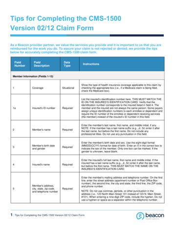
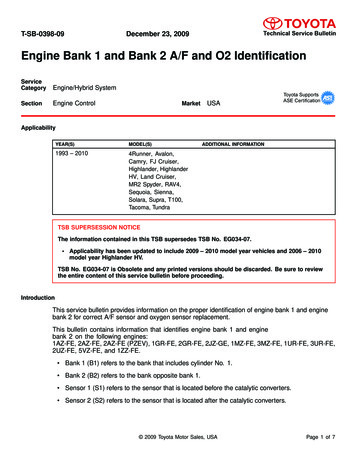
IntroductionOperator Manual1.2 SPECIFICATIONSMini-Bank 1500 SPECIFICATIONS1.2.1 DimensionsFig. 1 Mini-Bank DimensionsWEIGHT: 269 lbs.Doc. No. 1012051.2
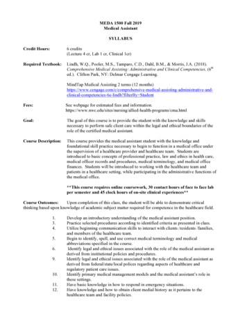
IntroductionOperator Manual1.2.2 LCD & Customer KeypadFig. 3 LCD & Customer KeypadLCDScreen Size: 6”Mono/Color (optional)Resolution: 320 x 240Display Characters: 40 x 15 (Standard Characters)8 Menu KeysKEYPADLab Certified VISA compliant EPP (Encrypting Pin Pad)10 Alphanumeric, 3,4, CANCEL, CLEAR, ENTER, BLANK KeypadsEach Keypad has integral raised Braille symbolsVoice Guidance PortVoice assisted operation available through the headphone jack on the front bezelDoc. No. 1012051.3
IntroductionOperator Manual1.2.3 Cash Dispensing UnitCash Dispensing Unit(Standard drawer type)CASH DISPENSING UNITDispensing Speed: 4 notes/secondCapacity of 1100 new notes per tray (standard dispenser)Capacity of optional dispensers* depending on model.Reject Bin with capacity of 200 notesLow Level Cassette Detection (not available in 1000 note cassette configuration)Double note detect module*Optional dispensers include:1000 note removable cassette2000 note removable cassette4000 note removable dual cassetteDoc. No. 1012051.4
IntroductionOperator Manual1.2.4 Receipt PrinterReceipt PrinterRECEIPT PRINTERThermal line printer36 characters/lineSemi-automatic roll paper settingMotorized front push rollersPAPER SPECIFICATIONSOne sided thermal paperFactory paper is thermal side out (but either way will work)7.0 inch outside diameter roll3.125” inch wideCore inside diameter 11/16 inch21# weight (paper thickness)Doc. No. 1012051.5
IntroductionOperator Manual1.2.5 Main Control BoardModem: 56,000 bps dial-up modem (standard)Electronic Journal: /- 2,000 transactionsBattery back-up for set-up parameters (NVRAM)Real time clock1MB RAM1.2.6 Operating EnvironmentPOWER REQUIREMENTS110/220 VAC 10%, 50/60 Hz, 250 WattsPOWER CONNECTIONSFor warranty purposes, the Mini-Bank 1500 series ATM must be connected to adedicated power circuit. This circuit must consist of line, neutral, and ground leadsconnected directly to the power circuit breaker panel. This circuit should not beshared with any other equipment. Use of a surge protector or uninterruptible powersupply is recommended.PHONE LINE REQUIREMENTSThe Mini-Bank series ATM should be connected to a dedicated phone line. This linemust be a direct dial “tone” or “pulse” line that is equipped with a standardtelephone wall jack (RJ-11). This line cannot be shared with any other equipment atthe location. Use of shielded (CAT5) phone cable is recommended for bestperformance and to reduce the chance of interference.TEMPERATUREIn storageWhile operating: 32 F - 123 F (0 C 49 C): 40 F - 95 F (5 C 35 C)HUMIDITYIn storageWhile operatingDoc. No. 101205: 10% RH 90%, non-condensed: 15% RH 85%, non-condensed1.6
IntroductionOperator Manual1.3 WARRANTY/SERVICEMANUFACTURERS WARRANTYTranax Technologies, Inc. provides a limited one-year parts warranty and a limited30 day labor warranty for the MiniBank series ATM. Tranax guarantees yourMiniBank ATM to be free from defects in materials and workmanship.The one-year parts warranty and 30-day labor warranty periods will begin 15 daysfrom the shipping date.WHAT IS COVERED:· Cash Dispensing Unit (CDU) and Cash Cassette· Receipt printer (SHU)· LCD module· Magnetic Card Reader (MCR)· EPP Keypad· Power Supply· Mainboard (CE)· Lock and locking mechanism **LIMITED 90 DAY WARRANTY**Dial and Electronic locks will be covered by a limited 90-day warranty providedthe warranty registration card is completed and returned to Tranax within 10days of installation. Should the lock fail under normal use, Tranax will replacethe lock only. Services required to open the vault and or replace the lock are atthe expense of the ATM owner.WHAT IS NOT COVERED:· Power cable and modem cable· Key lock and key· Plastic Bezels· Software upgrade· Receipt printer jam· Note jam· Forgotten password or combination of lock· Any damages from misuse, improper installation, and vandalism· Any damages from “brown out” or low power, lightning, or any other acts of GodYour distributor/dealer may offer an enhanced or extended warranty in addition tothe original manufacturers one-year warranty. Once the manufacturers warrantyhas expired, all claims for warranty service must be resolved directly between thedistributor/dealer and the ATM owner. Tranax will only honor the extended warrantyof a MiniBank ATM that is registered in the Tranax Extended Part Replacement (EPR)warranty program.OBTAINING SERVICE: If you have any problems or questions about your TranaxATM, your dealer or distributor is your primary contact for assistance/service. Yourmanufacturers warranty is provided through your dealer or distributor.Doc. No. 1012051.7
Section 2: InstallationOperator ManualSECTION 2: INSTALLATION2.1 MINI-BANK 1500 INSTALLATION2.1.1 UNPACKINGStep 1Once the ATM is unpackaged, do not discard the packaging materials until you haveverified any shipping damage claim. Contact your distributor immediately if you seeany shipping damage.Step 2Verify the contents carefully with the packing list to be sure all items listed areincluded. Notify your distributor of any shortages.2.1.2 PHYSICAL INSTALLATIONTo install the Mini-Bank 1500 ATM, perform the following steps:Step 1Place the system on a flat surface. The system has a tendency to tip over if thesurface is over 10 degrees. Be careful when opening the top or bottom of themachine as it will be off balance.Step 2Locate the Anchor Template in the bottom of the vault. Use the template to drill theappropriate sized holes for the anchors you will be using. (Anchors are notincluded). Tranax does not recommend a particular size or type of anchor as eachinstallation is different however maximum anchor diameter is ½Step 3Install the anchors into the ground according to the anchor bolts locate sheet (4places). See manufacturers instructions for anchor installation.Step 4Place the Mini-Bank ATM on top of the anchors.Step 5Open the Security cover with the key provided. See page 4.1 for Opening andClosing instructions.Doc. No. 1012052.1
Section 2: InstallationOperator ManualStep 6Using the supplied combination (factory preset at 50-25-50), open the security Door.This combination should be changed as soon as possible. Refer to page 4.5 (dial) or4.7 (electronic) for instructions on opening or changing the lock.Step 7After the anchor nuts are in place, according to the anchor holes on the bottom ofthe Mini-Bank, secure the anchor bolts snugly. Do not over tighten anchors as itmay distort the vault and cause problems with the door linkage.END2.1.3 HARDWARE SETUPStep 1Verify the power voltage (115/220V) to be used and set theappropriate voltage on the power supply. Default will be115V. The default setting should be 115VStep 2Verify that the telephone line to be used for the ATM is in proper working order.Tranax recommends the use of shielded (CAT5) phone line in locations with closeproximity to other appliances.Step 3Open the security door and remove any shipping materials and note any warning orinstallation instructions. See page 4.1 for assistance.Step 4Remove the cash cassette from the box (removable cassette dispensers only). Fillthe cassette or cash drawer with the appropriate amount of notes, and carefullyplace it in the Cash Dispensing Unit. Place the appropriate denomination label on thefront of the cassette. See page 4.9 for instruction.Step 5Before closing the vault, thoroughly test the combination lock by locking andunlocking the lock several times. It is much easier to diagnose potential lockproblems before shutting the door.Doc. No. 1012052.2
Section 2: InstallationOperator ManualStep 6Open the top of the ATM. Place the receipt paper in the Receipt Printer. The paperprints only on one side (shiny side) always check the roll when you install paper.Place the roll so that the coated side (shiny side) will be facing up. See page 4.12 forpaper loading instruction.Step 7Connect the Power cable and the telephone cable to the appropriate outlets on thewall. Verify that the AC power outlet is grounded. If you are installing theilluminated topper, make sure to completely install the power cord into the A/C Outplug on the power supply. The socket takes an extra push to fully seat the plug.Step 8Turn the power on and verify that all systems are operational. If any part on thesystem or its programming is not operational, an error code will be displayed. If anerror code is displayed, corrective action will be listed below it. If the error cannotbe corrected, please contact your distributor. If no error code is displayed, enter theOperator Function Menu and view the Error Summary (see programming section).ENDDoc. No. 1012052.3
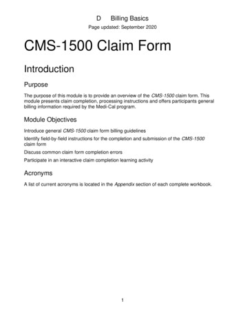
Section 3: ProgrammingOperator ManualSECTION 3: PROGRAMMING3.1 INITIAL SETUP3.1.1 ACCESSING THE OPERATOR FUNCTIONStep 1To access the Operator Function menu, hold the Cancel , Clear and Enter keys simultaneously for 2 seconds, release them and press 1, then press 2, thenpress 3. The timing of this procedure can be difficult at first.Note: The Operator Function menu can only be accessed when the machine is eitherin service (“swipe your card” screen) or out of service. If the machine is attemptingto connect the host or initializing, you will not be able to use the key commands toaccess the Operator Function Menu.If you have trouble accessing the Operator Menu, power off the ATM and then eitheropen the vault door or remove the paper from the printer and power back on. Thiswill force the ATM to the Operator Menu.Step 2Once you successfully completed the keycombination, you will be prompted to enter apassword. There are 3 options for passwords. Operator Password (allows access to basicmenu structure)Service Password (allows access to basicand diagnostic menus)Master Password (allows access to allmenus including setup parameters)Passwords are very important to maintainingsecurity for your ATM. Yourdealer/distributor will provide you withdefault password information.NOTE: Tranax Technologies, Inc. highlyrecommends changing your passwords fromdefault as soon as possible. Passwords MUSTbe 6 digits in length, use of anything otherthan a 6 digit password may cause thepasswords to revert back to factory default.Doc. No. 1012053.1
Section
Introduction Operator Manual Doc. No. 101205 1.7 1.3 WARRANTY/SERVICE MANUFACTURERS WARRANTY Tranax Technologies, Inc. provides a limited one-year parts warranty and a limited 30 day labor warranty for the MiniBank series ATM. Tranax guarantees your MiniBank ATM to be free from defects in materials and workmanship.