Transcription
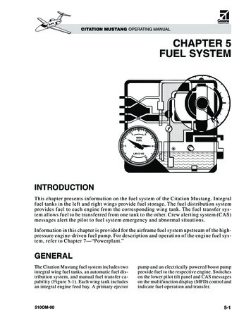
30001-30002 Instructions Layout 1 6/16/15 2:56 PM Page 1FiTechTMFuel InjectionNote: These kits are notlegal for use on pollution controlled vehiclesInstruction Manualfor the following Go EFI Systems30001, 30002, 30004, 30012, 30061, 30062 & 30064This Quick Start Manual is designed to get you up andrunning with the Go EFI System Base Kit and either the40003 Fuel Command Center or the 40005 Inline Fuel Delivery Kit. The FiTech Go EFI System is the industry'smost advanced throttle body EFI system and also the easiest to install. It includes a very advanced Handheld Controller but is also capable of being far more tunable thanany competitive product that utilizes a Handheld Controller. Please read the full instruction manual before beginning your installation.These instructions cover the Basic Kit installation andsetup as well as instructions for both of the optional FuelDelivery Kits. For technical assistance with your Go EFISystem, call 951-340-2624.Warning: Caution must be oberved when installing any product involving fuel system parts or gas tank modificaitons.Work in a well ventilated area with an approved fire extinguisher readily available. Eye goggles and other safety apparelshould be worn to protect against debris and sprayed gaso-line. We recommend having this installation performed by anexperienced qualified automotive technician. The finished installation must be thoroughly checked for any fuel systemleaks. All safety precautions must be observed when workingwith fuel. Note: Do not use solid core ignition wires.30001/30002/30004/30012/30061/30062/30064 Kit Contents(1) 4-Injector Throttle Body - Tumbled Polished (30001) or,(1) 4-Injector Throttle Body - Matte Black Finish (30002) or,(1) 4-Injector Throttle Body - Matte Black Finish (30004) or,(1) 8-Injector Throttle Body - Matte Black Finish (30012) or,(2) 4-injector Throttle Bodies - Tumbled Polished (30061) or,(2) 4-injector Throttle Bodies - Matte Black Finish (30062) or,(2) 4-injector Throttle Bodies - Matte Black Finish (30064)(1) Harness "A" (Plug-in pigtail user harness)(1) ECU (Mounted on Throttle Body)(1) Set of four or eight injectors pre-installed(1) Idle Air Control (Installed on Throttle Body)(1) Throttle Position Sensor (Mounted on Throttle Body)(1) Coolant Sensor(1) Handheld Controller w/billet case(1) Wide Band O2 Sensor(1) O2 Sensor Bung Kit(1) Fuel Pressure Regulator (Installed in Throttle Body)(1) Gasket Kit(2) -06 AN Inlet/Outlet Fittings (Installed on Throttle Body(3) Inlet/Outlet Port Plugs (Two installed on Throttle Body)(1) Data Com Cable(1) 8 gigabyte SD Card (Installed in Controller)(1) 3/8-NPT Reducer(1) 10mm Port Plug(1) Instruction BookletTable of Contents for Instruction Manual:Kit Contents. 1About your FiTech Go EFI System.2Fuel Delivery Requirements.2/ 3Oxygen Sensor Installation.3/ 4Throttle Body Installation.4Coolant Temperature Sensor Installation.4Wiring the EFI System.5Fan Circuit Wiring.5Wiring Chart.10Wiring Schematics.7 thru 11About your FiTech Go EFI SystemThe Fitech Go EFI System will bolt directly to any 4-BBLintake manifold. To fit on a spread bore 4-BBL manifoldwill require an inexpensive adapater plate to avoid leaks.Note that the FiTech throttle body will bolt directly to aspread bore 4-BBL manifold but may leak without theadapter plate. Suitable adapter plates are available fromseveral suppliers such as Summit Racing (SUM-G1420).The Fitech Go EFI System is self tuning once the simpleinitial setup is performed using the Handheld Controller.When the necessary initial inputs are made with the Hand-
30001-30002 Instructions Layout 1 6/16/15 2:56 PM Page 2stantly made to maintain the air/fuel targets.Trigger Tach Signal: The FiTech EFI requires an rpm/trigger reference to operate. This is obtained by a connectionto the negative post on a 12V coil. On HEI distributors,this connection is made to the "Tach" terminal that is indicated on the HEI distributor cap.Timing Control: Timing Control, or "spark control" as itis sometimes called, is available on the Go EFI System.Unlike most systems, an external CDI ignition box is notrequired. In fact, the Go System is the only throttle bodyEFI with a throttle body mounted ECU that has timingcontrol without the need for an external CDI box. This isa savings of at least 200. The advance mechanism ofthe distributor used must be locked out. Settings areavailable for idle timing, as well as complete timing control using your Handheld Controller.Rev Limiter: The Go EFI System provides both spark anda fuel controlled rev limiter. When the engine attains theprogrammed rpm limit, fuel will be cut off to maintain thedesired limit. Any external ignition related rpm limiter isindependent of the Go EFI System limit.Power Adders: The Power Adder units are designed tooperate in conjunction with wet nitrous systems as wellas draw-thru or blow-thu superchargers or turbochargers. The Handheld Controller includes a program for nitrous that allows you to set a target air/fuel ratio whenthe nitrous is activated plus you can retard the timing(when timing control is active). Nitrous systems requiretheir own fuel pump to supply the added fuel requiredwith nitrous. There is a target air/ful ratio setting whenoperating under boost with forced induction applications.held Controller the Go EFI System creates a base fuelMAP to get the engine running. Then the self tuning programming will fine tune the MAP to produce optimumpower and performance. Through the use of a wide bandO2 sensor the system can continuously make adjustments in the fuel delivery to provide the correct air/fuelratio under all climate and altitude conditions.The ECU (computer) is mounted on the throttle bodythus eliminating the necessity of remote mounting theECU module and the need for an unsightly harnessdraped over your engine. Several sensors are also integral to the throttle body assembly including the throttleposition sensor (TPS), manifold absolute pressure(MAP), intake air temperature (IAT), and a fuel pressuresensor.Initial Programming: This simple procedure is performed using the Handheld Controller. A laptop computeris not required. This unit plugs into the throttle body ECU.After a few initial inputs are made the Handheld Controllercan be removed or left connected. When connected, thereis a dashboard and gauges screen that will show engineparameters in real time.Fuel Delivery Systems: You may have chosen one of thetwo optional Fuel Delivery System Kits from FiTech. Instructions come with each kit. If using other fuel deliverycomponents you must use a 30-micron filter ahead of thefuel inlet fitting on the Fitech throttle body.Wide Band O2 Sensor: This is the key component of anyEFI system. Only one sensor is required. This sensor continuously monitors the exhaust gas mixture and sendsthe information to the ECU where adjustments are con-Fuel Delivery RequirementsFiTech offers two different fuel delivery options. One isthe 40003 Fuel Command Center. When using this option,you can configure the system to operate on a returnlessbasis. The other fuel delivery system is the 40005 FrameMount Inline External Pump. Using this pump the systemmust have a return line. The Fuel Command Center usesyour existing carbureted fuel pump and fuel lines to deliver the fuel to the Command Center which is mountedin the engine compartment. The only plumbing requiredis from the Center to the EFI.High pressure hose and fittings are supplied with thiskit to plumb from the Command Center to the EFI throttlebody. A 340 L/PH EFI pump is submerged in the fuel inthe Command Center sump tank. The Center also has aregulator and fuel pressure gauges.When using the 30001/30002 Go EFI kits, the Command Center is suitable for engines making from 200 HPto 600 HP. Either fuel delivery system can be used withthese EFI systems. When using the 8-injector 30012 GoEFI System and the Fuel Command Center, the system issuitable for engines making up to 800 HP. When combining the 30012 Go EFI System with the 40005 InlinePump, it is suitable for engines up to 600 HP.Note: If you have elected to use the Fuel CommandCenter and your vehicle currently has a high pressure fuelinjection pump, it must be replaced with a low pressurecarbureted style pump. Note that vehicles equipped withfactory high pressure EFI pumps are not compatible withthe Fuel Command Center.If you choose to use some other fuel delivery systemother than FiTech, it is important to make sure that youconfirm its compatibility with the FiTech EFI system. Contact the FiTech technical staff to check compatibility. Failure to do so can void your warranty.2
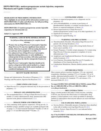
30001-30002 Instructions Layout 1 6/16/15 2:56 PM Page 3Note the following special instructions:usually come from a hardware store or auto parts store while 37 AN fittings are the ones supplied by Fitech and most speed shops.Remember that your system will be running at 58 PSI so consult aprofessional if you are not certain about this portion of your installation. Fitech does not recommend aluminum fuel lines EVER! Oryou can use the supplied EFI high pressure fuel hose that is suppliedin your Fuel Delivery Kit. Use the supplied push lock style hose ends only with the suppliedhose and vice versa. Intechanging hose ends and hose with otherbrands could cause leaks.VERY IMPORTANT NOTE: Your fuel tank must have a vent to preventpressure building up inside the tank. We recommend using the Fuel Command Center for all installations. A submerged pump is quieter and lasts longer. If using the Frame Mount Inline Fuel Pump, it should be mountedas close to the fuel tank as possible and also as low as possible. Itshould be within two to three feet of the tank. This type of pump isdesigned to pump, not draw, and works best when gravity fed. Only use hard fuel lines when using proper EFI rated flared fittings.Make sure that you remove ALL low pressure flex joints on factoryfuel lines and replace them with EFI rated fuel hose and use properflared connections and clamps. Be careful not to mix 45 and 37 AN fittings , they look similar but will not work together. 45 fittingsPlumbing Schematic for Fuel Command Center - Fuel Delivery Kit #40003Figure 1See separate Instruction Sheets that were provided witih this pump kit for complete detailsCap off Return PortAn inline pre-filter is not required. The Fuel Command Center contains an internal filterSupplied EFI Grade Fuel Hoseplus push-lock style hoseends, a fuel filter and fittings.FuelCommandCenterIN3-8 PSIFuel FilterStockFuelPumpThis replaces Stock Fuel LinePlumbing Schematic for External Inline Pump - Fuel Delivery Kit #40005Figure 2See separate Instruction Sheets that were provided with this pump kit for complete detailsReturn fuel Line to tankMust be mounted as low as the lowest pointof the Fuel Tank and within 2-feet of itFuel TankINFuel PumpPre-Fuel FilterPost-FilterNote: Before starting any installation, disconnect the ceptacle or a dry cloth. Do not allow raw fuel to collectground connection on the battery. Be very careful when on the engine as this is a fire hazard. Please observe exdisconnecting any fuel lines to let the fuel drain into a re- treme caution when working with the fuel system.Oxygen Sensor InstallationThe supplied O2 Sensor can be installed in either exhaustbank. The Sensor cable connects to one of the cablescoming out of the ECU on the throttle body.A. The ideal location for the Sensor is 2-4 inches after theexhaust collector. It must always be at least 18-inchesfrom the exhaust tip. Where short or open headers areutilized, install the sensor in the primary tube of the rearcylinder. Must be at least 8-inches from the exhaust port.It will not work on "zoomie" style headers.B.The sensor should be at least 10 above horizontal (seefigure #3) to allow condensation to run off. If this is notadhered to, the sensor is susceptible to water damage.C. Never position the sensor on the outside of a bend inthe tubing.3
30001-30002 Instructions Layout 1 6/16/15 2:56 PM Page 4false readings. ThisO2 SensorMinimumwill lead to poor engineof10 performance, including misfires, and theinability to properlyauto-tune the EFI. ConExhausttinued running of theCollector Figure 3system with an exhaust leak can create detonation and possible severe engine damage. Incorrect installation of the sensor, exhaustleaks, and any resulting damage is not covered by theFiTech manufacturer's warranty. Make sure your exhaustis leak-free. This is very important.D. The sensor must always be mounted ahead of any catalytic converter if so equipped.E. Drill a 7/8" diameter hole in the desired location.F. The supplied bung kit can either be welded in place orclamped onto the pipe. The clamp-on style works welland will not leak. If welded, make sure the bung is weldedcompletely all the way around and does not leak.G. Install the sensor into the bung. WARNING: Do notstart the engine wiithout the sensor cable connected tothe throttle body and the EFI system is fully operationalor damage will occur to the sensor.AIR LEAKS: It is important that no air leaks exist anywhere in the exhaust system between the sensor and theengine. Any exhaust leaks will cause the unit to receiveUse this 3/8" nipplefor brake booster.Throttle Body InstallationUse this 3/8" nipplefor PCV connection.Installing the throttle body is no different than replacingthe carburetor. Disconnect the throttle linkage and thefuel line. Remove the existing carburetor from the intakemanifold. Clean the gasket surface of the manifold.Use this 3/16" nipple for anyVacuum Ports: Before installing the throttle body deterun-ported vacuum need, suchmine the engine's need for vacuum accessories. Theas transmission modulator.FiTech throttle body has five vacuum ports includingported and manifold. These ports cover accessories suchas power brakes. There are three 3/16" male nipples andtwo 3/8" male nipple. If you need more vacuum connecCap this nipple or usetions than this, you can purchase vacuum tees and vacfor boost reference.See Figure 6Auum hose at your local auto parts store. See Figures 4,Figure 45, and 6 for location and use of various vacuum nipples.Throttle Body Installation:Roots type Superchargers Only:Place the supplied gasket ontoPlug the indicated vacuum port with a 1/16-NPTpipe plug which will thread directly into theUse this 3/16" nipple for portedthe manifold and place thehole. Use thread sealer. Connect boost refervacuum. (Distributor Advance)throttle body onto the gasket.ence hose to 3/16" nipple "A"For Unblown or Blow-through Only:The throttle body linkageUse nipple for boost gauge or boost reference.mustbe on the driver's side ofUse zip-tie to retain hose on nipple.the engine. Install the originalnuts and washers onto the fourcarburetor studs. Tighten to 16Figure 5lb. ft. of torque.The FiTech throttle body hasin the kit for the unused ports.AFigure 6four fuel ports. Three inlet andTwo plugs are installed in theone return. Any one of three can be the inlet. The outlet throttle body with one loose one in the kit. All three plugsport is marked with the word "Return." On a returnless will be used on returnless configurations and two wil besetup the outlet port is plugged. Three plugs are provided used when the system will have a return line.Coolant Temperature Sensor InstallationThe Temperature Sensor should be threaded into one ofthe ports in the intake manifold or cylinder head. The sensor threads are 3/8-NPT. Some manifolds have 1/2-NPTports and in this instance use supplied pipe reducer. Con-nect the Yellow/Black wire lead from the throttle body tothe sensor. Snap the connector into the sensor. UseTeflon tape or a quality pipe sealant on both the pipe reducer (if used) and on the temperature sensor.4
30001-30002 Instructions Layout 1 6/16/15 2:56 PM Page 5Wiring the EFI SystemThe supplied Harness "A" (see Figure 7) plugs into mating Connector "B" from the throttle body mounted ECU.See Figure 8. The various wires will need to be extendedto make required connections. See the Wire Chart onpage 6 which lists each wire used in the system and whatit connects to. It is strongly suggested that any wire extensions are made with the same gauge and color wireas is used in thesupplied HarFuseness. Make conBatterynections as aGround30soldered joint85 Relay 86rather than as a87Ign/AccCircuit Fusecrimped connec- Groundtion. Utilize aFan 1 - Yellow Wire, orshrink wrapped Fan 2 - Black WireSee Wire Chart on Pg. 6FanGroundsleeve coveringall connections. Fan CircuitWiring Harness"A"6-PinConnectorFigure 7Harness "A" plugs into connector "B" from throttle bodymounted ECU. See Figure 8 and page 6 Wiring Chart.Connects to 2-wire distributor when theTiming Control feature is used.Handheld ControllerconnectionsConnects to O2Sensor Cable6-Pin Connector "B"connects to Harness "A"shown in Figure 7Figure 8Connects to CoolantTemperature SensorYellow/Black WiresThe above photo shows all of the cables that are associ- Harness "A" which contains the main six wires used inated with the FiTech Go EFI System throttle body. The the system. The large coiled cable at top left connects tolarge cable at the bottom left connects to the supplied the supplied Oxygen Sensor cable.5
30001-30002 Instructions Layout 1 6/16/15 2:56 PM Page 6Wiring ChartThe Chart below lists all of the wires in the FiTech Go EFISystem. The wires are color coded and the wires that arepart of Harness "A" are all marked for where they go.There are six wires in Harness "A." Four of them are required connections and two are optional. One of the op-tional wires (Blue) is required when the Timing Controlfeature is being used. If Timing Control is not used, thenthe Black wire is used in place of the Blue wire. More detailed connection information (Figures 9 through 13) isprovided on later pages of these instructions.The Following Wires Are Used In All Systems (6-Pin Connecctor)Req./Opt.Wire ColorDescriptionRequiredRed (Large)Main power. Connect this wire directly to the positive ( ) terminal of the battery. This circuitneeds to be live even when the switch is off so that the self learning files are maintained. This isfused with a 25 amp fuse.RequiredYellow/BlackThis wire connects to the Engine Coolant Temperature SensorRequired only ifTiming Controlis not usedBlueThis is the tach input wire which triggers the system. It connects to the 12V Negative terminal ofthe coil. On HEI distributor it connects to the "Tach" terminal on the distributor cap or connectsto a tach output on a CDI box.Required only ifTiming Controlis usedBlackThis is the coil trigger wire. Connect this wire to the points wire on any external ignition CDI boxsuch as an MSD 6A or to negative coil post if not using a CDI box.RequiredOrange (Large)Fuel Pump circuit. This wire provides 12V to the fuel pump and connects to the positive ( ) terminal on the pump. No relay is required.Required02 HarnessThis cable from ECU connects to the Wide Band Oxygen Sensor harness.RequiredWiring Harness AThis connects to Connector "B" from ECU. See Figures 7 and 8 (Page 5).RequiredWhiteOn/Off - Connect this wire to a switched 12V circuit. Must be on during both "Key On" and "Cranking." DO NOT connect to the coil terminal when using an external CDI box such as an MSD 6A orany other CD ignition.OptionalUsed withTiming ControlViolet ( )Green (-)This is the input for a magnetic pickup, such as from an MSD distributor or any other magneticpickup two-wire distributor. This connection is only used in conjunction withthe Timing Control feature.OptionalYellowFan Circuit #1. This wire goes to the ground terminal of the fan relay.The Following Additional Wires Are Used In Power Adder Systems (4-Pin Connector)Req./Opt.Wire ColorDescriptionOptionalRed (Thin)Air ConditioningOptionalBlackFan Circuit #2. This wire goes to the ground terminal of the fan relay.OptionalWhiteNitrous "IN" Signal. This should receive 12V positive when Nitrous arming safety switch is activated.OptionalTanNitrous "OUT" signal. This is the relay ground for nitrous solenoids. Trigger wire cannot groundthe Nitrous solenoud directly. Must use relay.Wiring DiagramsOn the following five pages are various wiring diagramsthat address the most common ignition arrangementsthat will be found. Each diagram will show you thespecifics of how to wire your FiTech Go EFI System forthat particular ignition setup. Note that the FiTech Go EFItiming control feature cannot be utilized if you have a"ready-to-run" distributor or an HEI distributor. It willwork with most other aftermarket or stock distributorsbut in every instance the advance mechanism in the distributor must be locked so it cannot function when usingtiming control. Most aftermarket distributors provide instructions on how to lock the advance mechanism.6
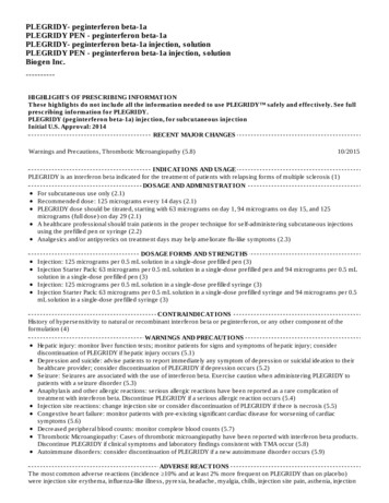
ure 11 is for an HEI distributor without timing control. Figure 12 is for a system with an external CDI box without timing control while Figure 13 is a CDIbox with timing control. And Figure 14 is with a conventional 2-wire distributor with timing control. One of these configurations will suit your vehicle.7Figure 9( )Ground(-)This harness andconnector is not usedVehicleBatteryYellow Wire (Connect to fan relay ground)Indicates a splice. It isrecommended that allsplices be made as asoldered connection.Electric FanInline Fuel Pumpshown. Connectionsare the same for theFuel Command CenterLarge Red WireLarge Orange WireWhite Wire6-PinConnectorFiTech Go EFI Throttle BodyCoil(-)This harness is a permanent connection toECU on the EFI throttle bodyBlack Wirenot usedto Negative Coil Post( )Existing connection between switch,distributor & coilBlue Wire - ConnectIgnition SwitchTiming Control cannot be used with Ready-to-Run DistributorOxygen SensorHandheld ControllerYellow/Black WireCoolant TemperatureSensorReady-to-Run DistributorWiring Connections for FiTech Go EFI System with Ready-to-Run Distributor w/o Timing ControlSelecting the correct wiring schematic: Review Figures 10 through 14 andselect the schematic that suits your particular application. Note that if youelect to use Timing Control you must select a suitable schematic. Figure 10shows how to connect a ready-to-run distributor without timing control. Fig-30001-30002 Instructions Layout 1 6/16/15 2:56 PM Page 7
8This harness andconnector is not usedVehicleBatteryGround(-)6-PinConnectorHEI DistributorThis harness is a permanent connection toECU on the EFI throttle bodyFiTech Go EFI Throttle BodyConnect GreenWire to "Tach"terminal on capBlack Wirenot usedBlue WireIgnition SwitchWhite WireOxygen SensorHandheld ControllerYellow/Black WireCoolant TemperatureSensorUse this wiring schematic if you are utilzing an HEI distributor without an Note that the Fitech EFI Timing Control feature cannot be used with this typeexternal CDI box, such as a MSD 6AL or similar aftermarket ignition box. of distributor. All other EFI features are compatible.Figure 10( )Yellow Wire (Connect to fan relay ground)Indicates a splice. It isrecommended that allsplices be made as asoldered connection.Electric FanLarge Red WireInline Fuel Pumpshown. Connectionsare the same for theFuel Command CenterLarge Orange WireTiming Control cannot be used with HEI DistributorWiring Connections for FiTech Go EFI System with HEI Distributor w/o Timing Control30001-30002 Instructions Layout 1 6/16/15 2:57 PM Page 8
9This harness andconnector is not usedVehicleBatteryGround(-)Black Wirenot usedCoilFiTech Go EFIThrottle BodyExternal CDI Box such as an MSD 6Al orsimilar aftermarket ignition boxThis harness is a permanent connection toECU on the EFI throttle bodyIgnitionSwitch6-PinConnectorWhite WireOxygen SensorHandheld ControllerYellow/Black WireCoolant TemperatureSensorConventional Two-WireDistributorUse this wiring schematic if you are utilzing a conventional two-wire distrib- nition box, and you will not be using the FiTech Timing Control feature. Seeutor with an external CDI box, such as a MSD 6AL or similar aftermarket ig- Figure 11 for this configuration with Timing Control.Figure 11( )Large Orange WireYellow Wire (Connect to fan relay ground)Indicates a splice. It isrecommended that allsplices be made as asoldered connection.Electric FanInline Fuel Pumpshown. Connectionsare the same for theFuel Command CenterLarge Red WireBlur Wire connectsto "tach out" wirefrom CDI BoxWiring Connections for FiTech Go EFI System with External CDI Box w/o Timing Control30001-30002 Instructions Layout 1 6/16/15 2:57 PM Page 9
10Connect to 2-wirepigtail on distributorVehicleBatteryGround(-)CoilFiTech Go EFIThrottle BodyExternal CDI Box such as an MSD 6Al orsimilar aftermarket ignition boxThis harness is a permanent connection toECU on the EFI throttle bodyIgnitionSwitch6-PinConnectorBlue Wirenot usedWhite WireOxygen SensorHandheld ControllerYellow/Black WireCoolant TemperatureSensorConventional Two-WireDistributorUse this wiring schematic if you are utilzing a conventional two-wire distrib- nition box, and you want to use the FiTech Timing Control. Note that yourutor with an external CDI box, such as a MSD 6AL or similar aftermarket ig- mechanical advance mechanism must be locked to use Timing Control.Figure 12( )Large Orange WireYellow Wire (Connect to fan relay ground)Indicates a splice. It isrecommended that allsplices be made as asoldered connection.Electric FanInline Fuel Pumpshown. Connectionsare the same for theFuel Command CenterLarge Red WireTo utilize FiTech TimingControl, the advancemechanism on the distributor must be lockedand inoperative.Black Wire connectsto "points input wirefrom CDI Box (may bea white wire)Wiring Connections for FiTech Go EFI System with External CDI Box with Timing Control30001-30002 Instructions Layout 1 6/16/15 2:57 PM Page 10
11VehicleBatteryGround(-)6-PinConnector( )CoilThis harness is a permanent connection toECU on the EFI throttle bodyIgnitionSwitchBlue Wirenot used(-)FiTech Go EFIThrottle BodyConnect Black Wire toNegative (-) post on CoilTo utilize FiTech TimingControl, the advancemechanism on the distributor must be locked andinoperative.Oxygen SensorHandheld ControllerYellow/Black WireCoolant TemperatureSensorConventional Two-WireDistributorUse this wiring schematic if you are utilzing a conventional two-wire distrib- ignition box, and you want to use the FiTech Timing Control. Note that yourutor without an external CDI box, such as a MSD 6AL or similar aftermarket mechanical advance mechanism must be locked to use Timing Control.Figure 13( )Large Orange WireYellow Wire (Connect to fan relay ground)Indicates a splice. It isrecommended that allsplices be made as asoldered connection.Electric FanLarge Red WireInline Fuel Pumpshown. Connectionsare the same for theFuel Command CenterWhite WireWiring Connections for FiTech Go EFI System with Conventional Distributor w/Timing Control30001-30002 Instructions Layout 1 6/16/15 2:57 PM Page 11
FiTech Fuel Injection TM Instruction Manual for the following Go EFI Systems 30001, 30002, 30004, 30012, 30061, 30062 & 30064 This Quick Start Manual is designed to get you up and . Data Com Cable (1) 8 gigabyte SD Card (Installed in Controller) (1) 3/8-NPT Reducer (1) 10mm Port Plug