Transcription
RMX 4050HD and RMX 5050User Manual*TD-000109-01*TD-000109-01 rev.F
Important Safety Precautions & Explanation of SymbolsWARNING!CAUTION: TO REDUCE THE RISK OF ELECTRIC SHOCK, DO NOT REMOVE THE COVER.NO USER-SERVICEABLE PARTS INSIDE. REFER SERVICING TO QUALIFIED PERSONNEL.The lightning flash with arrowhead symbol within an equilateral triangle is intended to alert the user to the presenceof uninsulated “dangerous” voltage within the product's enclosure that may be of sufficient magnitude to constitute arisk of electric shock to humans.The exclamation point within an equilateral triangle is intended to alert the user to the presence of important operating and maintenance (servicing) instructions in this manual.The lightning flashes printed next to the output terminals of the amplifier are intended to alert the user to the risk ofhazardous energy. Output connectors that could pose a risk are marked with the lightning flash. Do not touch outputterminals while amplifier power is on. Make all connections with amplifier turned off.1- Read these instructions.2- Keep these instructions.3- Heed all warnings.4- Follow all instructions.5- WARNING: To prevent fire or electric shock, do not expose this equipment to rain or moisture. Do not use this apparatus near water.6- Clean only with a dry cloth.7- Maximum operating ambient temperature is 50 C (122 F).8- Never restrict airflow through the device fan or vents. Please insure that the air intake and exhaust vents are unobstructed.9- Do not install near any heat sources such as radiators, heat registers, stoves, or other apparatus (including amplifiers) that produce heat.10- Do not defeat the safety purpose of the grounding-type plug. The grounding plug has two blades and a grounding prong. The third prong is provided for yoursafety. If the provided plug does not fit your outlet, consult an electrician for the replacement of the obsolete outlet. Do not cut off the grounding prong or use anadapter that breaks the grounding circuit. This apparatus must be properly grounded for your safety.11- Protect the power cord from being walked on or pinched, particularly plugs, convenience receptacles, and the point where they exit from the apparatus.12- This product is not equipped with an all-pole mains switch. To fully disconnect from the AC mains, the AC plug must be removed from the AC outlet or the appliance coupler (IEC block) must be removed from the amplifier module. Ensure either the AC line cord plug or the appliance coupler are accessible in case ofemergency disconnect requirement.13- Connect the unit only to a properly rated supply circuit.14- Reliable Earthing (Grounding) of rack-mounted equipment should be maintained.15- Use only attachments/accessories specified by QSC Audio Products, Inc.16- Unplug the apparatus during lightning storms or when unused for long periods of time.17- Refer all servicing to qualified service personnel. Servicing is required when the apparatus has been damaged in any way, such as power supply cord or plugis damaged, liquid has been spilled or objects have fallen into the apparatus, the apparatus has been exposed to rain or moisture, does not operate normally, orhas been dropped.18- The appliance shall not be exposed to dripping or splashing and no objects filled with liquids, such as vases, shall be placed on the apparatus.19- When installing equipment into rack, distribute the units evenly. Otherwise, hazardous conditions could be created by an uneven weight distribution.This amplifier has a serial number located on the rear panel.Please write this and the model number down and keep them for your records.Keep your purchase receipt. It is your proof of purchase.Serial Number:Date of Purchase:Purchased From:2 Copyright 2003, 2006, QSC Audio Products, Inc.QSC is a registered trademark of QSC Audio Products, Inc. “QSC” and the QSC logo are registered with the U.S. Patent and Trademark Office.Speakon is a registered trademark of Neutrik and the names of Neutrik products referenced herein are either trademarks and/or servicemarks of Neutrik . All trademarks are the property of their respective owners.
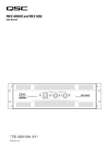
INTRODUCTIONThank you for purchasing this QSC power amplifier. Please read the following directions to obtain the best results.Key Features 2 channels XLR, TRS, and barrier strip screw terminal input connectors Speakon and binding post output connectors Each channel has independent Clip Limiter and Low Frequency Filter (30 or 50 Hz) Stereo, Bridge Mono, and Parallel modes of operation QSC reliability Complete amplifier protectionCONTROLS, CONNECTORS & FEATURES(RMX 4050HD shown, RMX 5050 similar)1- Power On indicator2- Power switch3- Cooling air exhaust vents4- Gain controls5- Clip and Signal indicators6- Protect mode indicator7- Barrier strip input connectors8- XLR input connectors9- TRS (1/4”) input connectors10- Mode switches and settings11- Cooling air inlet vents12- Speakon output connectors13- Binding post output connectors14- AC circuit breakers15- Serial number label16- IEC power inlet (power cord connector)UNPACKINGFactory packed carton contains: RMX amplifier User's manual Adhesive rubber feet (for non-rack mount applications) Rear rack ear mounting kit IEC-type detachable power cordUse the same type carton when shipping the amplifier.3
RACK MOUNTINGUse four screws and washers to mount the amplifier to theequipment rack rails. To use the amplifier outside a rack,attach the self-adhesive rubber feet to the bottom. Use therear rack ear support kit to support the rear of the amplifier forportable use.When installing equipment into a rack,distribute the units evenly. Otherwise,hazardous conditions may be created byan uneven weight distribution.COOLINGAir flow in QSC amplifiers: Cool air is drawn into therear of the amplifier by the cooling fan. Warm air exitsthe front of the amplifier.Air flows from the rack, into the back of the amplifier, and out the front. This keeps the rack cool. Thefan automatically runs faster when the amp is working hard.Do not block the front or rear air vents!AC MAINSConnect AC power to the IEC socket on the back ofthe amplifier. NOTE: Turn off the AC power switchbefore connecting AC power.The correct AC line voltage is shown onthe serial number label, on the rearpanel. Connecting to the wrong line voltage may damage the amplifier orincrease the risk of electric shock.SETTING THE MODE SWITCHESThe RMX 4050HD and RMX5050 have Modeswitches for Stereo, Parallel, or Bridge Mode. Additionally, each channel has independent Clip Limitingand Low Frequency (LF) Filtering.SETTING CLIP LIMITERSEach channel has a Clip Limiter with its own on-offswitch. The limiter only responds to actual clipping,and automatically compensates for load and voltagevariations. Clip limiting is generally recommended,especially to protect high frequency drivers.4Set switch to the right to use Clip Limiting.Switch 1 controls Channel 1.Switch 10 controls Channel 2.
SELECTING STEREO, PARALLEL, ORBRIDGE MODEThe amplifier can be set for normal Stereo operation, Parallel input Mode, or Bridge Mono Mode.Stereo Mode - Switches4, 5, 6 and 7 are all set tothe LEFT position.Stereo Mode- Each channel remains independent. Theamplifier may be used for two different signals.Parallel Mode - This setting connects both inputstogether. One signal feeds both channels. Each channel'sGain control and loudspeaker connection remain independent.Bridge Mode- This setting combines both channels intoa single channel with twice the output power. Use onlythe first channel's input and Gain control. Set the secondchannel's Gain control at minimum. The load must berated for the higher output power, and is connected asshown in the Outputs section.Do not connect different inputs to each side of achannel pair when operating in Parallel orBridge Mode.SETTING LOW FREQUENCY FILTERSEach channel has a 12dB per octave Low Frequency Filterto prevent cone overexcursion, making more power available for the loudspeaker’s rated frequency range. Thisreduces distortion and prevents amplifier overload.The Filter should only be turned off for driving subwoofers with special low frequency capability. Otherwise,unless you have filtering in the signal path preceding theamplifier, use the Low Frequency Filter. The loudspeaker’sdocumentation will specify the low frequency limit.BARRIER STRIP INPUTSEach channel has a balanced 3-terminal input. Wiring isconnected with simple hand tools, and inputs can bechanged quickly.Parallel Mode Switches 4, and 5, areset to the RIGHT position. Switch 6 and 7 areset to the LEFT position.Bridge Mode- Switches4, 5, 6,7 and 8 are all setto the RIGHT positionand Switch 10 is set tothe LEFT position.Each channel has its ownswitches for LF Filter on/off andfrequency selection.Channel 1 uses switches 2,3.Channel 2 uses switches 8,9.Switches 3 and 8 turn the LF Filter ON. Switches 2 and 9 select30Hz or 50 Hz.Balanced inputs: Strip thewires ¼ inch (6 mm) andconnect to the terminals asshown. Be sure to tightenthe screws firmly.The input impedance is 20k ohm balanced or 10k ohmunbalanced.Balanced connections are recommended to reduce AChum and interference, especially with long cable runs.Unbalanced connections may be suitable for short cables.The signal's source impedance should be less than 600ohms.If unbalanced connections are required, connect a jumperwire between the minus (-) terminal and the ground terminal. Then connect the input signal to the positive ( )terminal and the shield to the minus or ground terminal.Unbalanced inputs: Stripthe wire ¼ inch and connect a jumper wirebetween the minus (-) terminal and the ground terminal. Then connect theinput signal to the positive( ) terminal and the shieldto the minus or ground terminal, as shown. Be sureto tighten the screwsfirmly.5
XLR and TRS (1/4”) INPUTSEach channel has a balanced 3-terminal XLR and TRS input.Inputs are connected with standard cables and can bechanged quickly. Pinouts are marked on the rear panel andshown in the illustration.The input impedance is 20k ohm balanced or 10k ohm unbalanced.Balanced connections are recommended to reduce AC humand interference, especially with long cable runs. Unbalancedconnections may be suitable for short cables. The signal'ssource impedance should be less than 600 ohms.Unbalanced TRS connectors (2-terminal) automatically connect the minus (-) terminal to ground when inserted.OUTPUTSWiring connections are shown on the back of the chassis.BINDING POST OUTPUTSStereo and Parallel Mode: Wire as shown by loudspeaker symbols 1 and 2.Bridge Mode: Wire as shown by Bridge Mono loudspeakersymbol.SPEAKON OUPTPUTSEach channel accepts a normal 2-wire cable. In addition, Channel 1 accepts 4-wire cables for single cable stereo or bi-ampconnection.OUTPUT TERMINAL SAFETY WARNING! Do nottouch output terminals while amplifier power is on.Make all connections with amplifier turned off. Riskof hazardous energy!Stereo and Parallel Mode- Connect each loudspeaker to itsown channel of the amplifier, as shown on the left side of thechassis label. The Mode configuration switches must be setfor Stereo or Parallel Mode.Bridge Mode- Bridge Mode configures the channel pair todrive a single audio circuit. The Mode configuration switchesmust be set for Bridge Mode.Connect the load as shown on the right side of the bindingposts or to the left on Channel 1’s Speakon. 4 ohms is the minimum impedance for Bridge Mode use.Do not use less than 4 ohm load in Bridge Mode!Note polarity of connection for Bridge Mode.OUTPUT WIRING WARNING:CLASS 2 WIRING SHALL BE USED.FOR BRIDGED MONO MODE, CLASS 3 WIRINGSHALL BE USED.6
LED INDICATORSThe LED indicators can be used to monitor system operation and identify common problems.Indicators and Gain controls.POWER: A single green indicator, on left side of AC power switch.Normal indication: AC switch ON: indicator will illuminate.If no indication: Check AC power cord and AC outlet. Check rear panel circuit breakers.CLIP: red, to the left of each Gain control.Normal indication: illuminates whenever the amplifier is driven beyond full power. The LED’s brightness indicates theamount of distortion. Distortion that causes only brief flashing may not be audible.During muting, the indicator fully illuminates. This occurs during normal “On-Off” muting.Abnormal indication: Bright red illumination while the amp is being used indicates either thermal muting or a shorted output. If the amplifier overheats, the fan will run at full speed, and operation should resume within one minute. Allow the fan torun, and make sure the amplifier ventilation is adequate. A shorted or overloaded output circuit will cause excessive Clip flashing and possible overheating. If distortion is audible without a Clip indication, the problem is either before or after the amplifier. Check for damagedspeakers or overloaded signal source. The amplifier Gain control should be in the upper half of its range to prevent input overload.SIGNAL: yellow, to the left of each Gain control.Normal indication: illuminates when the input signal exceeds -35 dB. As signal approaches full power, the indicator willilluminate continuously.If no indication: check Gain settings and increase Gain if necessary. Check input connections and audio source for signal. Ifthe Clip indicator illuminates with little or no Signal indication, check the output wiring for shorts.Abnormal indication: If the Signal indicator illuminates with no signal input, there may be system oscillations or someother malfunction. Disconnect the load and fully reduce the Gain. If the signal indicator remains on, the amp may need servicing.PROTECT: red, on the right side of Gain control group.Normal indication: illuminates when the amplifier goes into protective muting. Under normal operation, this indicator willnot be illuminated.Abnormal indication: If the Protect indicator illuminates, the amplifier is in protective muting. Leave the Power On to allowthe fan to cool the amplifier. Check the rear panel circuit breakers; if either is tripped, reset it by pushing on the center of thecontrol. When the amplifier has cooled sufficiently, the Protect indicator will extinguish and normal operation will resume.Note! If both rear panel circuit breakers are tripped, the Protect indicator will not be illuminated.7
GAIN CONTROLSTurn the Gain controls clockwise to increase Gain and counterclockwise to decrease Gain. At the maximum setting, the voltage Gain of the amplifier is 36 dB. The RMX 4050HD willproduce 800 watts into 8 ohms when driven with a 1.26V inputsignal. The RMX 5050 produce 1050 watts into 8 ohms whendriven with a 1.42V input signal.The Gain controls are marked in dB of gain. Settings shouldnormally be made within the upper half of the adjustmentrange. The range below 22 dB should not be used for normalprogram levels, as the input headroom could be exceeded, butcan be used for testing at reduced levels. At the minimum setting, the signal is completely cut off.Continuous operation at high power may trigger thethermal protection circuitry, shutting down theamplifier and fully illuminating the Protect indicator. Operation will resume after the amplifier hascooled down sufficiently.Note! If both rear panel circuit breakers aretripped, the Protect indicator will not be illuminated.8Gain controls and indicators.
SPECIFICATIONSOutput Circuit Typecomplementary bipolar output with multi-step high efficiency circuitOutput Power in wattsRMX 4050HDRMX 5050FTC: 20 Hz to 20 kHz, 0.1% THD 8 ohmsboth channels driven4 ohms2 ohms80013001600105016002000EIA: 1 kHz, 0.1% THDboth channels driven8 ohms4 ohms2 ohms, 1% THD85014002000110018002500Bridged Modeat 0.1% THD8 ohms, 20 Hz to 20 kHz8 ohms, 1 kHz4 ohms, 1 kHz, 1% THD2600280040003200360050001.25 Vrms1.42 VrmsInput Sensitivity for rated power into 8 ohmsInput Impedance20 k ohm balanced, 10 k ohm unbalancedVoltage Gain64x (36 dB) for 8 ohm loadDynamic Headroom at 4 ohms2 dBDistortion, SMPTE 0.02%Frequency response at 1 watt20 Hz to 20 kHz, 8 ohms, LF Filter bypassed: 0, -1 dB5 Hz to 50 kHz, 8 ohms, LF Filter bypassed: 0, -3 dBDamping Factor 250, 8 ohm loadNoise (unweighted)100 dB below rated output from 20 Hz to 20 kHz, 8 ohm loadControlsFront Panel- AC power switch, CH1 Gain control, CH2 Gain controlRear Panel- 10-pole DIP switch featuring LF Filter on/off, LF Filter 30/50 Hz, Clip Limiter on/off controlsfor each channel and switches for selecting Stereo, Parallel, or Bridge Mode. Push-button circuitbreaker for each channel.ConnectorsInputs: XLR female, TRS (1/4-inch), and barrier-strip screw terminals provided for each channelOutputs: binding posts and Speakon outputs (CH1 Speakon wired for bi-amp connection)LED IndicatorsPower “on”, green; Protect, red; Signal -35 dB, yellow (1 each channel); Clip, red (1 each channel)Coolingcontinuously variable speed fan, rear to front airflowAmplifier Protectionshort circuit, open circuit, thermal, ultrasonic, and RF protection;stable into reactive/mismatched loadsLoad Protectionturn-on and turn-off muting, DC fault output crowbarPower Requirements100, 120, or 240 Volts AC ( 10%) 50-60 HertzCircuit BreakersRMX 4050HD: two (one for each channel): 100 and 120 V models: 15 amp / 230 V models: 8 ampRMX 5050: two (one for each channel): 100 and 120 V models: 20 amp / 230 V models: 10 ampAC Connectiondetachable 3-conductor grounded, Class 1 typeCurrent Consumption at 120V (in amperes) at typical/full/maximum output power (idle current 1 amp)8 ohms4 ohms2 ohmsRMX 4050HDtypical 6.4, full 12.5, maximum 25.5typical 10.0, full 20.1, maximum 42.2typical 14.5, full 30.6, maximum 65.7RMX 5050typical 8.7, full 17.0, maximum 34.4typical 13.9, full 26.9, maximum 56.4typical 18.9, full 38.0, maximum 84.7Current Consumption Notes:Typical- 1/8 power, pink noise, represents typical program with occasional clipping. Full- 1/3 power, pink noise, represents severe program with heavy clipping. Maximum- continuous sine wave at 1% clipping.AC Inlet:IEC 6032 C13IEC 6023 C19Supplied Cord Set120V: 8ft (2.5m), NEMA 5-15 plug120V: 8ft(2.5m), NEMA 5-20 plug230V: 8ft(2.5m), CEE7/7 plug230V: 8ft(2.5m), CEE7/7 plugWeight68 lb. (30.8 kg) net, 77 lb. (34.9 kg) shipping75 lb. (33.1 kg) net, 87 lb. (37.2 kg) shippingDimensions19.0” wide x 5.2” (3RU) high x 15.9” deep (482x132x404mm)Specifications are subject to change without notice.9
WARRANTY INFORMATION & HOW TO CONTACT QSCWarranty (USA only; other countries, see your dealer or distributor)DisclaimerQSC Audio Products, Inc. is not liable for any damage to speakers, or any other equipment that is caused by negligence or improperinstallation and/or use of this amplifier product.QSC Audio Products 3 Year Limited WarrantyQSC Audio Products, Inc. (“QSC”) guarantees its products to be free from defective material and / or workmanship for a period ofthree (3) years from date of sale, and will replace defective parts and repair malfunctioning products under this warranty when thedefect occurs under normal installation and use - provided the unit is returned to our factory or one of our authorized service stations via pre-paid transportation with a copy of proof of purchase (i.e., sales receipt). This warranty provides that the examinationof the return product must indicate, in our judgment, a manufacturing defect. This warranty does not extend to any product whichhas been subjected to misuse, neglect, accident, improper installation, or where the date code has been removed or defaced. QSCshall not be liable for incidental and/or consequential damages. This warranty gives you specific legal rights. This limited warrantyis freely transferable during the term of the warranty period.Customer may have additional rights, which vary from state to state.In the event that this product was manufactured for export and sale outside of the United States or its territories, then this limitedwarranty shall not apply. Removal of the serial number on this product, or purchase of this product from an unauthorized dealer,will void this limited warranty.Periodically, this warranty is updated. To obtain the most recent version of QSC's warranty statement, please visit www.qscaudio.com.Contact us at 800-854-4079 or visit our website at www.qscaudio.com.Mailing address:QSC Audio Products, Inc.1675 MacArthur BoulevardCosta Mesa, CA 92626-1468 USATelephone Numbers:Main Number (714) 754-6175Sales & Marketing (714) 957-7100 or toll free (USA only) (800) 854-4079Customer Service(714) 957-7150 or toll free (USA only) (800) 772-2834Facsimile Numbers:Sales & Marketing FAX(714) 754-6174Customer Service FAX(714) 754-6173World Wide e@qscaudio.comQSC Audio Products, Inc. 1675 MacArthur Boulevard Costa Mesa, California 92626 USA“QSC” and the QSC logo are registered with the U.S. Patent and Trademark Office. 2003, 2006 QSC Audio Products, Inc.
(RMX 4050HD shown, RMX 5050 similar) UNPACKING Factory packed carton contains: RMX amplifier User's manual Adhesive rubber feet (for non-rack mount applications) Rear rack ear mounting kit IEC-type detachable power cord Use the same type carton when shipping the amplifier. 1- Power On indicator 2- Power switch 3- Cooling air .