Transcription
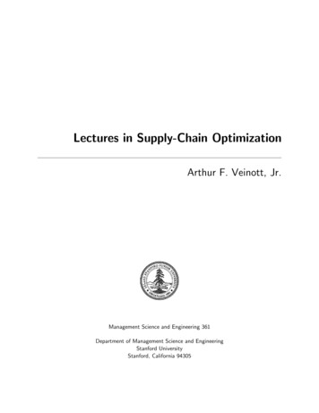
50505150R9850 Price IndexEnergy Chain System E4/4Series 5050/5150/R98503.15”Features & BenefitsKMA mounting brackets with attachment points onSeries 5050Series 5150all sidesCrossbars on Energy Chains are removable alongSeries R9850Special Features / Optionsboth radiiHinged, snap-open, removable lids along outerradius of Energy TubeSide-mounted - unsupportedLateral glide surfaces for side-mounted operationStrain relief elements can be integrated with theESD classification:Electrically conductiveESD/ATEX version upon requestmounting bracketHigh torsional rigidityHigh torsional rigidityWide, rounded plastic crossbars - cable friendlyClosed and open styles can be combinedAssembly TipsHigh side-mount stability due to undercutNumerous interior separation possibilitiesEnergy Chain also available with reverse bending radiiOpening Energy Chains : Remove crossbars and clips - Insert screwdriver into theslot, push down, release by lever actionRemove lids/bottoms (Energy Tubes) - Insert screwdriver into the slot, release bylever actionOther Installation MethodsVertical, hanging 394 ft (120 m)Vertical, standing 19.69 ft (6 m)Side-mounted, unsupp. 9.84 ft (3 m)Rotary requires further calculationUsage Guidelines If subject to high torsional forces For side-mounted applicationsinvolving long unsupported lengths If subject to very dirty or dustyenvironmentsRol E-Chain Series5050R/9850R availableupon requestOrder Example: Complete Energy Chain If a simpler low-cost solution isrequired‰ Series 15050/R19850 When very long travels or highadditional loads are involved‰ Series 5050HD/R9850HD6.113energy chain configuratorPlease indicate chain length or number of links. Example:16.4 ft (5 m) 5050-30-300-0Energy Chain With 2 separators 511 assembled every 2nd linkInterior Separation1 Set 505000-30-12PMounting Bracket3.15”
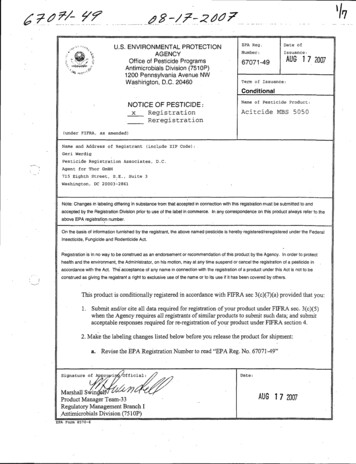
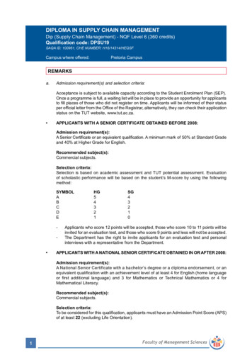
Fill weight lbs/ftenergy chain configuratorShort travel, unsupported length FLB unsupported with permitted sag FLG unsupported with straight upper run47.0340.3233.60Short Travels UnsupportedFLB26.8820.16FLG13.44UnsupportedEnergy Chains positivefeaturecamber over short travels.This must be accounted forwhen specifying the clearance height. Please refer toInstallation dimensions forfurther details.6.72Further information ‰ Design, Chapter 14.03FLG1.341.01HHF.67.34FLB003.28 6.56 9.84 13.12 16.41 19.691.64 4.92 8.20 11.48 14.76 18.05Unsupported length in ft FLB / FLGS (FLG)LegendS S (FLB)6.56013.12 19.69 26.25 32.81 39.37Length of travelR Bending radiusLength of travel S in ftH Nominal clearanceSheightS/2DD Overlength EnergypositionHF Required clearancePitch per link: 3.58” (91 mm)HRI Trough inner heightFor center mount applications:H2 *Mounting heightChain length /2 KsD2 Overlength - longtravels, glidingK2 *Add-on*If the mounting bracketlocation is set lowerThe required clearance height: HF H 2.36 in. (60 mm) (with 2.02 lbs/ft (3 kg/m) fill weight.Please consult igus if space is particularly restricted.5.91 (150)7.87 (200)heightLinks per ft (m): 3.35 (11)3.58(91)R π R safety bufferK4.25(108)Fixed EndHRHF H 2.36 (60)H - 4.25 (108)Chain radius in finalMoving End50505150R98509.84 (250)11.81 (300)13.78 (350) 15.75 (400)23.62 (600) 25.59 (650)39.37 (1000)H -0 2516.06 (408) 20.00 (508) 23.94 (608)27.87 (708)31.81 (808)35.75 (908) 43.62 (1108) 47.56 (1208) 51.50 (1308) 55.43 (1408)19.68 (500)21.65 (550)82.99 (2108)D11.61 (295) 13.58 (345) 15.55 (395)17.52 (445)19.49 (495)21.46 (545)45.08 (1145)K25.79 (655) 32.09 (815) 38.19 (970) 44.29 (1125) 50.59 (1285) 56.69 (1440) 69.09 (1755) 75.20 (1910) 81.50 (2070) 87.60 (2225) 128.15 (3255)25.39 (645)27.36 (695)29.33 (745)For long travels with lowered mounting heightFor center mount applications:Long travel lengths from 32.8 ft.(10m) to max. 1,312 ft. (400m)Chain length: 31.30 (795)3.15”PDF: www.igus.com/e-chain-pdfsSpecs/CAD/RFQ: www.igus.com/e-chainsRoHS info: www.igus.com/RoHSEnergy Chain System E4/4Series 5050/5150/R9850Installation DimensionsLong Travels Gliding/2 K2sSD2S/2Fixed endK2RHRIMoving endH2S/2Guide trough with glide barGuide trough without glide barIf the unsupported length isexceeded, the EnergyChain /Tube must glide onitself. This requires a guidetrough.Design, Chapter 1Total length of guide troughR5.91 (150)7.87 (200)9.84 (250) 11.81 (300)H29.53 (242)9.53 (242)9.53 (242)15.75 (400)19.68 (500)21.65 (550)9.53 (242)9.53 (242)9.53 (242)9.53 (242)37.40 (950) 47.24 (1200) 61.02 (1550) 66.93 (1700)85.63 (2175)23.62 (600) 25.59 (650) 39.37 (1000)9.53 (242)--93.11 (2365) 101.57 (2580)--35.83 (910) 50.16 (1274) 64.49 (1638) 78.82 (2002) 96.73 (2457) 107.48 (2730) 136.14 (3458) 143.31 (3640) 175.55 (4459)--D2 25 21.65 (550) 31.50 (800)K213.78 (350)9.53 (242)For support of the lower run, see Chapter 9 for the Support Tray tool kitTechnical DataSpeed / acceleration FLGmax. 65.6 ft/s (20 m/s) / max. 656 ft/s2 (200 m/s2)Speed / acceleration FLBmax. 9.84 ft/s (3 m/s) / max. 19.69 ft/s2 (6 m/s2)Gliding speed / acceleration (maximum)max. 32.8 ft/s (10 m/s) / max. 164 ft/s2 (50 m/s2)Material - permitted temperatureigumid G / -40 F (-40 C) up to 248 F ( 120 C)Flammability Class, igumid GVDE 0304 IIC UL94 HBF Details of materialproperties‰ Chapter 16.114
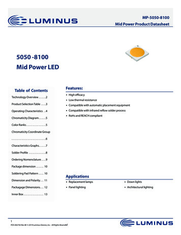
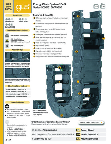
Energy Chain System E4/4Series 5050/5150/R9850energy chain configuratorSeries 5050 - Energy Chain with crossbars every linkBaBiSeries50504.25 (108)2.91max. 3.15 (80)igus Energy ChainSystem 50505150R9850R Crossbars every linkFor use with rigid hydraulichosesFor particularly demandingapplicationsCan be opened from bothsidesPart Number Structure5050- 30- 300- 0Color - BlackBending radiusWidthSeries6.115BaBi4.25 (108)Series51503.15 (80)2.91max. R Crossbars every other link Standard configurationFor nearly every situationCan be opened from bothsidesEasy assemblyStableCost-effectivePart Number Structure5150- 30- 300- 0Color - BlackBending radiusWidthSeriesSeries R9850 - fully enclosed Energy TubeBaBi4.25 (108)2.91max.SeriesR9850 3.15 (80) R Fully enclosedExcellent cable and hoseprotection against dirtProtection against hot chipsup to 1652 F (900 C)Lids along inner radius arecompletely removableLids along the outer radiusare single-sided, snap open,hinged on one side as well ascompletely removablePart Number Structure9850- 30- 300- 0Color - BlackBending radiusWidthSeriesEnergy Chain as separate parts, links and side platesRight side link*, single part - Part No. 5050-02- RBiSMoving EndRFixed End3.58(91)Single bottom, Energy Tube - Part No. 886- BiBiLeft side link*, single part - Part No. 5050-01- RBi*View from the fixed point of the Energy Chain /Energy TubeHS/2HF H 2.36 (60)DH - 4.25 (108)Single crossbar, Energy Chain - Part No. 450- BiBiSingle lid, Energy Tube - Part No. 885- BiBi4.25(108)Internet: http://www.igus.comemail: sales@igus.comQuickSpec: http://www.igus.com/quickspecTelephone 1-800-521-2747Fax1-401-438-7270Series 5150 - Energy Chain with crossbars every other link
Energy Chain System E4/4Series 5050/5150/R9850 energy chain configuratorSupplement part number with required radius. Example: 5050-30- 300 -0Pitch: 3.58 in. (91mm) per link links/ft(m) 3.35 (11)50505150R9850BiBa50505150R9850in. (mm)in. (mm)lbs/ft (kg/m)lbs/ft (kg/m)lbs/ft (kg/m)-01.97 (50)3.94 (100) 3.78 (5.63) 3.78 (5.62)–-02.56 (65)4.53 (115) 3.83 (5.70) 3.82 (5.68)–9850-07--0*2.95 (75)4.92 (125) 3.89 (5.79) 3.83 (5.70) 4.19 (6.24)-03.43 (87)5.39 (137) 3.96 (5.89) 3.87 (5.76)–5150-10-9850-10--03.94 (100)5.91 (150) 4.00 (5.96) 3.89 (5.79) 4.38 (6.52)5050-11-5150-11--04.41 (112)6.42 (163) 4.09 (6.09) 3.93 (5.85)–5050-12-5150-12-9850-12--04.92 (125)6.89 (175) 4.14 (6.16) 3.96 (5.89) 4.63 (6.89)5050-13-5150-13--05.39 (137)7.40 (188) 4.23 (6.29) 4.00 (5.95)–5050-15-5150-15-9850-15--05.91 (150)7.87 (200) 4.27 (6.36) 4.02 (5.98) 4.92 (7.32)5050-16-5150-16--06.38 (162)8.39 (213) 4.35 (6.47) 4.06 (6.04)–5050-17-5150-17--06.89 (175)8.86 (225) 4.42 (6.58) 4.09 5050-42-CrossbarsEvery 07-5050-08-5150-08-5050-10-TubeVersion-07.36 (187)9.37 (238) 4.50 (6.69) 4.13 (6.15)–-07.87 (200)9.84 (250) 4.51 (6.71) 4.14 (6.16) 5.30 (7.89)5150-21--08.35 (212)10.35 (263) 4.58 (6.82) 4.18 (6.22)–5150-22--08.86 (225)10.83 (275) 4.63 (6.89) 4.20 (6.25)–9850-20--09.33 (237)11.34 (288) 4.72 (7.02) 4.24 (6.31)–9850-25--09.84 (250)11.81 (300) 4.78 (7.11) 4.27 (6.36) 5.79 (8.61)-010.31 (262)12.32 (313) 4.83 (7.19) 4.30 (6.40)–9850-27-010.83 (275)12.80 (325) 4.91 (7.30) 4.34 (6.46) 5.93 (8.82)-011.30 (287)13.31 (338) 4.93 (7.33) 4.35 (6.47)–9850-30--011.81 (300)13.78 (350) 5.07 (7.55) 4.42 (6.58) 6.23 (9.27)5150-31--012.28 (312)14.29 (363) 5.09 (7.58) 4.43 (6.60)–5150-32--012.79 (325)14.76 (375) 5.13 (7.63) 4.45 (6.62)–-013.27 (337)15.28 (388) 5.25 (7.81) 4.51 (6.71)–-013.78 (350)15.75 (400) 5.35 (7.96) 4.56 (6.79) 6.73 (10.02)5150-36--014.25 (362)16.26 (413) 5.36 (7.97) 4.57 (6.80)–5150-37--014.76 (375)16.73 (425) 5.37 (7.99) 4.57 (6.80)–9850-35--015.24 (387)17.24 (438) 5.42 (8.07) 4.60 (6.84)–-015.75 (400)17.72 (450) 5.56 (8.27) 4.66 (6.94) 7.38 (10.98)5150-41--016.22 (412)18.23 (463) 5.66 (8.43) 4.72 (7.02)–5150-42--016.73 (425)18.70 (475) 5.77 (8.58) 4.77 (7.10)–5050-43-5150-43--017.20 (437)19.21 (488) 5.81 (8.65) 4.79 (7.13)–5050-45-5150-45--017.72 (450)19.69 (500) 5.85 (8.71) 4.81 (7.16)–5050-46-5150-46--018.19 (462)20.20 (513) 5.87 (8.73) 4.82 (7.17) 7.69 (11.44)5050-47-5150-47--018.70 (475)20.67 (525) 5.96 (8.87) 4.87 (7.24)–5050-48-5150-48--019.17 (487)21.99 (538) 5.97 (8.88) 4.88 (7.26)–5050-50-5150-50--019.69 (500)21.65 (550) 6.05 (9.00) 4.91 (7.30)–5050-51-5150-51--020.16 (512)22.16 (563) 6.06 (9.02) 4.92 (7.32)–5050-52-5150-52--020.67 (525)22.64 (575) 6.09 (9.06) 4.93 (7.34)–5050-53-5150-53--021.14 (537)23.15 (588) 6.20 (9.22) 4.98 (7.41)–5050-55-5150-55--021.65 (550)23.62 (600) 6.52 (9.70) 5.15 (7.66)–5050-60-5150-60--023.62 (600)25.59 (650) 6.65 (9.90) 5.21 (7.76)–9850-40-9850-46-PDF: www.igus.com/e-chain-pdfsSpecs/CAD/RFQ: www.igus.com/e-chainsRoHS info: www.igus.com/RoHSPart Number.CrossbarsEvery linkChoose from the radii below for all of the above sizesR adius (mm)Example: 5050-30- 300 -01502002503003504005005506006501000R5.91 (150)7.87 (200)9.84 (250)11.81 (300)13.78 (350)15.75 (400)19.68 (500)21.65 (550)23.62 (600)25.59 (650)39.37 (1000)H -0 2516.06 (408)20.00 (508)23.94 (608)27.87 (708)31.81 (808)35.75 (908)43.62 (1108) 47.56 (1208) 51.50 (1308) 55.43 (1408) 82.99 (2108)D11.61 (295)13.58 (345)15.55 (395)17.52 (445)19.49 (495)21.46 (545)25.39 (645)K25.79 (655)32.09 (815)38.19 (970)44.29 (1125)50.59 (1285) 56.69 (1440) 69.09 (1755) 75.20 (1910) 81.50 (2070) 87.60 (2225) 128.15 (3255)** This radius is not available for the R9850 Series*Removable lid only, no hinged option27.36 (695)29.33 (745)31.30 (795)45.08 (1145)0 Standard color black. For other colors see Chapter 1For wider chains see page 6.49. For large diameter hoses see page 6.496.116
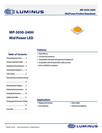
igus Energy ChainSystem 50505150R9850Vertical separators are used if a vertical subdivision of the Energy Chain interior is required. By standard,vertical separators are assembled every other Energy Chain link.NOTE: Observe a lateral spacing of at least 1.30 in. (33mm) for Energy Tubes and .63 in. (16mm) forEnergy Chain . There is no minimum spacing needed for side platesEnergyChain EnergyTube511A518511STANDARD415-X514.12 (3)VerticalseparatorLocking.16 (4)separator504.87(22).16 (4)separatorInternet: http://www.igus.comemail: sales@igus.comQuickSpec: r.87(22).12 (3).45(11.5)501A.14 (3.5).71(18)min. 1.26”32 mmVertical separatorUnassembledPart No. 501AssembledPart No. 511Locking separator(chain only)UnassembledPart No. 504AssembledPart No. 514Locking separator(chain only)UnassembledPart No. 508AssembledPart No. 518Asymmetrical separator(chain only)UnassembledPart No. 501AAssembledPart No. 511ASpacer(chain only)Spacers405-XX511 Standard separator 501 for Energy Chains andEnergy TubesThis separator offers safe stability due to its widebase design, also when used with thick cables orhoses. Locking separator 504 for Energy Chains This separator features increased retention force forapplications exposed to very high humidity andextreme loads. If locking separators are used, theEnergy Chain is more difficult to open. Locking separator 508 for Energy TubesThis separator is used for applications that areexposed to extremely high humidity. The clamp atthe side serves to uniformly align the separators. Inorder to avoid destroying the separators whenopening the Energy Chain , make sure allseparators are identically aligned. Asymmetrical separator 501A for Energy Chains This separator features an (18mm) base. It can beused in combinations between spacers of differentwidths and vertical separators in side mountedapplications. NOTE ON SPACERSVertical separators are adjustable, but can be fixedin position by means of a spacer. Spacers are mostoften necessary for side mounted applications.The available inner height is reduced by .08” (2mm)per spacer (for example if one spacer is placed oneither side of the separator, the overall inner heightis reduced by .16” (4mm). To avoid this, place thespacers on the outside of the opening crossbar(not for long travels).71(18)501Locking6.117energy chain configuratorOption 1: Vertical separators and spacersmin. 0.63”16 mmTelephone 1-800-521-2747Fax1-401-438-7270Energy Chain System E4/4Series 5050/5150/R9850Interior Separation XXUnassembledPart No. 405-XXAssembledPart No. 415-XXXX width of the spacerSpacers available in the following sizes:Part No.Part No.Unassembled Assembledin.(mm)405 -10415 -10.39”(10)405 -15415 -15.59"(15)405 -20415 -2079”(20)405 -30415 -301.18”(30)405 -40415 -401.57”(40)
Energy Chain System E4/4Series 5050/5150/R9850Interior Separation energy chain configurator50505150R9850Option 2: Shelves Vertical separator 503This component is used to form the basicpattern of a shelf system.Locking vertical separator 507This separator features increased retentionforce for applications exposed to very highhumidity and extreme loads. The extraretention force is achieved by asymmetricclaws for the crossbar. Take care to ensureproper alignment.421-X.16(4)UnassembledPart No. 502AssembledPart No. 512.20(5)520Side plate519515513Side plate502Vertical separator.31(8).16 (4)UnassembledPart No. 503AssembledPart No. 513Locking vertical separator.83(21)Locking vertical separator 510This separator is slotted and able to becombined with shelves. For Energy Chains only.31 (8)Slotted separators 505These are used for very complexsubdivisions. However, they cannot beretrofitted into an existing separation systemwithout removing the shelves first.14 (3.5)Slotted separator 509This separator can be retrofitted into anexisting interior separation system withoutremoving the shelves, as long as theseshelves fit into any of the 7 middle slots517.12 (3).39(10)503Locking verticalPart No. 507separatorAssembledPart No. 517507Locking verticalUnassembledPart No. 510separatorAssembledPart No. 520510Slotted separators, closed.24(6)5UnassembledLocking vertical separator.83(21)Vertical separatorClosed slottedUnassembledPart No. 505separatorAssembledPart No. 515505Slotted separators, openOpen slottedUnassembledPart No. 509separatorAssembledPart No. 519509Shelves 420-XXThese components form the basic pattern of a shelf system. Shelves of various widths can be arranged at 7 different heights in .28”(7mm) incrementsUsablePart No.Part No.UsablePart No.Part No.Width XWidthUnassembled AssembledWidth XWidthUnassembled Assembledin. (mm)in. (mm)in. (mm)in. (mm)X- .31 (8).71(18).39(10)420-18421-182.95 (75)2.64 (67)420-75.91(23).59(15)420-23421-233.46 (88)3.15 (80)420-88421-88.98(25).67(17)420-25421-253.94 (100)3.62 (92)420-100421-1001.10 (28).79(20)420-28421-284.92 (125)4.61(117)420-125421-1251.30 (33).98(25)420-33421-335.91 (150)5.59(142)420-150421-1501.69 (43)1.38 (35)420-43421-436.89 (175)6.57(167)420-175421-1751.97 (50)1.65 (42)420-50421-507.36 (187)7.05(179)420-187421-1872.44 (62)2.13 (54)420-62421-627.87 (200)7.56(192)420-200421-200Rollclip - minimizes abrasion of particularlysensitive hoses or cables in an Energy Chain .The integrated rollers compensate for relativemovement between the chain and the hose orcable. This reduces the abrasion of the hosesor cablesPDF: www.igus.com/e-chain-pdfsSpecs/CAD/RFQ: www.igus.com/e-chainsRoHS info: www.igus.com/RoHS Side plates 502This component is used to form the basicpattern of a shelf system.28 (7).28 (7).77(19.5)1.57 (40)512 .28 (7).83(21)Energy Chains and Energy Tubescan be subdivided both verticallyand horizontally using the variousinterior separation elements.‰ Design, Chapter 1 for bled Part No. 489-27.35(9)AssembledPart No. 490-27276.118
50505150R9850 Energy Chain System E4/4Series 5050/5150/R9850Special Accessoriesenergy chain configuratorExtension links - for extremely wide Energy Chains up to 9.84 ft (3m)Bi 2.79(20)We strongly recommendon-site consultation with anigus technician for individualadvice regarding mountingbrackets, guide troughs andother design details.Bi 1 .98 (25)ø.43(11)5050-Bi1/Bi2/Bi3- R -0Bi 3(1)Bi 11.38 (35)Telephone 1-800-521-2747Fax1-401-438-7270Part number example forEnergy Chain 5050-10/20/10- 200 -03.13(79.5) .04 For applications in which particularly high fill weights necessitate extremely wide Energy Chains (upto 118” (3000 mm)The extension link design allows virtually limitless side-by-side attachment of chainsThe unsupported length of a chain can be increased when additional loads are requiredExtension links can be used with Energy Chains , Energy Tubes or a combination of bothThey are suitable for unsupported and gliding applications in a guide troughEnergy Chains with extension links are attached with KMA or steel mounting brackets.1.0025.5)igus Energy ChainSystem Bi 2 .87 (22)Bi 3 .98 (25)Bi 1 .98 (25) Bi 2 .87 (22) Bi 3 .98 (25) .12 (3)[Bi 1 .98 (25) Bi 2 .87 (22) Bi 3 .98 (25)] .87 (22) .12 (3)Extender crossbars - For careful guiding of large diameter cables and hoses Intended for cables and hoses with a maximum outer diameter of 10.63 in. (270 mm).Can be attached along either the inner or outer radius, inner radius preferredGliding operation with crossbars assembled along the outer radius in conjunction with a special guidetroughGliding operation not guaranteed with crossbars assembled along the inner radiusThe extender crossbar can either be attached to the side links directly or can be used incombination with two standard snap-open crossbars.Internet: http://www.igus.comemail: sales@igus.comQuickSpec: http://www.igus.com/quickspecConsult igus for your6.119extender crossbarapplications. We will behappy to assist you withyour design layout.Square extender crossbarcombined with standard snapopen crossbars.Part No.Attached directly tothe side link.Round extender crossbarcombined with standard snapopen crossbars.Attached directly tothe side link.Max ØHoseStyleInstallationSide Link450-15-RHD115By requestRoundYesNo450-17-RD115By requestRoundNoYes450-25-D150By requestSquareYesNo450-30-D200By requestSquareYesNo450-35-D250By requestSquareYesNo450-40-D300By requestSquareYesNo450-20-HD150By requestSquareNoYes450-25-HD200By requestSquareNoYes450-30-HD250By requestSquareNoYesE4 clip on cable binder For side mounted applicationsServes as a clip-on, lateral guide forhoses and cables on Energy Chains The loops can be adjusted as neededPart No. Combined withSnap-Open CrossbarsCompatible with many E4 Energy Chains EconomicalOne clip and one locking band areneeded for each chain linkForm450-B12Locking clip, comprised of a locking element450-B12-200Locking band, comprised of a locking element and band; 12 x 1.5 x 200 mm
Energy Chain System E4/4Series 5050/5150/R9850Mounting Brackets - KMA energy chain configuratorMoving end505000.145 Option 1: KMA pivoting 45 45 Fixed end505000.2Moving end515000.1Option 2: KMA locking Standard positionfor profile rail45 Profile rail optionUniversal useCorrosion resistantShort and long travelsSpace-restricted conditionsStandard positionfor profile railProfile rail optionUniversal useCorrosion resistantExtreme accelerationsVertical hanging/standing travelsFixed end515000.24.92 (125)4.92 (125)Part Number StructureBi 1.10 (28)Bi 1.97 (50)Bi 1.10 (28)Complete SetBiBi 1.97 (50)With Profile RailTube versionBi 1.10 (28)505000- 07- 12 T PWidth505000 Pivoting515000 Locking.79 1.38(20) (35)Full set, for both ends:505000- 05- 12 Full set, each part with pin/bore1.38 .79(35) (20)ø.43 (11)t .41 (11.2)2.60(66)Single-part order:505000- 05- 1 Mounting bracket with bore505000- 05- 2 Mounting bracket with pinPart number examples are shown for pivoting brackets. For locking brackets change part number to 515000Part No. Full Set (pivoting)Series 5050 or 5150:505000-Width-12Width Part No. Full SetPivoting rt No. Full Set (pivoting)with profile railSeries 5050 or 5150505000-Width-12PTubeWithBiOptionProfilein. (mm)RailP1.97 (50)P2.56 (65)TP2.95 (75)P3.43 (87)TTTTTTTPPPPPPPPPPPPPPPPP3.94 (100)4.41 (112)4.92 (125)5.39 (137)5.91 (150)6.38 (162)6.89 (175)7.36 (187)7.87 (200)8.35 (212)8.86 (225)9.33 (237)9.84 (250)10.31 (262)10.83 (275)11.30 (287)11.81 (300)Part No. Full Set (pivoting)Tube Series R9850505000-Width-12TWidth Part No. Full SetPivoting art No. Full Set (pivoting)with Profile RailSeries R9850505000-Width-12TPTubeWithBiOptionProfilein. (mm)RailP12.28 (312)P12.79 (325)P13.27 (337)TP13.78 (350)P14.25 (362)P14.76 (375)P15.24 (387)TP15.75 (400)P16.22 (412)P16.73 (425)P17.20 (437)P17.72 (450)TP18.19 (462)P18.70 (475)P19.17 (487)P19.69 (500)P20.16 (512)P20.67 (525)P21.14 (537)P21.65 (550)P23.62 (600)PDF: www.igus.com/e-chain-pdfsSpecs/CAD/RFQ: www.igus.com/e-chainsRoHS info: www.igus.com/RoHSStandard50505150R98506.120
igus Energy ChainSystem 50505150R9850 Energy Chain System E4/4Series 5050/5150/R9850Mounting Brackets - SteelMoving end50500.145 45 Option 1: pivoting energy chain configurator45 45 For pivoting connectionsOne part for all chain widthsElectrically conductive45 45 Fixed end50500.245 Possible installationconfigurations -45 50500-1050500-21Internet: http://www.igus.comemail: sales@igus.comQuickSpec: http://www.igus.com/quickspec6.121.47(12)AA2.76 (70)Part No. Mounting Bracket Moving End2 parts, 1 left & 1 right with boreSeries 5050, 5150 or R9850:50500-13.94 (100)1.57(40)3.94 (100).59(15)1.77(45).71(18).55(14)Part No. Mounting Bracket Fixed End2 parts, 1 left & 1 right with pinSeries 5050, 5150 or R9850:50500-21.50(38)Telephone 1-800-521-2747Fax1-401-438-7270Part No. Mounting Brackets Full Set4 parts, 2 with pin, 2 with boreSeries 5050, 5150 or R9850:50500-1250500-11Bracket mounting dimensions50500-20Width ofChain BiPartNumberMounting BracketsFull Set MovingFixedEnd Only End OnlyMountingDimension Ain. (mm)Width ofChain BiPartNumberMounting BracketsFull Set MovingFixedEnd Only End OnlyMountingDimension Ain. (mm)1.97 (50)2.56 (65)2.95 (75)3.43 (87)3.94 (100)4.41 (112)4.92 (125)5.39 (137)5.91 (150)6.38 (162)6.89 (175)7.36 (187)7.87 (200)8.35 (212)8.86 (225)9.33 (237)9.84 (250)10.31 (262)10.83 (275)11.30 (287)11.81 12-12-12-12-12-12-12-124.33 (110)1.49 (38)1.88 (48)2.36 (60)2.87 (73)3.34 (85)3.85 (98)4.33 (110)4.84 (123)5.31 (135)5.82 (148)6.29 (160)6.81 (173)7.28 (185)7.79 (198)8.26 (210)8.77 (223)9.25 (235)9.76 (248)10.23 (260)10.74 (273)12.28 (312)12.79 (325)13.27 (337)13.78 (350)14.25 (362)14.76 (375)15.24 (387)15.75 (400)16.22 (412)16.73 (425)17.20 (437)17.72 (450)18.19 (462)18.70 (475)19.17 (487)19.69 (500)20.16 (512)20.67 (525)21.14 (537)21.65 (550)23.62 12-12-12-12-12-12-12-1211.22 (285)11.73 (298)12.20 (310)12.71 (323)13.18 (335)13.70 (348)14.17 (360)14.68 (373)15.15 (385)15.66 (398)16.14 (410)16.65 (423)17.12 (435)17.63 (448)18.11 (460)18.62 (473)19.09 (485)19.60 (498)20.07 (510)20.59 (523)22.55 unting bracket feet must face 2-2-2-2-2-2-2-2-2-2-2-2-2-2-2-2-2
Energy Chain System E4/4Series 5050/5150/R9850Strain Reliefigus Chainfix strain relief elements are available in either steel or stainless steel. They can be adjustedwith a hexagon socket and are available in single, double and triple configurations.Part No. Single ClampSteelStainlessPart No. Double ClampSteelStainlessPart No. Triple ClampSteelStainlessCable øin.(mm)CFX12-1CFX12-1ECFX12-2 CFX12-2ECFX12-3 –.24 - .47(06 - 12)CFX14-1CFX14-1ECFX14-2 CFX14-2ECFX14-3 –.47 - .55(12 - 14)CFX16-1CFX16-1ECFX16-2 CFX16-2ECFX16-3 –.55 - .63(14 - 16)CFX18-1CFX18-1ECFX18-2 CFX18-2ECFX18-3 –.63 - .71(16 - 18)CFX20-1CFX20-1ECFX20-2 CFX20-2ECFX20-3 –.71 - .79(18 - 20)CFX22-1CFX22-1ECFX22-2 CFX22-2ECFX22-3 –.79 - .87(20 - 22)CFX26-1CFX26-1ECFX26-2 CFX26-2E––.87 - 1.02(22 - 26)CFX30-1CFX30-1ECFX30-2 CFX30-2E––1.02 - 1.18 (26 - 30)CFX34-1CFX34-1ECFX34-2 CFX34-2E––1.18 - 1.34 (30 - 34)CFX38-1CFX38-1E––––1.34 - 1.50 (34 - 38)CFX42-1CFX42-1E––––1.50 - 1.65 (38 - 42)For more information please refer to strain relief section of Chapter 10Chainfix ClipModular snap-on strain relief deviceChainfix clip is available for cable diameters rangingTiewrap PlatesCable øin.(mm)Part No.ClampPart No.Bottomfrom .16” (4mm) to .94” (24 mm). It is suitable for as-.16-.31(04-08)CFC-08-M CFC-08-Csembly on KMA mounting brackets, clip-on strain relief.31-.47(08-12)CFC-12-M CFC-12-Cfor crossbars as well as profile rails. Quick assembly.47-.63(12-16)CFC-16-M CFC-16-Cwithout the use of tools. For more information please.63-.79(16-20)CFC-20-M CFC-20-Crefer to strain relief section of Chapter 10.79-.94(20-24)CFC-24-M CFC-24-COption 1:Tiewrap plates as an individual partAvailable as an individual component, can be fixed onto a mounting bracket with the use of a profile rail.C.24(6).08(2).31 (8)1.38 (35)ShownassembledSingletiewrapplatenCBNumberof TeethOverall Widthin. (mm)Bore Widthin. (mm)CenterBore3050-ZB51.97 (50)1.18 (30)no3075-ZB72.95 (75)2.16 (55)no3100-ZB103.94 (100)3.15 (80)no3115-ZB114.53 (115)3.74 (95)no3125-ZB124.92 (125)4.13 (105)no3150-ZB155.91 (150)5.12 (130)no3175-ZB176.89 (175)6.10 (155)no3200-ZB207.87 (200)7.09 (180)yes3225-ZB228.86 (225)8.07 (205)yes3250-ZB259.84 (250)9.06 (230)yesOption 2:Clip-on Tiewrap platesAvailable as a clip-on tiewrap plate without theuse of bolts They are inserted and removed witha screwdriver used as a lever. Clip-on tiewrapplates are also available as an attachment to theopening crossbars.Part No.47 (12).71 (18)1.73 (44).08(2)90 .24 (6.2).47 (12)B.TiewrapPlate1.10(28)50505150R9850PDF: www.igus.com/e-chain-pdfsSpecs/CAD/RFQ: www.igus.com/e-chainsRoHS info: www.igus.com/RoHSChainfix clamps forthe profile rail energy chain configurator.31(8).08 (2)(n-1) x .39 (10)If used with KMA brackets with profilerail please add “KMA” to the end ofthe part number.Example: 3050-ZBKMAFor more information please refer tostrain relief section of Chapter 10Numberof TeethWidth of Strain Reliefin.(mm)3050-ZC51.97(50)3075-ZC72.95(75)For more information please refer to strain reliefsection of Chapter 10Option 3:Clip-on Tiewrap plates for openingcrossbarsPart No.Clip-on tiewrap plates are also available as anattachment to opening crossbars. They can bepositioned at any point along the Energy Chain .4575-ZS72.91(74)For more information please refer to strain reliefsection of Chapter 104550-ZSNumberof Teeth5Width of Strain Reliefin.(mm)1.89(48)6.122
Energy Chain System E4/4Series 5050/5150/R9850Guide TroughsBRiInstallationPart No.-054.13 (105) 96-50-225-064.72 (120) 96-50-250-075.12 (130) 96-50-250-085.59 (142) 96-50-275-106.10 (155) 96-50-275-116.61 (168) 96-50-300-127.09 (180) 96-50-300-137.60 (193) 96-50-325-158.07 (205) 96-50-325-168.58 (218) 96-50-350-179.06 (230) 96-50-350-189.57 (243) 96-50-375Example:Length of travel 164 ft (50 m)Center-mountedRequired guide troughs:164 ft (50 m) guide trough, 82 ft. (25 m)glide bar Full travel length of guide troughPart No. 99-30 1/2 travel length glide barsPart No. 93-01 Installation sets as end connectorsPart No. 96-50-XX 25 sections of 6.56 ft (2 m) guide troughPart No. 99-30 13 sections of 6.56 ft (2 m) glide barPart No. 93-01Required number of installation set: Number of guide trough components 1 25 1 26Part No. of the installation sets 96-50-XXXExample: 96-50-400 for 15.75 (400 mm)
Energy Chain System E4/4 Series 5050/5150/R9850 Installation Dimensions Long Travels - Gliding 5050 5150 R9850 Legend 3.15" P D F: w w w. i g u s. c o m / e-c h a i n-p d fs S p e