Transcription
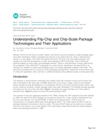
XFM-5050-UVProduct Datasheet - PreliminaryXFM-5050-UV2-chip Surface MountUVC LEDFeatures Ultra-high power UVC LED: 120 mW output power at 275 nmTable of ContentsBinning Structure. . . . . . . . . . 2 Compact, cost effective 5050 package Designed to maximize irradiance in high flow applications Wide viewing angle of 130 Ordering Information . . . . . . 3 Standard SMT ProcessOptical and ElectricalCharacteristics. . . . . . . . . . . . . 4 RoHS and REACH compliantMechanical Dimensions. . . . 7Soldering Profile. . . . . . . . . . . 8Product Shipping &Labeling Information . . . . . . 9ApplicationsPrecautions for Use. . . . . . . . 10History of Changes. . . . . . . . 11 Air Purification Water Purification Surface Disinfection Medical Device Sterilization Appliance Sterilization Food & Beverage Preparation1PDS-003111 Rev C 2020 Luminus Devices, Inc. - All Rights ReservedLuminus Devices, Inc. T 408.708.7000 www.luminus.com1145 Sonora Ct. Sunnyvale, CA 94086
XFM-5050-UVProduct Datasheet - PreliminaryXFM-5050-UV Binning StructureXFM-5050-UV LEDs are tested for radiometric flux and wavelength at a drive current of 500 mA, 20 ms single pulse at 250 C and placedinto one of the following radiometric flux (FF) and wavelength (WWW) bins. The LEDs can also be driven at other drive currents, toachieve the correlated flux values listed in the table.Radiometric Flux BinsMinimum Flux(mW)500 mA, 250 CMaximum Flux(mW)500 mA, 250 C350 mA650 mA800 B140160100184225Flux Bin (FF)Correlated Minimum Flux(mW) at 250 CNote 1:Product lifetime is a function of drive current. Sustained operation at absolute maximum current of 800 mA will result in a reduction of device lifetimecompared to typical forward drive currents (350 mA-500 mA). Actual device lifetimes will also depend on junction temperature. Contact Luminus forinformation on product lifetime.Note 2:Correlated minimum flux values are for reference only. XFM-5050s are tested and binned only at the test current of 500 mA.Wavelength BinsWavelength Bin (WWW)Minimum Wavelength (nm)Maximum Wavelength (nm)270270275275275280280280285Note 1: Luminus maintains a /- 6% tolerance on flux measurements and /- 1 nm on wavelength measurements.Note 2: Individual bins are not orderable. Please refer to product ordering information on page 3 for a list of ordering part numbers.2PDS-003111 Rev C 2020 Luminus Devices, Inc. - All Rights ReservedLuminus Devices, Inc. T 408.708.7000 www.luminus.com1145 Sonora Ct. Sunnyvale, CA 94086
XFM-5050-UVProduct Datasheet - PreliminaryPart Number NomenclatureXFMProduct FamilyXFM: UVC Surface MountPackage5050 UV Package Type5050: 5.0 mm x 5.0 mm B130 FFWWW-## ColorPackage ConfigurationBin kitUVB: 2-chip version130: 130 emission angleFlux (FF) andWavelength(WWW) binkit codeSee ordering informatonOrdering Part NumbersThe table below lists ordering part numbers available for XFM-5050-UV LEDs. The part number includes a bin kit, a group of flux andwavelength bins described in page 2, that are shippable for a given ordering part number. Individual flux or wavelength bins are notorderable . Flux bin listed is minimum bin shipped - higher bins may be included at Luminus’ discretion.Wavelength RangeWavelength Bins270-280Radiometric FluxOrdering Part NumberBin Kit Flux CodeMin. Flux (mW)270, 5050-UV-B130-DD280-01270-280270, M-5050-UV-B130-DE280-013PDS-003111 Rev C 2020 Luminus Devices, Inc. - All Rights ReservedLuminus Devices, Inc. T 408.708.7000 www.luminus.com1145 Sonora Ct. Sunnyvale, CA 94086
XFM-5050-UVProduct Datasheet - PreliminaryOptical and Electrical nimum Forward VoltageVf-min10.0VTypical Forward VoltageVf-typ13.5VMaximum Forward VoltageVf-max15.5VΔλ12nm2θ1/2130 Rth3.1 C/WSymbolValueUnitIf-max800mATj95 CTest CurrentFWHMViewing AngleThermal Resistance (junction-solder point)Absolute Maximum RatingsParameterForward CurrentJunction TemperatureNote 1:Ratings are based on operation at a constant junction temperature of Tj 25 ºC. Test conditions: 500 mA, 20 ms pulse at 25ºC.Note 2:XFM-5050-UV LEDs are designed for operation up to an absolute maximum forward drive current as specified above. Product lifetime data isspecified at typical forward drive currents. Sustained operation at absolute maximum currents will result in a reduction of device lifetime comparedto typical forward drive currents. Actual device lifetimes will also depend on junction temperature.Note 3:Caution must be taken not to stare at the radiation emitted from UV LEDs.4PDS-003111 Rev C 2020 Luminus Devices, Inc. - All Rights ReservedLuminus Devices, Inc. T 408.708.7000 www.luminus.com1145 Sonora Ct. Sunnyvale, CA 94086
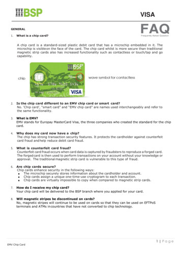
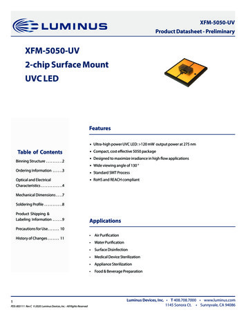
XFM-5050-UVProduct Datasheet - PreliminaryOptical & Electrical CharacteristicsRelative Power vs. Forward CurrentRelative Power vs. Junction TemperaturePeak Wavelength Shift vs. Forward CurrentPeak Wavelength Shift vs. Junction TemperatureForward Voltage vs. Forward CurrentForward Voltage Shift vs. Junction Temperatureφ/φ(500 mA) , 20 ms pulse, Tj 25 Cλp λp(If ) - λp (500 mA), 20 ms pulse, Tj 25 C25 C , 20 ms pulse5PDS-003111 Rev C 2020 Luminus Devices, Inc. - All Rights Reservedφ/φ(25 C) , 20 ms pulse, 500 mAλp λp(Tj) - λp (25 C), 20 ms pulse, If 500 mAΔVf Vf(Tj) - Vf(25 C), 20 ms pulse, If 500 mALuminus Devices, Inc. T 408.708.7000 www.luminus.com1145 Sonora Court, Sunnyvale, CA 94086 USA
XFM-5050-UVProduct Datasheet - PreliminaryTypical SpectrumRadiation Pattern- TBA6PDS-003111 Rev C 2020 Luminus Devices, Inc. - All Rights ReservedLuminus Devices, Inc. T 408.708.7000 www.luminus.com1145 Sonora Court, Sunnyvale, CA 94086 USA
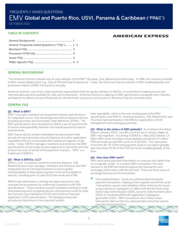
XFM-5050-UVProduct Datasheet - PreliminaryMechanical DimensionsRecommended Solder Pad & Stencil Pattern7PDS-003111 Rev C 2020 Luminus Devices, Inc. - All Rights ReservedLuminus Devices, Inc. T 408.708.7000 www.luminus.com1145 Sonora Ct. Sunnyvale, CA 94086
XFM-5050-UVProduct Datasheet - PreliminarySoldering ProfileProfile SettingPb-Free ProfileAverage Ramp-up Rate (Tsmax, Tp)1 C/secPreheat Temperature Min (Tsmin)100-150 CPreheat Temperature Max (Tsmax)180-200 CPreheat Time (tsmin to tsmax)60-120 secLiquidus Temperature (TL)217 CTime Maintained Above TL (tL)Peak / Classification Temperature (TP)50-80 sec260 CTime within 5 C of Actual Peak Temp (tP)Max 10 secRamp-Down Rate2-3 C /sec25 C to Peak Temperature time4 minsLuminus recommends that users follow the recommended soldering profile provided by the manufacturer of the solder paste used.Note that this general guideline may not apply to all PCB designs and configurations.8PDS-003111 Rev C 2020 Luminus Devices, Inc. - All Rights ReservedLuminus Devices, Inc. T 408.708.7000 www.luminus.com1145 Sonora Ct. Sunnyvale, CA 94086
XFM-5050-UVProduct Datasheet - PreliminaryProduct Shipping & Labeling Information- TBAAll XFM-5050 products are packaged and labeled with their respective bin as outlined in the tables on pages 2 & 3.XFM-5050-UV Label Information9PDS-003111 Rev C 2020 Luminus Devices, Inc. - All Rights ReservedLuminus Devices, Inc. T 408.708.7000 www.luminus.com1145 Sonora Ct. Sunnyvale, CA 94086
XFM-5050-UVProduct Datasheet - PreliminaryPrecautions for storage, handling and use of UV LEDs1. UV LightXFM-5050-UV LEDs are short wavelength, deep UV LEDs. During operation, the LED emits high intensity UVC radiation, which is harmful to skin and eyes. UV light is also hazardous to skin and may cause cancer. Avoid exposure to deep UV light when LED is operational.2. Static Electricity (ESD)While XFM-5050 LEDs have built-in Zener protection diodes, they are particularly sensitive to ESD (Electrostatic Discharge). Staticelectricity and surge voltages seriously damage UV LEDs and can result in complete failure of the device. Precautions must be takenagainst ESD when handling or operating these devices.3. Operating ConditionsIn order to ensure the correct functioning of these LEDs, compliance to maximum allowed specifications is important. UV LEDs are particularly sensitive to drive currents that exceed the max operating specifications and may be damaged by such drive curents. The useof current regulated drive circuits is strongly recommended when operating these devices. Customers should also provide adequatethermal management to ensure LEDs do not exceed maximum recommended temperatures. Operating LEDs at temperatures in excess of specification will result in damage and possibly complete failure of the device.10PDS-003111 Rev C 2020 Luminus Devices, Inc. - All Rights ReservedLuminus Devices, Inc. T 408.708.7000 www.luminus.com1145 Sonora Ct. Sunnyvale, CA 94086
XFM-5050-UVProduct Datasheet - PreliminaryHistory of ChangesRevDescription of ChangeA08/24/2020Initial ReleaseB09/27/2020Updated drawingsC11/2020Updated ordering part numbers and bin kits; updated Rth, typos fixed11PDS-003111 Rev C 2020 Luminus Devices, Inc. - All Rights ReservedLuminus Devices, Inc. T 408.708.7000 www.luminus.com1145 Sonora Ct. Sunnyvale, CA 94086
All XFM-5050 products are packaged and labeled with their respective bin as outlined in the tables on pages 2 & 3. Luminus Devices, Inc. T 408.708.7000 www.luminus.com 1145 Sonora Ct. Sunnyvale, CA 94086 XFM-5050-UV Product Datasheet - Preliminary 1. UV Light XFM-5050-UV LEDs are short wavelength, deep UV LEDs. .