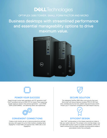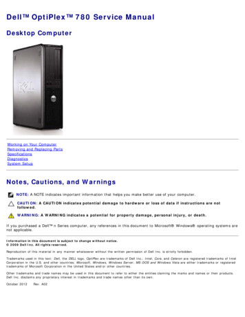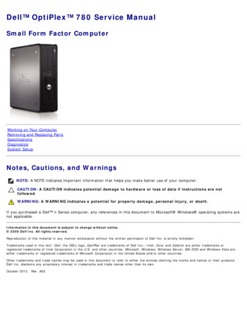
Transcription
OptiPlex 5050 Small Form FactorOwner's ManualRegulatory Model: D11SRegulatory Type: D11S002
Notes, cautions, and warningsNOTE: A NOTE indicates important information that helps you make better use of your product.CAUTION: A CAUTION indicates either potential damage to hardware or loss of data and tells you how to avoid the problem.WARNING: A WARNING indicates a potential for property damage, personal injury, or death. 2017 Dell Inc. or its subsidiaries. All rights reserved. Dell, EMC, and other trademarks are trademarks of Dell Inc. or its subsidiaries. Other trademarksmay be trademarks of their respective owners.2017 - 11Rev. A01
Contents1 Working on your computer. 6Safety instructions. 6Before working inside your computer.6Turning off your computer.7Turning off your computer — Windows 10. 7Turning off your computer — Windows 7.7After working inside your computer.72 Removing and installing components. 8Recommended tools. 8Back cover. 8Removing cover. 8Installing the cover. 9Expansion card. 9Removing expansion card. 9Installing the expansion card. 11Coin cell battery.11Removing coin cell battery. 11Installing the coin cell battery.12Front Bezel. 12Removing bezel.12Installing the bezel. 13Speaker. 13Removing speaker. 13Installing the speaker.14Intrusion switch.14Removing intrusion switch.14Installing the intrusion switch. 15Storage.15Removing 2.5-inch drive assembly.15Removing the 2.5-inch drive from the bracket. 17Installing the 2.5-inch drive into the bracket.18Installing the 2.5-inch drive assembly. 18Optical drive. 18Removing the optical drive.18Installing the optical drive. 20M.2 PCIe SSD . 20Removing the M.2 PCIe SSD . 20Installing the M.2 PCIe SSD . 21Heat sink assembly. 21Removing heat sink assembly. 21Installing the heat sink assembly. 22Processor. 22Contents3
Removing processor. 22Installing the processor.23Memory module. 24Removing memory module. 24Installing the memory module.24SD card reader.24Removing the SD card reader. 24Installing the SD card reader.25Power supply unit. 25Removing power supply unit (PSU). 25Installing the power supply unit (PSU).28Power switch.28Removing power switch.28Installing the power switch. 29System board. 30Removing system board.30Installing the system board. 33System board layout. 34System board jumper.343 M.2 Intel Optane Memory Module 16 GB. 36Overview.36Intel OptaneTM Memory Module Driver Requirements.36M.2 Intel Optane Memory Module 16 GB. 36Product specifications.39Environmental Conditions. 40Troubleshooting.414 Technology and components.42USB features. 42USB 3.0/USB 3.1 Gen 1 (SuperSpeed USB).42Speed.42Applications.43Compatibility. 44HDMI 1.4.44HDMI 1.4 Features.44Advantages of HDMI. 445 System setup.46Boot Sequence.46Navigation Keys.46System and setup password.47Assigning a system password and setup password. 47Deleting or changing an existing system and/or setup password. 48System Setup options. 48Updating the BIOS in Windows .54Enabling smart power on. 554Contents
6 Software.56Supported operating systems. 56Downloading drivers. 56Downloading the chipset driver. 56Intel chipset drivers.57Intel HD Graphics drivers. 577 Troubleshooting your computer. 59Diagnostic power LED codes. 59Power LED issue. 60Diagnostic error messages. 60System error messages.638 Technical specifications. 64Processor specifications. 64Memory specifications. 65Video specifications.65Audio specifications.65Communication specifications. 66Storage specifications. 66Ports and connectors specifications. 66Power supply specifications.67Physical dimension specifications. 67Controls and lights specifications.67Environmental specifications. 689 Contacting Dell. 69Contents5
1Working on your computerSafety instructionsUse the following safety guidelines to protect your computer from potential damage and to ensure your personal safety. Unless otherwisenoted, each procedure included in this document assumes that the following conditions exist: You have read the safety information that shipped with your computer. A component can be replaced or, if purchased separately, installed by performing the removal procedure in reverse order.WARNING: Disconnect all power sources before opening the computer cover or panels. After you finish working inside thecomputer, replace all covers, panels, and screws before connecting to the power source.WARNING: Before working inside your computer, read the safety information that shipped with your computer. For additionalsafety best practices information, see the Regulatory Compliance Homepage at www.Dell.com/regulatory complianceCAUTION: Many repairs may only be done by a certified service technician. You should only perform troubleshooting and simplerepairs as authorized in your product documentation, or as directed by the online or telephone service and support team.Damage due to servicing that is not authorized by Dell is not covered by your warranty. Read and follow the safety instructionsthat came with the product.CAUTION: To avoid electrostatic discharge, ground yourself by using a wrist grounding strap or by periodically touching anunpainted metal surface at the same time as touching a connector on the back of the computer.CAUTION: Handle components and cards with care. Do not touch the components or contacts on a card. Hold a card by itsedges or by its metal mounting bracket. Hold a component such as a processor by its edges, not by its pins.CAUTION: When you disconnect a cable, pull on its connector or on its pull-tab, not on the cable itself. Some cables haveconnectors with locking tabs; if you are disconnecting this type of cable, press in on the locking tabs before you disconnect thecable. As you pull connectors apart, keep them evenly aligned to avoid bending any connector pins. Also, before you connect acable, ensure that both connectors are correctly oriented and aligned.NOTE: The color of your computer and certain components may appear differently than shown in this document.Before working inside your computerTo avoid damaging your computer, perform the following steps before you begin working inside the computer.1Ensure that you follow the Safety instructions.2Ensure that your work surface is flat and clean to prevent the computer cover from being scratched.3Ensure you follow the Turning off your computer.4Disconnect all network cables from the computer.CAUTION: To disconnect a network cable, first unplug the cable from your computer and then unplug the cable from thenetwork device.5Disconnect your computer and all attached devices from their electrical outlets.6Press and hold the power button while the computer is unplugged to ground the system board.7Remove the cover.NOTE: To avoid electrostatic discharge, ground yourself by using a wrist grounding strap or by periodically touching anunpainted metal surface at the same time as touching a connector on the back of the computer.6Working on your computer
Turning off your computerTurning off your computer — Windows 10CAUTION: To avoid losing data, save and close all open files and exit all open programs before you turn off your computer.1Click or tap2Click or tap.and then click or tap Shut down.NOTE: Ensure that the computer and all attached devices are turned off. If your computer and attached devices did notautomatically turn off when you shut down your operating system, press and hold the power button for about 6 seconds toturn them off.Turning off your computer — Windows 7CAUTION: To avoid losing data, save and close all open files and exit all open programs before you turn off your computer.1Click Start.2Click Shut Down.NOTE: Ensure that the computer and all attached devices are turned off. If your computer and attached devices did notautomatically turn off when you shut down your operating system, press and hold the power button for about 6 seconds toturn them off.After working inside your computerAfter you complete any replacement procedure, ensure that you connect any external devices, cards, and cables before turning on yourcomputer.1Replace the cover.2Connect any telephone or network cables to your computer.CAUTION: To connect a network cable, first plug the cable into the network device and then plug it into thecomputer.3Connect your computer and all attached devices to their electrical outlets.4Turn on your computer.5If required, verify that the computer works correctly by running ePSA diagnostics.Working on your computer7
2Removing and installing componentsThis section provides detailed information on how to remove or install the components from your computer.Recommended toolsThe procedures in this document require the following tools: Small flat blade screwdriver Phillips # 1 screwdriver Small plastic scribeBack coverRemoving cover1Follow the procedure in Before working inside your computer.2To release the cover:a Slide the blue retention tab to the right to unlock the cover [1].b Slide the cover toward the back of the computer [2].8Removing and installing components
3Lift the cover to remove from the computer [3].Installing the cover1Place the cover on the computer and slide the cover until it clicks into place.2Follow the procedure in After working inside your computerExpansion cardRemoving expansion card1Follow the procedure in Before working inside your computer.2Remove the cover.3Pull the metal tab to open the expansion card latch.Removing and installing components9
4To remove the expansion card:ab10Pull the release tab at the base of the expansion card [1].Disconnect and lift the expansion card away from the connector [2].Removing and installing components
Installing the expansion card1Insert the expansion card into the connector on the system board.2Press the expansion card until it clicks into place.3Close the expansion card latch and press it until it clicks into place.4Install the cover.5Follow the procedure in After working inside your computer.Coin cell batteryRemoving coin cell battery1Follow the procedure in Before working inside your computer.2Remove the:a3coverTo remove the coin cell battery:abPress the release latch until the coin cell battery pops out [1].Remove the coin cell battery from the connector on the system board [2].Removing and installing components11
Installing the coin cell battery1Hold the coin cell battery with the " " sign facing up and slide it under the securing tabs at the positive side of the connector.2Press the battery into the connector until it locks into place.3Install the:4Follow the procedure in After working inside your computer.acoverFront BezelRemoving bezel1Follow the procedure in Before working inside your computer.2Remove the cover.3To remove the front bezel:ab12Lift the tabs to release the front bezel from the computer [1].Remove the front bezel from the computer [2].Removing and installing components
Installing the bezel1Insert the tabs on the bezel into the slots on the computer.2Press the bezel until the tabs clicks into place.3Install the cover.4Follow the procedure in After working inside your computerSpeakerRemoving speaker1Follow the procedure in Before working inside your computer.2Remove the:abcd3coverbezel2.5–inch drive assemblyoptical driveTo remove the speaker:abDisconnect the speaker cable from the system board [1].Press the release tabs and pull the speaker out from the computer [2] [3].Removing and installing components13
Installing the speaker1Insert the speaker into the slot and press it until it clicks into place.2Connect the speaker cable to the connector on the system board.3Install the:abcd4optical drive2.5–inch drive assemblybezelcoverFollow the procedure in After working inside your computer.Intrusion switchRemoving intrusion switch1Follow the procedure in Before working inside your computer.2Remove the:3To remove the intrusion switch:aab14coverDisconnect the intrusion switch cable from the connector on the system board [1][2].Slide the intrusion switch and lift it away from the computer [3].Removing and installing components
Installing the intrusion switch1Insert the intrusion switch into the slot on the chassis.2Connect the intrusion switch cable to the system board.3Install the:a4coverFollow the procedure in After working inside your computer.StorageDepending on the configuration you choose, you will find either one 3.5–inch hard drive assembly or two 2.5–inch hard drive assemblies.Removing 2.5-inch drive assembly1Follow the procedure in Before working inside your computer.2Remove the:3To remove the 2.5-inch drive assembly:aabcoverPush the release tabs and disconnect the 2.5-inch drive power cable [1][2].Disconnect the 2.5-inch drive assembly cables from the drives [3] [4].Removing and installing components15
4To remove the drive assembly:ab16Hold and push the release tab [1].Lift the 2.5-inch drive assembly from the computer [2].Removing and installing components
Removing the 2.5-inch drive from the bracket1Follow the procedure in Before Working Inside Your Computer.2Remove the:ab3cover2.5-inch drive assemblyTo remove the drive:abPull one side of the drive bracket to disengage the pins on the bracket from the slots on the drive [1].Lift the drive out of the 2.5-inch drive bracket [2].Removing and installing components17
Installing the 2.5-inch drive into the bracketNOTE: To install a secondary hard drive, the grommets will be shipped separately.1Align and insert the pins (secured by grommets) on the drive bracket with the slots on the sides of the drive.2Install the:ab32.5-inch drive assemblycoverFollow the procedure in After Working Inside Your Computer.Installing the 2.5-inch drive assembly1Insert the drive assembly into the slot on the computer.2Connect the power cable to the slot on the drive bracket.3Install the:4Follow the procedure in After working inside your computer.acoverOptical driveRemoving the optical drive1Follow the procedure in Before working inside your computer.2Remove the:abc3coverbezel2.5–inch drive assemblyTo release the optical drive module:ab18Unthread the cables through the retention clip [1].Slide the blue tab to unlock the optical drive module [2].Removing and installing components
4To remove the optical drive module:abc5Pull the tab upward to release the module [1].Holding the tab, disconnect the optical drive cables [2].Slide and lift the optical drive module away from the computer [3].To remove the optical drive:abSlide the tab to release the optical drive [1].Push the optical drive away from the module [2][3].Removing and installing components19
Installing the optical drive1Slide the optical drive
OptiPlex 5050 Small Form Factor Owner's Manual Regulatory Model: D11S Regulatory Type: D11S002. Notes, cautions, and warnings NOTE: A NOTE indicates important information that helps you make better use of your product. CAUTION: A CAUTION indicates either potential damage to hardware or loss of data and tells you how to avoid the problem.