Transcription
Radian Series Inverter/ChargerGS4048AGS8048AOperator’s Manual
About OutBack Power TechnologiesOutBack Power Technologies is a leader in advanced energy conversion technology. OutBack productsinclude true sine wave inverter/chargers, maximum power point tracking charge controllers, and systemcommunication components, as well as circuit breakers, batteries, accessories, and assembled systems.ApplicabilityThese instructions apply to OutBack inverter/charger models GS4048A and GS8048A only.Contact InformationAddress:Corporate Headquarters17825 – 59th Avenue N.E.Suite BArlington, WA 98223 USAWebsite:http://www.outbackpower.comEuropean OfficeHansastrasse 8D-91126Schwabach, GermanyDisclaimerUNLESS SPECIFICALLY AGREED TO IN WRITING, OUTBACK POWER TECHNOLOGIES:(a) MAKES NO WARRANTY AS TO THE ACCURACY, SUFFICIENCY OR SUITABILITY OF ANYTECHNICAL OR OTHER INFORMATION PROVIDED IN ITS MANUALS OR OTHERDOCUMENTATION.(b) ASSUMES NO RESPONSIBILITY OR LIABILITY FOR LOSS OR DAMAGE, WHETHER DIRECT,INDIRECT, CONSEQUENTIAL OR INCIDENTAL, WHICH MIGHT ARISE OUT OF THE USE OF SUCHINFORMATION. THE USE OF ANY SUCH INFORMATION WILL BE ENTIRELY AT THE USER’S RISK.OutBack Power Technologies cannot be responsible for system failure, damages, or injury resulting fromimproper installation of their products.Information included in this manual is subject to change without notice.Notice of CopyrightRadian Series Inverter/Charger Operator’s Manual 2017 by OutBack Power Technologies.All Rights Reserved.TrademarksOutBack Power, the OutBack Power logo, and Grid/Hybrid are trademarks owned and used by OutBackPower Technologies, Inc. The ALPHA logo and the phrase “member of the Alpha Group” are trademarksowned and used by Alpha Technologies Inc. These trademarks may be registered in the United Statesand other countries.Date and RevisionSeptember 2017, Revision BPart Number900-0161-01-01 Rev B
Table of ContentsIntroduction . 7Audience . 7Symbols Used . 7General Safety . 7Welcome to OutBack Power Technologies . 8Inverter Functions . 9GS8048A . 10GS4048A . 10Inverter Controls . 10MATE3-Class System Display and Controller . 10Operation . 11Inverter Functionality. 11Description of AC Input Modes . 11Generator . 12Support . 13Grid Tied . 14Grid Interface Protection Menu . 15UPS . 16Backup . 16Mini Grid . 16GridZero . 18Description of Inverter Operations . 21Inverting . 21DC and AC Voltages . 21AC Frequency . 22Search . 23Input . 24AC Current Settings . 24AC Source Acceptance . 25Generator Input . 26Transfer . 26Battery Charging. 27Charge Current . 27Charge Cycle . 28Advanced Battery Charging (ABC) . 29Charging Steps . 29New Charging Cycle . 31Equalization . 34Battery Temperature Compensation . 34Offset . 36Grid Support . 37Auxiliary Terminals . 39Metering . 43MATE3-Class System Display Screens . 43Inverter Screens . 43Battery Screen . 44900-0161-01-01 Rev B3
Table of ContentsTroubleshooting . 45Basic Troubleshooting . 45Module Select . 50Error Messages. 51Warning Messages . 52Temperature Events . 53Grid Tie Warnings .53Disconnect Messages . 54Sell Status . 55Specifications . 57Electrical Specifications . 57Mechanical Specifications . 58Environmental Specifications . 59Temperature Derating . 59Regulatory Specifications . 60Listings . 60Certifications . 60Compliance. 60Limiting Charge Current (Multiple Inverters) . 61Firmware Revision . 63Default Settings and Ranges . 63Definitions . 68Index . 694900-0161-01-01 Rev B
Table of ContentsList of TablesTable 1Table 2Table 3Table 4Table 5Table 6Table 7Table 8Table 9Table 10Table 11Table 12Table 13Table 14Table 15Table 16Table 17Table 18Summary of Input Modes . 19Charge Currents for Radian Models . 27Offset Interaction with AC Source . 36AUX Mode Functions . 42Troubleshooting. 45Error Troubleshooting . 51Warning Troubleshooting . 52Inverter Temps . 53Grid Tie Warnings . 53Disconnect Troubleshooting . 54Sell Status Messages . 55Electrical Specifications for Radian Models . 57Mechanical Specifications for Radian Models . 58Environmental Specifications for Radian Models . 59Chargers On and Current Settings . 62Charge Currents for Calculations . 62Radian Menu Items . 63Terms and Definitions . 68List of FiguresFigure 1Figure 2Figure 3Figure 4Figure 5Figure 6Figure 7Figure 8Figure 9Figure 10Figure 11Radian Series Inverter/Charger . 8Charging Stages Over Time . 28Charging Stages Over Time (24/7) . 28Repeated Charging (1st and 2nd Cycles) . 32Repeated Charging (3rd, 4th, and 5th Cycles) . 33Grid Support Function Screen . 38Home Screen . 43Inverter Screens . 43Battery Screen. 44AC Test Points . 45Temperature Derating . 59900-0161-01-01 Rev B5
Table of ContentsTHIS PAGE INTENTIONALLY LEFT BLANK.6900-0161-01-01 Rev B
IntroductionAudienceThis book provides instructions for the functional settings and operation of this product. Theseinstructions are for use by qualified personnel who meet all local and governmental coderequirements for licensing and training for the installation of electrical power systems with ACand DC voltage up to 600 volts. This product is only serviceable by qualified personnel. Do notuse this product without reading the Radian Series Inverter/Charger Installation Manual.Symbols UsedWARNING: Hazard to Human LifeThis type of notation indicates that the hazard could be harmful to human life.CAUTION: Hazard to EquipmentThis type of notation indicates that the hazard may cause damage to the equipment.IMPORTANT:This type of notation indicates that the information provided is important to the installation,operation and/or maintenance of the equipment. Failure to follow the recommendations insuch a notation could result in voiding the equipment warranty.NOTE:This type of notation indicates useful information. This symbol is not always used.MORE INFORMATIONWhen this symbol appears next to text, it means that more information is available in other manuals relating to thesubject. The most common reference is to the Radian Series Inverter/Charger Installation Manual. Anothercommon reference is the system display manual.General SafetyWARNING: Limitations on UseThis equipment is NOT intended for use with life support equipment or other medicalequipment or devices.WARNING: Reduced ProtectionIf this product is used in a manner not specified by GS product literature, the product’sinternal safety protection may be impaired.CAUTION: Equipment DamageOnly use components or accessories recommended or sold by OutBack Power Technologiesor its authorized agents.900-0161-01-01 Rev B7
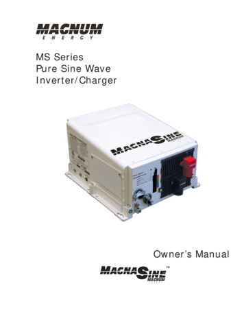
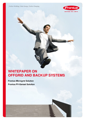
IntroductionWelcome to OutBack Power TechnologiesThank you for purchasing the OutBack Radian Series Inverter/Charger. It is designed to offer acomplete power conversion system between batteries and AC power.As part of an OutBack Grid/Hybrid system, it can provide off-grid power, grid backup power,or grid-interactive service which sells excess renewable energy back to the utility.Figure 18Radian Series Inverter/Charger900-0161-01-01 Rev B
IntroductionInverter Functions Battery-to-AC inverting which delivers power to run backup loads and other functions Provides split-phase output Adjustable range of output voltage Settable nominal output frequencyAC-to-battery charging (OutBack systems are battery-based) Accepts a wide variety of AC sources Requires split-phase inputUses battery energy stored from renewable resources Can utilize stored energy from many sources (PV arrays, wind turbines, etc.) OutBack FLEXmax charge controllers will optimize PV power production as part of aGrid/Hybrid system Dual AC inputs allow direct connection to utility grid and AC generator Rapid transfer between AC source and inverter output with minimal delay time Uses the MATE3 class of System Display and Controller products, or the AXS Port SunSpecModbus Interface (sold separately) for user interface as part of a Grid/Hybrid system MATE3s system display is required for grid support functionality (see below)Supports the OPTICS RE online tool1 for a cloud-based remote monitoring and control application Requires the MATE3 or the AXS Port Visit www.outbackpower.com to downloadUses the HUB10.3 Communications Manager for stacking as part of a Grid/Hybrid system Stackable in parallel configuration up to ten inverters Certified by ETL to UL 1741 SA, CSA C22.2, and IEC 62109-1 Grid support functionality according to the requirements of UL 1741 SA Field-upgradeable firmware (from www.outbackpower.com); requires MATE3 product or AXS Port The MATE3s system display must be used when upgrading the inverter to firmware revision001.006.063 or higher.Seven selectable input modes for different applications Generator Support Grid Tied UPS Backup Mini Grid GridZeroNOTE:This product has a settable AC output range. In this book, many references to the outputrefer to the entire range. However, some references are made to 120/240 Vac or 60 Hzoutput. These are intended as examples only.1Outback Power Technologies Intuitive Control System for Renewable Energy900-0161-01-01 Rev B9
IntroductionGS8048A 8,000 watts (8 kW) continuous power at 48 Vdc 16.97 kVA peak surge capacity Modular internal design allows low idle consumption, high efficiency at both high and lowpower operationGS4048A 4,000 watts (4 kW) continuous power at 48 Vdc 8.48 kVA peak surge capacityInverter ControlsThe Radian inverter has no external controls or display pre-installed. It can operate normallywithout an external control or interface. Basic modes and settings are pre-programmed at thefactory. (See page 63 for default settings.) However, certain products can monitor, operate, orprogram the Radian. These include OPTICS RE and the MATE3 class of system display.See the Radian Series Inverter/Charger Installation Manual for information on wiring a manualon/off switch.MATE3-Class System Display and ControllerThe MATE3 class of system display products (sold separately) includes the MATE3 and theMATE3s. These are designed to accommodate programming and monitoring of a Grid/Hybridpower system. The system display provides the means to adjust the factory default settings tocorrectly match the installation where needed. It provides the means to monitor systemperformance and troubleshoot fault or shutdown conditions. It also has data logging andinterface functions using the Internet.Once settings are modified using a MATE3-class device, it can be removed from the installation.The settings are stored in the nonvolatile memory of the Radian inverter. However, it is highlyrecommended to include a system display as part of the system. This provides the means tomonitor system performance and respond quickly should it be necessary to correct a fault orshutdown condition.In a MATE3-class device, the Profile Wizard is a guided program for rapidly configuring devices.It prevents the need for repetitive programming when multiple common devices are used. Aftercollecting user input, it can automatically configure inverters to a series of preset values.Affected fields include system type, battery charging, and AC source configuration.IMPORTANT:10 The Radian inverter is only compatible with the MATE3 class of system display products.Radian revision 001.005.004 or lower can be used with any revision of MATE3s but can onlybe used with MATE3 revision 002.017.000 or higher. This product is not intended for use withthe OutBack MATE or MATE2 products. A MATE3s system display with revision 001.001.000 or higher must be used when operatingan FXR inverter with firmware revision 001.006.063 or higher. The Radian inverter can use the OPTICS RE online tool as a system display. OPTICS REmust be used in conjunction with a MATE3-class system display or with the AXS PortSunSpec Modbus Interface. Some functions are not based in the inverter, but are part of the system display’s firmware.They will not function if the system display is removed.900-0161-01-01 Rev B
OperationInverter FunctionalityThe Radian inverter can be used for many applications. Some of the inverter’s operations occurautomatically. Others are conditional or must be enabled manually before they will operate.Most of the inverter’s individual operations and functions can be programmed using the systemdisplay. This allows customization or fine tuning of the inverter’s performance.The Radian inverter has two sets of input connections, which are labeled GRID and GEN. Twodifferent AC sources can be connected during inverter installation.Before operating the inverter:The operator needs to define the application and decide which functions will be needed.The Radian inverter is programmed with seven AC input modes. Each mode is optimized for aparticular application. Some modes contain functions unique to that mode.The modes are described in detail following this section. To help decide which mode will beused, the basic points of each mode are compared in Table 1 on page 19.Apart from the input modes, Radian inverters possess a set of common functions or operations.These operations are described in detail beginning on page 20. Most of these items operate thesame regardless of which input mode is selected. The exceptions are noted where appropriate.NOTE:The Radian’s battery charger uses the same programming and settable limits regardless ofwhich input is used. It does not have independent charger settings on each input.Each distinct mode, function, or operation is accompanied by a symbol representing the inverterand that operation:These items represent the input from the ACDCsource, the output to the AC loads, DC functionsTRANSFER(inverting, charging, etc.), and the transfer relay.ACACINOUTArrows on each symbol represent power flow.The symbols may have other features depending on the operation.Description of AC Input ModesThese modes control aspects of how the inverter interacts with AC input sources. Each mode isintended to optimize the inverter for a particular application. The names of the modes areGenerator, Support, Grid Tied, UPS, Backup, Mini Grid, and GridZero. The modes aresummarized and compared in Table 1. See page 19.Both of the Radian’s inputs, GRID and GEN, can be programmed for separate modes. The GRID input can be set in the Grid AC Input Mode and Limits menu. The GEN input can be set in the Gen AC Input Mode and Limits menu.900-0161-01-01 Rev B11
OperationNOTE: The input terminals are labeled for grid and generator due to common conventions, notbecause of inverter requirements. Each input can accept any AC source as long as itmeets the requirements of the Radian inverter and the selected input mode. Ifnecessary, the GEN terminals can accept grid power. The opposite is also true. However, if using the Gen Alert or AGS functions, the generator must use the GENterminals. See page 39 for details on Gen Alert and the system display literature fordetails on AGS.When multiple inverters are stacked together in parallel, the master inverter’s input mode isimposed on all slaves. (See the stacking section in the Installation Manual.) The slave settingsare not changed; they retain any mode that was previously programmed. However, the slavewill ignore its programmed mode and use that of the master. This also applies to anyparameters in the mode menu (Voltage Limit, Connect Delay, and so on).The following pages compare the various features of each input mode.GeneratorThe Generator mode allows the use of a wide range of AC sources, including generators with arough or imperfect AC waveform. In other modes, a “noisy” or irregular waveform may not beaccepted by the inverter. (Self-excited induction generators may require this mode when usedwith the Radian.) Generator allows these waveforms to be accepted. The charging algorithmof this mode is designed to work well with AC generators regardless of power quality orregulation mechanism. The generator must still comply with the inverter’s nominal inputspecifications. (See page 25.)BENEFITS: This mode enables the battery charging function to tolerate a wider range of generator performanceand waveform irregularities than other modes. See page 26 for recommended parameters for sizinga generator. Generator mode can also be used to accommodate grid variability or irregularities. The inverter willnot export power to the grid in this mode. A programmable delay timer is available which will allow a generator to stabilize before connection.In MATE3-class system displays, this menu item is Connect Delay. It is available in both the GridAC Input Mode and Limits and the Gen AC Input Mode and Limits menus, depending on whichinput is being programmed.NOTES: Any AC fluctuations that are accepted by the inverter will be transferred to the output. The loadswill be exposed to these fluctuations. It may not be advisable to install sensitive loads underthese conditions. The name of Generator mode does not mean that the inverter requires a generator input whenusing this mode. The use of this mode does not require the use of the GEN input terminals; eitherinput can be used. Conversely, the inverter is not required to be placed in this mode just because agenerator is installed.12900-0161-01-01 Rev B
OperationSupportThe Support mode is intended for systems that use the utility grid or a generator. In somecases the amount of current available from the source is limited due to size, wiring, or otherreasons. If large loads are required, the Radian inverter augments (supports) the AC source.The inverter uses battery power and additional sources to ensure that the loads receive thepower they demand.In a MATE3-class system display, the Grid Input AC Limit dictates the maximum AC draw forthe Grid input. The Gen Input AC Limit sets the maximum draw for the Gen input. TheSupport function takes effect if the AC demand on either input exceeds the AC Limit setting.BENEFITS: Large inverter loads can be powered while staying connected to the AC input, even if the input islimited. The added battery power prevents overload of the input source, but the batteries are not inconstant use. The Radian inverter will offset the loads with excess renewable energy if it is available from thebatteries. See page 36 for more information on the Offset function.NOTES:IMPORTANT:The inverter will draw energy from the batteries when the loads exceed the appropriateAC Limit. With sustained loads and no other DC source, the batteries may discharge to theLow Battery Cut-Out point. The inverter will shut down with a Low Battery error. (Seepages 21 and 51.) To prevent the loss of power, load use should be planned accordingly.IMPORTANT:A “noisy” or irregular AC source may prevent Support from working normally. The inverterwill transfer the power, but will not support the source, charge the batteries, or interact withthe current in any other way. This problem is more common with generators smaller thanthe wattage of the inverter. Because the inverter limits the current draw from the AC source, it will reduce the charge rate asnecessary to support the loads. If the loads equal the appropriate AC Limit setting, the charge ratewill be zero. If the AC loads exceed the AC Limit setting, the Support function is activated. Instead of charging,the inverter will take power from the batteries and use it to support the incoming AC current. The Support function is not available in any other input mode.900-0161-01-01 Rev B13
OperationGrid TiedIMPORTANT:Selling power to the utility company requires the authorization of the local electric jurisdiction.How the utility company accommodates this will depend on their policies on the issue. Somemay pay for power sold; others may
an FXR inverter with firmware revision 001.006.063 or higher. The Radian inverter can use the OPTICS RE online tool as a system display. OPTICS RE must be used in conjunction with a MATE3-class system display or with the AXS Port SunSpec Modbus Interface.

![Welcome [s3-ap-southeast-2.amazonaws ]](/img/28/wmi5140-user-manual.jpg)