Transcription
WHITEPAPER ONOFFGRID AND BACKUP SYSTEMSFronius Microgrid SolutionFronius PV-Genset Solution
Fronius International GmbHVersion1.0/2014Solar EnergyFronius reserves all rights, in particular rights of reproduction, distribution and translation.No part of this work may be reproduced in any way without the written consent of Fronius. It must not be saved, edited, reproduced ordistributed using any electrical or electronic system.You are hereby reminded that the information published in this document, despite exercising the greatest of care in its preparation, issubject to change and that neither the author nor Fronius can accept any legal liability.Gender-specific wording refers equally to female and male form.Whitepaper on Offgrid and Backup Systems2/17
TABLE OF CONTENTS1Introduction .42Inverter-Charger driven microgrids .52.1AC-coupling .62.1.1Basic Inverter-Charger AC-coupling .72.1.2AC-coupling as grid back-up.72.1.3Optimising Microgids / Extended Inverter-Charger AC-coupling .72.2Fronius Microgrid Solution .83Operation of PV-Genset Systems .103.1Fronius PV-Genset Solution .123.1.1Protecting and optimizing the diesel genset .133.1.2Optimising the PV-Genset system .133.1.3Online system monitoring .143.1.4Products for the Fronius PV-Genset Solution .144Appendix: Inverter features supporting microgrids .154.1Gradual Frequency dependent Power Reduction (GFdPR) .154.2Gradual Voltage dependent Power Reduction (GVdPR).164.3Reactive Power as a function of Voltage (Volt-VAr-curve) .16.Whitepaper on Offgrid and Backup Systems3/17
1INTRODUCTIONPhotovoltaics (PV) are continually gaining the focus of microgrid (MG) operators. In the fast growing sector ofMGs, PV and wind power are currently providing the best and cost effective solutions, in comparison totraditional fossil fuel resources like diesel, oil, coal, etc. Annual costs of PV systems have been decreasing,and when compared to the increasing costs of traditional fossil fuels and their transportation aspects, thevery positive market for solar business becomes subtle.A MG is an energy system comprising of distributed generators, consumers and storage facilities. Thesedistributed generators can not only be fuelled by fossil energy resources (diesel, gas, etc.), but also byrenewables (biogas, PV, fuel cells, etc.). MGs can be established in areas with weak security of energysupply and in remote rural communities or industrial areas. Generally, MGs are able to work in parallel to anexisting power grid (“on-grid-mode”), in addition to the islanding mode (“off-grid-mode”). The main focus ofthis document lies on the “off-grid” behavior, in case of such MGs. Diesel generator sets in MGs are able tobuild a stable grid (voltage, frequency) within limited areas offering a unique advantage that the site of powergeneration is located in the vicinity of loads. MGs act like little self-sustaining cells where the demand andgeneration are in equilibrium. The lack of long distance distribution networks makes the energy supplythrough these grids even more valuable, since the distribution losses become minimal.We classified the MGs into two types:/ Inverter-Charger driving small and medium scale MGs (up to 300 kVA) with or without a backup ACsource (diesel genset or AC backup grid)Fronius Microgrid Solution/ Diesel Genset driven medium and large scale MGs (100 kVA up to MVA)Fronius PV-Genset SolutionMGs formed by Inverter/Chargers are usually smaller than dieselgrids1 ( 300kVA), and are used to powercommercial buildings or smaller settlements in remote locations.“Dieselgrids” are rather large, and are located in areas, where it is economically or technically difficult to buildthe transmission lines. They are popular in countries with variations in its geographical demography(resulting in a number of remote locations, for e.g. Australia), and in countries with a weak security of energysupply, for e.g. regions of India and the Asia/Pacific, in general. The size of such MGs can be of several100s kVA.1MGs mainly powered by diesel gensets.Whitepaper on Offgrid and Backup Systems4/17
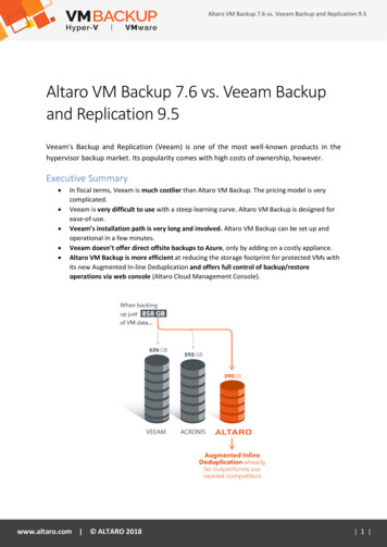
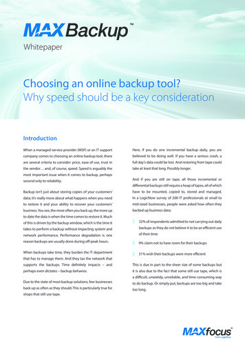
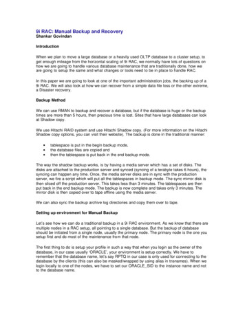
2INVERTER-CHARRGER DDRIVENN MICROOGRIDSSInverter-Chaarger driven MGs usuallyy consist of tthree main coomponents. The Inverterr-Charger itself, a batteryybank to stoore/provide thetelectricitty required, and an external powerr source (baack-up AC-grid, back-uppdiesel, reneewables) to faacilitate the recharging oof batteries.It is importaant to know thhat the Inverrter-Charger is in charge of keeping the system inn balance (i.ee. active anddreactive powwer), in addiition to perfoorming all en ergy management relateed tasks (forr e.g. UPS2, turn-on/turn-offs, back-uup diesel setss, etc.).Since the Inverter-Charger must beb able to mmeet the demmands of the load, its nnominal powwer must beeeak load. It i s usually possible for thee Inverter-Chharger to suustain supplyydimensioned above the expected peof extra powwer (exceedding the nammeplate’s rat ing) for shorrt durations (i.e., up to sseveral secoonds), whichhmight be esssential in caase of inrushh currents or to trip the protectionpdevvices – in caase of issuess addressinggthe safety aaspects.Sizing the bbattery is impportant, sincee they are thee main and pricepdriving factor of succh systems.The maximuum achievabble system-siize largely deepends on user’suchoice of type of Innverter-Chargger. Usually,,several unitts per phasee can be connected in pparallel (two up to ten) dependingdoon the manufacturer anddtype. Thereefore, the maaximum 3 phhase system size is limiteed, for e.g. 636 kVA or upp to 300 kVAA. For singleephase systeems 21 kVA / 100 kVA is also a possiibility.The integraation of reneewables like PV into succh systems cancbe achieeved either by employinng MaximummPower Poinnt Tracking (MPPT) charrge controllerrs on the 122 . 48 Vbusb which iss typically called as “DC--coupling”, oor through thee use of conventional griid-tied inverters that feedds-in on the AAC Bus, which is termeddas “AC-couppling”.Figure 1: TypicalTsystem toopology of a DCC-coupled microogrid system2UPS referss to Uninterrruptable Powwer Supply. . .a Backup SystemsWhitepaperr on Offgrid and75/17
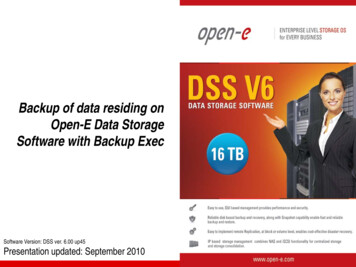
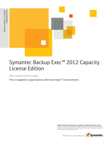
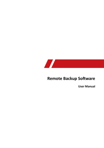
nverter-Charrger acts as a voltage sourcesthat delivers thee exact real--time energyyOn the AC side, the Inon (apparentt power). Deepending onn what systeem topologyy the user pprefers to chhoose, solarrconsumptioarge the battteries using MPPT charge controlleers to ensurere that the batteriesbcannenergy can directly chaharge duringg the availabbility of sun irradiation. This is a coonventional aapproach thaat has beennalways rechfollowed by energy harvvesters for seeveral years . The disadvvantage of DC-coupling iss that the ovverall systemmnd that the loow voltage leevel leads too very high currents on thhe DC side – resulting innefficiency iss very low, anthe requiremment of expeensive electrical componeents.2.1ACC-couplinggA more up-tto-date apprroach of integrating renewentional grid-wables like PV into MG systems is tto use convetie inverterss feeding-in directlydto thee AC-side. TThis is possibble because of the technoological leapp in continualldevelopmennt of inverterrs over the laast years. Tooday’s PV innverters and Inverter-Chaargers are muchmsmarterrthan those – from a couple of yearsyago. Features likke frequency sweep too protect baatteries frommng on the Invverter-Charger side, and the active anda reactive power charaacteristic currves to keeppovercharginthe grid in bbalance on thhe grid-tie invverters have led this to a possibility.Such a systtem topologyy is termed asa “AC-couplled”. The effficiency in suuch a case off coupling is significantlyyhigher, becaause the powwer produced from PV caan be directlly fed to the loads througgh the highlyy efficient PVVinverters. Innverter-Charrger serves to just bridgge and link the gap. AnyAexcess oof solar eneergy can beeadditionally stored in thee battery bannk.Figure 2: Typical schemmatic of an AC-ccoupled microgriid system. . .a Backup SystemsWhitepaperr on Offgrid and76/17
The main advantages of AC coupling include the following:/ High system efficiency because of efficient components and less conversion losses in case direct powersupply to the loads/ Economical cost of components/ Possibility of easy up-gradation of existing systems2.1.1 Basic Inverter-Charger AC-couplingIn remote regions that are deprived of access to electrical energy, battery inverters offer a simple solution tobuild MGs.Battery inverters when replaced by Inverter-Charger – renders other sources of energy tointeract within the system. Additionally, diesel gensets can be used as a back-up option – in case of battery’sState of Charge SoC) drops, because of the lack of solar irradiation./ The basic rule valid for every Inverter-Charger driven MG application mentions that an installed PVpower (i.e. max. AC Power) must not exceed the installed Inverter-Charger power.This ensures that the Inverter-Charger is not overloaded at any time.A strategy to increase the PVpenetration in such systems is described in 2.1.3./ All Inverter-Charger units in parallel or three phase systems must be connected to the same battery2.1.2 AC-coupling as grid back-upIt is not necessary to connect the entire electrical installation to the Inverter-Charger while employing it as anAC-back-up. For such a case, it should be sufficient to define some critical loads that are required in anevent of outage. In such cases, the installed capacity of Inverter-Charger can even be lower than that of astand-alone case. Nevertheless, if the grid-tie inverter should also be on-line in a back-up case, it can beinstalled on the AC-out terminals of the Inverter-Charger.2.1.3 Optimising microgrids / Extended Inverter-Charger AC-couplingAs a matter of fact, batteries are the known and obvious cost drivers in an Inverter-Charger MG. Toguarantee an un-interrupted supply of power, it becomes essential to have sufficient back-up of powercapacity, and therefore, battery banks must not be undersized. By adding a quantum of intelligence into thesystem – it is possible to oversize the AC-coupled PV inverters with respect to the installed Inverter-Chargercapacity (by monitoring the power fed into the battery). Therefore it needs a control that measures the loadand controls PV power in a way that the maximum allowed power of charging the batteries trough theInverter-Charger is not exceeded at any time.If most power demand is during the day-time (certain base load) it renders feasibility to cover most of thedemand, supplied by PV (to reduce the battery charging losses), and also to ensure simultaneous chargingof the batteries. This could lead to the decrease of the battery bank sizing, and in turn results the system tobe cost effective. In case of reduced solar irradiation the Inverter-Charger nevertheless must be able tocover the peak load or small backup generators help out during these rare events. Also in case of poorirradiation that last for several days, a backup generator can prevent form the system from “run dry”.Whitepaper on Offgrid and Backup Systems7/17
2.2Froonius Micrrogrid SollutionThe Froniuss Microgrid SolutionSofferrs an AC-couupled systemm with the following listed advantages:/ High syystem efficiency through the use of eefficient systeem componeents and redduced converrsion losses,,in casee of direct suppply to the looads/ Econommical cost of componentss/ Possibiility of easy up-gradationuof existing ssystemsThe Fronius inverter providespas much PV eenergy as possiblepto the Microgridd. Automaticc PV powerrreduction iss necessary in times where the load iss lower than the possiblee PV producttion and the batteries areefull (or whenn the charginng power of thet Inverter-CCharger is tooo small).Typically thee power of thhe inverter iss controlled wwithout any communicatcion. In this caase the frequency drooppof the Invertter-Charger anda the frequuency droopp of the Fronius inverter causecoptimaal power setppoints.ency droop, a function ffor voltage dependentdpoower reductiion to prevent from overrIn addition to the frequewer control functions,fcan be activateed and fully configured.cvoltage caused tripping,, and several reactive powbility to implement load measuremeent to limit the maximuum power thhat is to beeThere is allso a possibconsumed bby the Invertter-Charger. This can bee realised witth using the Fronius PV--System Conntroller. Withh. . .a Backup SystemsWhitepaperr on Offgrid and78/17
V-system cann be large in comparison to the size oof the Inverter-charger forrthese possibilities the size of the PVoptimized syystems.It is also possible to conntrol the Fronnius inverter via a 3rd partty device. Thhe available ccommunication solutionssotocol) and/or Fronius Inteerface Protoocol.are Modbuss RTU or TCP (SunSpec Alliance ProFurthermoree, the protecction settingss in the Microe settings forrogrid Setup are configurrable. Whethher the samethe Microgrid are also applicableaforr systems whmetimes connnected to thee utility grid, depends onnhich are somlocal connection rules.Scan be realized with all Fronius Inverterrs the Froniuus PV-System ControllerrThe Froniuss Microgrid Solutionand Currentt Transducerrs.with FroniusInverter-Chaarger produccts tested in combinationcs inverters:/ Studer Xtendernd Quattro/ Victron MultiPlus anhe Fronius MicrogridMSeetup can be used withouut further coonfiguration effort at theeWith these products thssetttings work inssystemms (The Inveerter-Chargeer has to been correctly sizedFronius invverter. The standardaccording itss manuals).configured a. . .a Backup SystemsWhitepaperr on Offgrid and79/17
3OPPERATIION OF PV-GENSET SYSTEMSMSnsets and photovoltaicptechnology can be coombined in perfect harrmony. Althhough theseeDiesel gentechnologiees have rareely been in demand by the same users in thee past, bringging the twoo generationnogether hass now beccome extremd especiallyysystems tomely benefficial technically, ecoloogically andeconomically.areas or regions where thhe electricityy supply is patchy or extremely expeensive, grids powered byyIn remote adiesel genssets are an absoluteamusst. The cost per kilowatt hour of electricity from a diesel gensset is largelyye, dependingg as it does on fuel and other variable costs. OnlyOa small proportion is fixed. Theechangeablecosts can vaary widely deepending on country, tra nsport distannce and increeasing oil coosts on the global markett( 0.05 – 2.55 per kWh).The price trrend in the photovoltaicpsectorsis mucch more possitive. Over thhe past few yyears the coosts per kWhhfrom PV sysstems have droppedddrammatically aroound the globbe ( 0.07 - 0.14 per kWh)).For this reaason there is a clear finanncial justificaation for integgrating a Froonius PV-Ge nset solutionn into almosttevery diesel-powered syystem. Everyy unused dieesel kWh savves money.pecially in caase of MGss, the balancce of powerr is mandatoory for safee and stableeFor any grrid, and espoperation. In large interr-connected grids, surpluus spinning reserverand control mecchanisms aree considereddalance (primaary, secondaary, and tertiaary control).to keep the system in ba. . .a Backup SystemsWhitepaperr on Offgrid and710/17
In a MG system, conditions are mostly similar to the ones that are as mentioned above. A stable operation ofa MG is of high significance. PV inverters are intended to not negatively impact the operation of gensetsystems. Power quality and reliability are therefore intended to improve, and if not, are at least intended toremain at the same level.Various control algorithms that can be supported by PV inverters are further explained in this paper.Gensets can be operated in isochronous or droop mode. Isochronous case of operation refers to theoperation of generator at one constant frequency (similar to the inter-connected grids). Droop modeoperation refers to the variation of frequency with respect to the load (i.e. open circuit frequency is higherthan frequency at full load).Firstly, active and reactive power generation and demand are required to be in balance. A mismatch in activepower mainly leads to frequency deviation, and a mismatch in reactive power to a voltage deviation. In case,when two or more synchronous generators feed one load - the load sharing is typically implemented viaeither a droop load sharing or an isochronous load sharing.Droop load sharing refers to the alteration of frequency with respect to the load such that the actual loadremains supplied by all generators in the system, approximately at the same level.Isochronous load sharing requires communication between gensets - either by means of an analog signal ordigital communication (CAN, RS485 or Ethernet).Using grid-tie inverters without special functionality3 in MGs is - provided that the island detection is disabled– not a big issue, as long as inverter’s power is very low ( 10%) compared to the generator power and theload. In this case, the inverter’s power is always consumed by the loads and that the actual grid source isslightly unburdened.Increasing the installed PV power closer to the generator’s power poises challenging aspects in terms ofcontrol. If PV power installed lies between 10 and 30% of generator’s nominal power, an external device forcontrolling the inverter’s output can be necessary. For increased PV power capacity (above 30 %) ofgenerator’s nominal power, an external control is necessary and also relevant information of consumptionbecomes essential. Otherwise the synchronous generator could get into operation modes that aredisadvantageous for permanent operation or even dangerous in case of reverse power.To participate in MGs with diesel gensets and significant PV penetration, it is important to control theinverter’s output reliable and fast by means of a superior control device.3”Normal“ grid-tie inverter with unity power factor (PF 1) and no additional characteristic curves.Whitepaper on Offgrid and Backup Systems11/17
3.1Froonius PV-GGenset SoolutionIf the power from the photovoltaic systemsis prooportionally quite large, the entire syystem must be optimallyyo obtain the best possiblee diesel savi ngs.controlled toThis is wheere the Froniius PV-Systeem Controlleer comes intoo play. By using data froom the Fronius invertersstogether with load meaasurements (as well as diesel gensset measureements weree necessary), the entireeed. This allowws the Froniius inverters to be controolled. If seveeral diesel geensets are innsystem can be monitorehese too havve to be conntrolled at th e same timee. Further pootential for ooptimisation existsewhereeuse, then thcontrollable (in terms of time) loads can also be taken into acccount. . .a Backup SystemsWhitepaperr on Offgrid and712/17
3.1.1otecting andd optimizing the diesel ggensetProThe diesel ggenset is a fundamentalfpart of the ssystem. Proteecting it has to take the hhighest priority, as losinggthe generator would cauuse the entiree power suppply to fail.The Froniuss PV-Systemm Controller assumesathe following funnctions:/ Ensurinng that the minimummnummber of dieseel gensets neeeded is in usse during anyy given situaation./ Checking that the dieseldgensetts are alwayss being usedd in a manner that has thee lowest posssible impacttn at low loads.on servvice life, even/ Guaranntees an exxtremely quick and res ponsive conntrol over thhe PV outpput. As a reesult, powerrfluctuattions are commpensated immmediately aand the strainn on the diessel genset is reduced draamatically.3.1.2e PV-Gensett systemOpttimising theIt is very eeasy for a smmall PV sysstem in relattion to the looad to pay for itself finaancially, butt it does nottrepresent a cost-effectivve form of opptimisation. AAs the PV output never has to be resstricted, the savings canndentified fromm the annual energy calcursimply be idulated in the respective region.The differennce between the costs off producing PPV energy annd the costs of producingg electricity frrom diesel issnormally quuite large. Thhe saving is thereforetmuuch higher if the size of thhe PV systemm has been designed soothat temporrary power restrictionsrarea the normm. This signifficantly increases the ammount of powwer supplieddfrom photovvoltaics. In order to identify the most cost-effectivve PV systemm size for eacch project, it is importantt. . .a Backup SystemsWhitepaperr on Offgrid and713/17
to examine the insolation and load profile alongside the variable diesel power costs and the cost of the PVsystem.Simulations are then used to calculate the highest possible savings that could be achieved.Fronius can provide you with an unbeatable support in the planning of your PV-Genset system.3.1.3Online system monitoringEvery PV-Genset system can be designed, monitored, analysed and visualised at any time using the freeFronius Solar.web online portal. Up-to-date system data can be accessed at any time and is clearlypresented: the portal is very user-friendly and easy to use, and a comprehensive range of analysis functionsis included.Fronius Solar.web is also available as an app to allow you to check your PV system data from yoursmartphone at your own convenience.3.1.4Products for the Fronius PV-Genset SolutionAll Fronius inverters can be used in a PV-Genset system. The Fronius PV-System Controller assumes allcontrol functions over the system. Depending on the configuration, the required measuring accessories willalso be offered.Due to the open nature of Fronius communication solutions, it is also possible to implement individualsolutions containing third-party components. With the Fronius Datamanager 2.0 or Fronius DatamanagerBox 2.0, it is possible to incorporate all components into a control system using Modbus RTU or TCP withthe SunSpec Inverter Control Model.Whitepaper on Offgrid and Backup Systems14/17
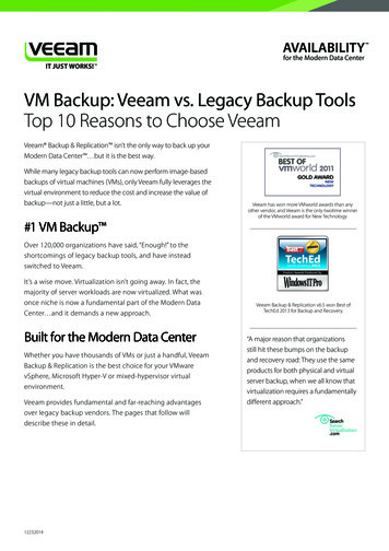
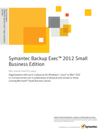
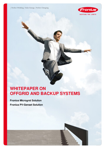
4APPPENDIIX: INVEERTER FEATURES SUUPPORTTINGMIICROGRRIDSRegardless of the useer’s intentionn of designi ng an AC-ccoupled Inveerter-Charge r MG, or a PV-Gensettonius PV-inveerters come with a multii-featured funnctionality coompared to thet inverterssapplication, modern Frow only neccessary to feeed-in with unityupower factorf(PF 1), but the capability offof the past. Earlier, it waslatest FRONNIUS PV inveerters extendds far beyondd that.Key featurees to portrayy can includde: Gradual Frequency dependent Power Reduuction (GFdPR), P(f) orrreactive powwer characteeristics, viz., cosPhi(P), QQ(V) or Q(P) (also knownn as Frequenncy-Watt-curvve, Watt-PF-curve, Volt-VVAr-curve, Watt-VAr-curWrve.)A control function, for e.g. P(V) (powwer limitationn as a functioon of voltagee; Volt-Watt-ccurve) prevents inverterssg due to oveervoltage, andd therefore, aalso plays ann important rolerin MG appplications.from trippingGrid-tie inveerters with reactiverpowwer functionaality, P(f) annd P(V) can be easily cconfigured too be able tooparticipate in MGs with positive influences.4.1Graadual Freqquency deependent Power Reeduction (GGFdPR)The most immportant conntrol strategyy in MGs is tto be able too reduce the feed-in powwer according to the griddfrequency. As most Invverter-Charger manufactturers use frrequency swweep to proteect batteriess from beinggd, GFdPR presentspa keykfeature tto prevent the system fromfbecomiing unstablee. Therefore,,overchargedFronius inveerters use a special P(f) function to rreduce their power to zeero, if the Invverter-Charger increasessthe value off frequency.For e.g. at frequency vaalue of 51 HzH inverter sttarts to reduce the poweer, and at 522.9 Hz the poower feed isso. The inverteer further discconnects at a frequency value of 53 Hz.Halmost zeroDiesel genssets react on load stepss by alterati on of frequeency until a new equilibbrium is attaained (1-5 s,,depending on the load steps). A situation of PPV power suupply to the full load andd excess feeds into theemust be stricttly avoided. GFdPR alsoo has a positive effect aftter load rejecction, due to its speed offgenerator mreaction ( 440ms).epecting GFFdPR strateggy to ensuree secure eneergy supplyyFigure 3: Schematic de. . .a Backup SystemsWhitepaperr on Offgrid and715/17
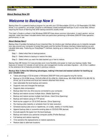
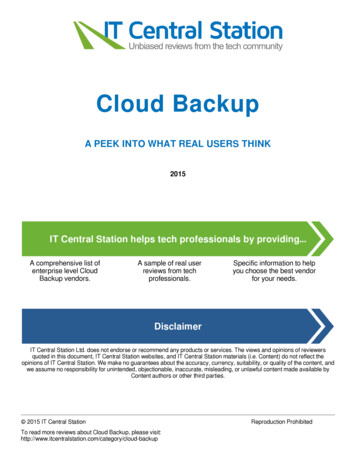
To top thinngs off – inndividual paarameters likke bend freequency or reduction ggradient aree completelyyconfigurablee, by means of a display to be able tto meet the widewrange ofo requiremennts of a MG, which needdto be defineed by the MGG operator.4.2Graadual Volttage dependent Powwer Reducction (GVddPR)Another straategy to stabbilize power quality and security of energyesupply is throughh GVdPR. If the value offvoltage excceeds a definned threshold limit, poweer from the inverter reduuces. This ccompensatess the voltageerise causedd by the inveerter and theereby restrictts the voltagge to exceedd the threshoold limit thatt causes theedisconnectioon of inverteers.The parameeter set for GVdPRGcomprises of volltage threshoold from wheere on the GGVdPR is acctive, a staticcgradient (in %Pn/V) and two dynammic gradientss (in %Pn/s)) – one for attenuationaaand the otheer for return.amic gradientts are importtant parametters for voltagge dips and swells.These dynaFigure 4: SchematicSdeepicting GVVdPR strateggy to ensuree secure eneergy supplyy4.3Reactive Powwer as a functionfof Voltage (Volt-VAr--curve)Imbalance iin reactive power also haas an influennce on poweer quality in MGs.MSynchrronous geneerators whichhact over-exited lead to rise of voltagge at the terrminals, and those that acta under-exxited lower thhe voltage attt reactive powerpin balaus-inverters alsoause a chharacteristic curve that issthe terminals. To keep theance, Froniugurable – through the usse of four seet-points, if reequired. Thee Q(V) charaacteristic is characterizeddeasily configby an area around the nominal voltage, where reactive power is zero (called as “ddeadband”). Outside theewer follows a gradient to a certain reaactive power limit. If this limit is attainned, reactiveedeadband, reactive powains constantt until the tripp limits of invverter.power rema.
stand-alone case. Nevertheless, if the grid-tie inverter should also be on-line in a back-up case, it can be installed on the AC-out terminals of the Inverter-Charger. 2.1.3 Optimising microgrids / Extended Inverter-Charger AC-coupling As a matter of fact, batteries are the known and obvious cost drivers in an Inverter-Charger MG. To