Transcription
Virtual Library ExtensionConfiguring the MVS Host Software for VLEVersion 1.0E14094-02Revision 02Submit comments about this document to STP FEEDBACK US@ORACLE.COM.
Configuring the MVS Host Software for VLEE14094-02Oracle welcomes your comments and suggestions for improving this book. Contact us at STP FEEDBACK US@ORACLE.COM. Please include the title, part number, issue date, and revision.Copyright 2010, 2011 Oracle and/or its affiliates. All rights reserved.This software and related documentation are provided under a license agreement containing restrictions on use and disclosure and are protected by intellectualproperty laws. Except as expressly permitted in your license agreement or allowed by law, you may not use, copy, reproduce, translate, broadcast, modify,license, transmit, distribute, exhibit, perform, publish, or display any part, in any form, or by any means. Reverse engineering, disassembly, or decompilationof this software, unless required by law for interoperability, is prohibited.The information contained herein is subject to change without notice and is not warranted to be error-free. If you find any errors, please report them to us inwriting.If this is software or related software documentation that is delivered to the U.S. Government or anyone licensing it on behalf of the U.S. Government, thefollowing notice is applicable:U.S. GOVERNMENT RIGHTS Programs, software, databases, and related documentation and technical data delivered to U.S. Government customers are"commercial computer software" or "commercial technical data" pursuant to the applicable Federal Acquisition Regulation and agency-specific supplementalregulations. As such, the use, duplication, disclosure, modification, and adaptation shall be subject to the restrictions and license terms set forth in theapplicable Government contract, and, to the extent applicable by the terms of the Government contract, the additional rights set forth in FAR 52.227-19,Commercial Computer Software License (December 2007). Oracle USA, Inc., 500 Oracle Parkway, Redwood City, CA 94065.This software or hardware is developed for general use in a variety of information management applications. It is not developed or intended for use in anyinherently dangerous applications, including applications which may create a risk of personal injury. If you use this software or hardware in dangerousapplications, then you shall be responsible to take all appropriate fail-safe, backup, redundancy, and other measures to ensure the safe use. Oracle Corporationand its affiliates disclaim any liability for any damages caused by use of this software or hardware in dangerous applications.Oracle is a registered trademark of Oracle Corporation and/or its affiliates. Oracle and Java are registered trademarks of Oracle and/or its affiliates. Othernames may be trademarks of their respective owners.AMD, Opteron, the AMD logo, and the AMD Opteron logo are trademarks or registered trademarks of Advanced Micro Devices. Intel and Intel Xeon aretrademarks or registered trademarks of Intel Corporation. All SPARC trademarks are used under license and are trademarks or registered trademarks ofSPARC International, Inc. UNIX is a registered trademark licensed through X/Open Company, Ltd.This software or hardware and documentation may provide access to or information on content, products, and services from third parties. Oracle Corporationand its affiliates are not responsible for and expressly disclaim all warranties of any kind with respect to third-party content, products, and services. OracleCorporation and its affiliates will not be responsible for any loss, costs, or damages incurred due to your access to or use of third-party content, products, orservices.2 Configuring the MVS Host Software for VLE
Table of ContentsPreface . 7Audience . 71What is Virtual Library Extension? . 9The VLE Appliance in a VSM System . 10VLE Appliance Hardware and Software . 112Configuring the MVS Host Software . 15Key Configuration Values . 16Subsystem Name . 16VLE Data Port and VSM5 IFF3 Card Target IP Addresses . 16IP Addresses of VLE Ports for Host (UUI) Communication . 16VMVC Volsers . 16VMVC Reclamation Threshold . 16MVS Host Software Configuration Tasks . 17Updating the SMC OMVS RACF Security Entry . 17Modifying the SMC SCMDS file . 18Updating the VTCS CONFIG Deck to Define VLE . 19Defining the VLE VMVCs to the MVS Host Software and Including VMVCs in an MVC Pool . 20Creating VMVC Volume Pools (6.2) . 20Updating the MVS Host Software Policies . 213Using the Concurrent Disaster Recovery Test Software with VLE . 23Overview . 23How to Use CDRT . 25CDRT Restrictions . 26Restrictions that The CDRT Software Enforces . 26Optimizing Access to Test and Production Resources . 27Running a DR Test . 28To run a DR test: . 28Cleaning Up After a DR Test . 34To remove DR test data from the VTSS buffer: . 34To resume normal operations: . 36Operational Scenarios . 36Scenario 1: Production and Test Sites, ACS and VLE at Each Site . 37Additional Operations for Scenario 1: . 40Revision 023
Scenario 2: Production and Test Sites, VLE Only at Each Site . 41Additional Operations for Scenario 2: . 44Scenario 3: Clustered VTSSs with Production and DR Test Sites . 45Preparing Your VTSS Cluster for a DR Test . 464Command Reference . 49ACTMVCGN - 7.0 and Above . 50Syntax . 50Parameters . 51Additional JCL Requirements . 51COMMtest - 6.2 and Above . 52Syntax . 52Parameters . 53CONFIG RECLAIM - 6.2 and Above . 55Syntax . 55Parameters . 55CONFIG RTD - 6.2 and Above . 57Syntax . 57Parameters . 58CONFIG STORMNGR - 7.0 and Above. 61Syntax - 7.0 and 7.1 . 61Parameters . 61CONFIG TAPEPLEX - 6.2 and Above. 62Syntax - 7.0 and 7.1 . 62Syntax - 6.2 . 62Parameters . 63DRTEST . 64Syntax . 64Parameters . 65Usage . 67JCL Requirements . 68Route - 6.2 and Above . 71Syntax . 71Parameters . 72SERVer - 6.2 and Above . 73Syntax . 73Parameters . 74STORclas Control Statement - 6.2 and Above . 78Syntax . 78Parameters . 79STORMNGR - 6.2 and Above . 81Syntax . 81Parameters . 82DISPLAY Command and Report Outputs . 83Display CONFIG Output . 83Display MIGrate DEtail Output . 84Display MVCPool Output . 85MVCRPT/MVCPLRPT/DISPLAY MVC Output . 87New/Updated Messages . 894 Configuring the MVS Host Software for VLE
HSC/VTCS Messages . 89SMC Messages . 91Revision 025
6 Configuring the MVS Host Software for VLE
PrefaceAudienceThis guide is for StorageTek or customer personnel who are responsible for configuring the MVShost software for Oracle’s StorageTek Virtual Library Extension (VLE).Revision 02Preface 7
Audience8 Configuring the MVS Host Software for VLE
1What is Virtual Library Extension?Oracle’s StorageTek Virtual Library Extension (VLE) is back-end disk storage for VTSS.VLE provides: An additional storage tier in the VSM solution. VTVs can now migrate from VTSS toVLE to provide fast access to recent data. Additionally, VTVs can transition from VLEstorage to tape media (MVCs) for long term archive.You can control how VTVs aremigrated and archived via the existing VTCS Management and Storage Classes,providing full backward compatibility with previous configurations. Back-end disk storage shared between multiple VTSS systems ensuring highavailability access to data.To VTCS, a VLE looks like a tape library except that the VTVs are stored in Virtual MultiVolume Cartridges (VMVCs) on disk. With VLE, you can configure either a VLE and tape ora VLE only (for example, with Tapeless VSM configurations) back-end VTV storagesolution. A VTSS can migrate VTVs to and recall them from a VLE, just as is done with areal tape library.Caution – Note that stopping SMC stops VTCS from sending messages to the VLE, whicheffectively stops data transfer. Therefore, you should ensure that VTCS activity isquiesced or VTCS is terminated before stopping SMC. You cannot use AT-TLS with the SMC HTTP server if you are using VLE. Note that in Tapeless VSM configurations, if you have only one VLE applianceattached to a specific VTSS and that VLE appliance goes offline, you lose access toany VTVs migrated to the VLE that are not resident in the VTSS until the VLEappliance comes back online.The VLE solution consists of:Revision 02 Virtual Tape Storage Subsystem (VTSS) hardware and microcode (VSM5s with IFF3cards). Virtual Tape Control Subsystem (VTCS) software and Storage Management Component(SMC). VLE hardware and software.What is Virtual Library Extension? 9
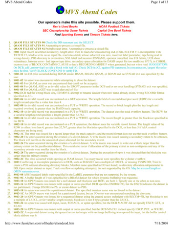
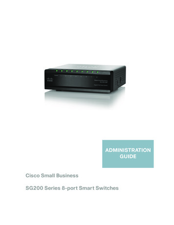
The VLE Appliance in a VSM SystemFIGURE 1-1 shows a VLE appliance connected to a VSM system.FIGURE 1-1 VLE Appliance in a VSM SystemAs FIGURE 1-1 shows: Multiple TCP/IP connections (between the VTSS’s IFF3 card IP ports and the VLE’s IPports) are supported as follows: A single VLE can connect up to 8 VTSSs, so VTSSs can share VLEs. A single VTSS can connect to up to 4 VLEs to increase buffer space for heavyworkloads.A single VTSS can be attached to: Only RTDs Only other VTSSs (clustered) Only VLEs Any combination of the above.TCP/IP is the only supported protocol for connections between the VLE appliance and theVTSS and for connections between the VLE appliance and MVS hosts running SMC andVTCS.10 Configuring the MVS Host Software for VLE
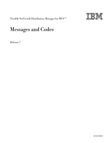
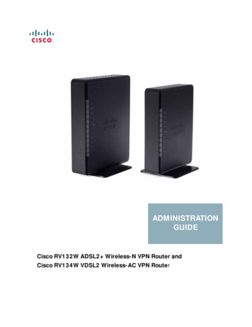
VLE Appliance Hardware and SoftwareThe VLE appliance, which is a factory-assembled unit in a Sun Rack II Model 1242, consistsof the following hardware: A server built on a 4470 platform. Four 1GigE ports for a combination of SMC UUI connections and service connections. A service (ILOM) port. Four Quad-port 1GigE cards, which provide 16 ethernet ports for data transfer. J4410 JBODs in a ZFS RAID array, available in effective capacities of 220TB, 440TB,660TB, or 880TB (assuming a 4 to 1 compression ratio when the data is migrated to theVLE). Two dual-port 10GigE NIC cards per server, which are required for the internal networkconnections for VLEs with 3 or more nodes.The VLE appliance software consists of: Solaris Operating System. ZFS file system and MySQL database. The VLE application software.FIGURE 1-2 shows the VLE subsystem architecture.FIGURE 1-2 VLE Subsystem ArchitectureRevision 02What is Virtual Library Extension? 11
As FIGURE 1-2 on page 12 shows, the VLE application software is comprised of: HTTP/XML is the data protocol for MVS host to VLE communications. The Universal User Interface (UUI) Request Handler, which processes UUI requests fromand produces responses to Storage Management Component (SMC) and Virtual TapeControl Software (VTCS). The UUI Request Handler determines which VLE componentsare used to service a request.UUI Request Handler calls: The PathGroup Manager to schedule VTV migrates and recalls. The PathGroupManager manages all Path Groups, where each Path Group manages a single VTV datatransfer between the VTSS and the VLE appliance. The Storage Manager to schedule all report generation. The VLE Storage Manager component manages the VMVC/VTV data and meta data onthe VLE appliance. The VLE Storage Manager stores VTV data on and retrieves it fromthe ZFS on the JBOD array. TCP/IP/IFF is the data protocol for MVS host to VLE communications, where the IP/IFF/ECAM component handles communications between the VTSS and the VLE appliance.12 Configuring the MVS Host Software for VLE
Revision 02What is Virtual Library Extension? 13
14 Configuring the MVS Host Software for VLE
2Configuring the MVS Host SoftwareThis chapter provides the MVS host software configuration for VLE as described in thefollowing sections:Revision 02 “Key Configuration Values” on page 16 “MVS Host Software Configuration Tasks” on page 17Configuring the MVS Host Software 15
Key Configuration ValuesThe following sections describes values required for software configuration that must matchvalues that are typically already set in the hardware configuration and recorded in the IP and VMVC Configuration.xls worksheet.Subsystem NameThe subsystem name of the VLE appliance (or entire grid, for a multi-node configuration),which is set by the VLE GUI, is specified in the following: Either the VTCS CONFIG TAPEPLEX STORMNGR parameter or the CONFIGSTORMNGR NAME parameter. The VTCS CONFIG RTD STORMNGR parameter. The SMC STORMNGR NAME parameter. The SMC SERVER STORMNGR parameter. The HSC STORCLAS STORMNGR parameter.VLE Data Port and VSM5 IFF3 Card Target IP AddressesThese IP addresses are initially set on the VSM5 DOP IFF IP Configuration Statuspanel and at the VLE GUI and the values must match. On the DOP panel, they are set as IPaddresses with their equivalent c:ip addresses shown, which are required for the CONFIGRTD IPIF parameter.IP Addresses of VLE Ports for Host (UUI) CommunicationThese addresses are required for the SMC SERVER IP parameter.VMVC VolsersRequired to define VMVCs to SMC/VTCS, method of definition depends on the softwareversion, see “Defining the VLE VMVCs to the MVS Host Software and Including VMVCs inan MVC Pool” on page 20.VMVC Reclamation ThresholdFor more information, see“VMVC Reclamation Threshold” on page 16.16 Configuring the MVS Host Software for VLE
MVS Host Software Configuration TasksAdding VLE to a VSM system requires the tasks described in the following sections: “Updating the SMC OMVS RACF Security Entry” on page 17 “Modifying the SMC SCMDS file” on page 18 “Updating the VTCS CONFIG Deck to Define VLE” on page 19 “Defining the VLE VMVCs to the MVS Host Software and Including VMVCs in anMVC Pool” on page 20 “Updating the MVS Host Software Policies” on page 21Updating the SMC OMVS RACF Security EntryThe VLE requires SMC to have an OMVS RACF security entry in order to have a TCP/IPconnection to the host.OMVS is a segment associated with the RACF userid. The SMC started task must have auserid associated with OMVS, either in the RACF STARTED class definition or theICHRIN03 LNKLST module. The userid associated with the SMC task needs to have anOMVS segment defined to it within RACF as follows:ADDUSER mber))Or, if the userid already exists but does not have an OMVS segment:ALTUSERRevision 02userid OMVS(UID(uidnumber))Configuring the MVS Host Software 17
Modifying the SMC SCMDS fileSMC manages all communication between VTCS and VLE, so SMC must know how toconnect to the VLE server. You do so by adding an SMC STORMNGR statement for each VLEsystem plus one or more SMC SERVER statements that define the TCP/IP control paths forthe VLE. For 7.0 and above, you may want to do this in your SMC CMDS file as shown inCODE EXAMPLE 2-1.TAPEPLEX NAME(TMVSA)LOCSUB(SLS0)SERVER NAME(ALTSERV) TAPEPLEX(TMVSA) HOSTNAME(MVSX) PORT(8888)STORMNGR NAME(VLE1)SERVER NAME(VLESERV1) STORMNGR(VLE1)IP(192.168.1.10)PORT(60000)CODE EXAMPLE 2-1 SMC Commands for VLECODE EXAMPLE 2-1 contains: A TAPEPLEX statement, which defines a single TapePlex, TMVSA, with an HSC/VTCS running on the same MVS host (SLS0). A SERVER statement, which defines a backup HSC/VTCS subsystem (ALTSERV)running on another host. A STORMNGR command that defines a VLE appliance (VLE1). A second SERVER command that defines a UUI communication path to the VLEappliance, where: The server name is VLESERV1. The STORMNGR parameter value is VLE1. The IP parameter value is the VLE port IP address of 192.168.1.10 for UUIcommunications. The PORT parameter value is 60000; this value is always used for the SERVERPORT parameter for SMC communication with a VLE appliance.18 Configuring the MVS Host Software for VLE
Updating the VTCS CONFIG Deck to Define VLEYou must update VTCS CONFIG deck to define the VLE and the connectivity from the VTSSsystems to the VLE. VLE 1.0 provides a single method of defining the VLE system to VTCS,which is via a CONFIG TAPEPLEX statement. This CONFIG TAPEPLEX statement definesthe TapePlex that VTCS is running under and provides the list of defined VLEs on theSTORMNGR parameter as shown in CODE EXAMPLE 2-2.TAPEPLEX THISPLEX TMVSA STORMNGR VLE1VTSS NAME VTSS1 LOW 70 HIGH 80 MAXMIG 8 MINMIG 4 RETAIN 5RTDNAME VL1RTD1 STORMNGR VLE1 IPIF 0A:0RTDNAME VL1RTD2 STORMNGR VLE1 IPIF 0A:1RTDNAME VL1RTD3 STORMNGR VLE1 IPIF 0I:0RTDNAME VL1RTD4 STORMNGR VLE1 IPIF 0I:1RTDNAME VL1RTD5 STORMNGR VLE1 IPIF 1A:0RTDNAME VL1RTD6 STORMNGR VLE1 IPIF 1A:1RTDNAME VL1RTD7 STORMNGR VLE1 IPIF 1I:0RTDNAME VL1RTD8 STORMNGR VLE1 IPIF 1I:1VTD LOW 6900 HIGH 69FFCODE EXAMPLE 2-2 CONFIG ExampleIn CODE EXAMPLE 2-2, note: The CONFIG TAPEPLEX statement, which defines TMVSA as the TapePlex that VTCSis running under and the connection to VLE1. The CONFIG RTD statements for VTSS1, which specify: The connections to VLE1. The IPIF value and an RTD name for each IFF target to VLE port connection.Specifying the Reclamation Policy for VMVCSVLE MVC media (VMVCs) is subject to fragmentation and must be reclaimed justlike real MVCs. The VMVC reclaim process, however, uses far fewer resources thana standard reclaim. The reclaim threshold for a VMVC is specified via the CONFIGRECLAIM VLTHRES parameter. The lower that you set VLTHRES, the more frequentVTCS will run reclaim on the VMVCs and the greater the effective capacity of theVMVS (less fragmentation).Revision 02Configuring the MVS Host Software 19
Defining the VLE VMVCs to the MVS Host Software andIncluding VMVCs in an MVC PoolVMVC volsers must be defined both to the MVS host software and to the VLE. The VMVCsare defined to the VLE as part of the VLE appliance configuration. The following sections tellhow to define the VMVCs to the MVS host software. Creating VMVC Volume Pools (7.0 and Above)1. Code HSC POOLPARM/VOLPARM statements to define the VMVC pools.For example, to define two separate pools for VLE1 and VLE2:POOLPARM NAME(LEPOOL1)TYPE(MVC) VOLPARM VOLSER(VL0000-VL880)POOLPARM NAME(LEPOOL2)TYPE(MVC) VOLPARM VOLSER(VL2000-VL2880)2. Run SET VOLPARM to validate the POOLPARM/VOLPARM statements.SET VOLPARM APPLY(NO)APPLY(NO) validates the statements without loading them. If you like the results, go toStep 3. Otherwise, rework your volume definitions, rerun this step, and if the definitionsare valid, then go to Step 3.3. Run SET VOLPARM to load the POOLPARM/VOLPARM statements.SET VOLPARM APPLY(YES) Creating VMVC Volume Pools (6.2)1. Code HSC VOLATTR statements to define the VMVCs to HSC.For example, to define two separate VMVC volser ranges for VLE1 and VLE2:VOLATTR SERIAL(VL0000-VL880) VOLATTR SERIAL(VL2000-VL2880)2. In your VTCS CONFIG JCL, code MVCVOL statements to define the VMVCs toVTCS.For example:MVCVOL LOW VL0000 HIGH VL880 MVCVOL LOW VL2000 HIGH VL28803. Code HSC MVCPOOL statements to define the VMVC pools.For example:MVCPOOL VOLSER(VL0000-VL880) MVCPOOL VOLSER(VL2000-VL2880)4. Run the VT MVCDEF and VOLDEF commands to activate the updated data set, forexample:.VT MVCDEF DSN(VSM.VMVCPOOL VOLDEF DSN(HSC.VOLATTR)20 Configuring the MVS Host Software for VLE
Updating the MVS Host Software PoliciesThe following sections tell how to update the MVS host software policies to direct data to theVLE system.Creating Storage and Management Classes for VLEManagement Classes specify how VTCS manages VTVs. The HSC MGMTclas controlstatement defines a Management Class and its attributes. For example, the DELSCR parameterof the MGMTclas statement specifies whether VTCS deletes scratched VTVs from the VTSS.Management Classes can also point to Storage Classes, which specify where migrated VTVsreside. The HSC STORclas control statement defines a Storage Class and its attributes.You specify the VLE system as the destination for migrated VTVs via the STORCLASSTORMNGR keyword. For example:STOR NAME(VLOCAL) STORMNGR(VLESERV1) STOR NAME(VREMOTE) STORMNGR(VLESERV2)The preceding statements define a “local” Storage Class (VLOCAL) on the VLSERV1 nodeor grid and a “remote” Storage Class (VREMOTE) on the on the VLSERV2 node or grid. Asthese STORCLAS statements specify, all migrations to storage class VLOCLAL or VREMOTE must go to the specified VLEs. You can be less restrictive than this if desired. Forexample, if you define an MVCPOOL that contains both VMVCs and MVCs you can setup the migration policies to migrate to a VLE but if the VLE becomes full or not available, to continue to migrate to real tape media (MVCs). For example the MVC pool DR isdefined as follows:POOLPARM NAME(DR)TYPE(MVC) VOLPARM VOLSER(VL0000-VL0100) VOLPARM VOLSER(ACS000-ACS099)Pool DR, therefore, contains both MVCs and VMVCs. A Storage Class that specifiespool DR will migrate first to VMVCs and only use MVCs if VMVCs are not available.For example:STOR NAME(DRCLASS) MVCPOOL(DR)This method is valuable if you have a configuration where both an ACS and a VLE areconnected to the VTSS systems.Next, to specify migration to VLE, you specify the VLE Storage Classes you defined viathe MGMTCLAS MIGPOL parameter. For example:MGMT NAME(M1) MIGPOL(VLOCAL,VREMOTE) MGMT NAME(M2) MIGPOL(DRCLASS)Management Class M1 migrates one VTV copy to the “remote” VLE, one copy to the“local” VLE. Management Class M2 migrates a single VTV copy to the Storage Classthat points to the “mixed” MVC pool that contains both MVCs and VMVCs.Revision 02Configuring the MVS Host Software 21
Note – In addition to directing migration to a VLE also consider:1. You can use the ARCHAge and ARCHPol parameters of the MGMTclas statement to set anArchive Policy for VTVs in a Management Class. When the VTV’s age exceeds theARCHAge value, the VTV is eligible for archive per the Storage Class(es) specified on theARCHPol parameter. You can use Archive Policies to archive (move) VTVs from VMVCsto MVCs as the VTVs age. For more information, see Managing HSC and VTCS.2. You can use STORSEL statements to cause VTCS to preference re
10 Configuring the MVS Host Software for VLE The VLE Appliance in a VSM System FIGURE 1-1 shows a VLE appliance connected to a VSM system. FIGURE 1-1 VLE Appliance in a VSM System As FIGURE 1-1 shows: Multiple TCP/IP connections (between the VTSS's IFF3 card IP ports and the VLE's IP