Transcription
Virtual Library ExtensionConfiguring the MVS Host Software for VLEVersion 1.3Revision 04Part Number: E39445-04Submit comments about this document to STP FEEDBACK US@ORACLE.COM.
Configuring the MVS Host Software for VLEE39445-04Copyright 2013 Oracle and/or its affiliates. All rights reserved.This software and related documentation are provided under a license agreement containing restrictions on use and disclosure and areprotected by intellectual property laws. Except as expressly permitted in your license agreement or allowed by law, you may not use, copy,reproduce, translate, broadcast, modify, license, transmit, distribute, exhibit, perform, publish, or display any part, in any form, or by anymeans. Reverse engineering, disassembly, or decompilation of this software, unless required by law for interoperability, is prohibited.The information contained herein is subject to change without notice and is not warranted to be error-free. If you find any errors, please reportthem to us in writing.If this is software or related software documentation that is delivered to the U.S. Government or anyone licensing it on behalf of the U.S.Government, the following notice is applicable:U.S. GOVERNMENT RIGHTS Programs, software, databases, and related documentation and technical data delivered to U.S. Governmentcustomers are "commercial computer software" or "commercial technical data" pursuant to the applicable Federal Acquisition Regulation andagency-specific supplemental regulations. As such, the use, duplication, disclosure, modification, and adaptation shall be subject to therestrictions and license terms set forth in the applicable Government contract, and, to the extent applicable by the terms of the Governmentcontract, the additional rights set forth in FAR 52.227-19, Commercial Computer Software License (December 2007). Oracle USA, Inc., 500Oracle Parkway, Redwood City, CA 94065.This software or hardware is developed for general use in a variety of information management applications. It is not developed or intended foruse in any inherently dangerous applications, including applications which may create a risk of personal injury. If you use this software orhardware in dangerous applications, then you shall be responsible to take all appropriate fail-safe, backup, redundancy, and other measures toensure the safe use. Oracle Corporation and its affiliates disclaim any liability for any damages caused by use of this software or hardware indangerous applications.Oracle is a registered trademark of Oracle Corporation and/or its affiliates. Oracle and Java are registered trademarks of Oracle and/or itsaffiliates. Other names may be trademarks of their respective owners.AMD, Opteron, the AMD logo, and the AMD Opteron logo are trademarks or registered trademarks of Advanced Micro Devices. Intel and IntelXeon are trademarks or registered trademarks of Intel Corporation. All SPARC trademarks are used under license and are trademarks orregistered trademarks of SPARC International, Inc. UNIX is a registered trademark licensed through X/Open Company, Ltd.This software or hardware and documentation may provide access to or information on content, products, and services from third parties.Oracle Corporation and its affiliates are not responsible for and expressly disclaim all warranties of any kind with respect to third-party content,products, and services. Oracle Corporation and its affiliates will not be responsible for any loss, costs, or damages incurred due to your access toor use of third-party content, products, or services.2 Configuring the MVS Host Software for VLE
Table of ContentsPreface . 5Audience . 51What is Virtual Library Extension? . 7Single Node VLE Configuration . 9Multi-Node VLE Systems. 10VLE to VLE Data Transfer. 11VTV Encryption . 11VTV Deduplication . 11Early Time To First Byte (ETTFB) . 12Frame Size Control . 12What’s New With VLE 1.3? . 13VLE Hardware and Software . 142Configuring the MVS Host Software . 17Key Configuration Values . 18Subsystem Name . 18VTSS Ethernet Port Addresses . 18IP Addresses of VLE Ports for Host (UUI) Communication . 18VMVC Volsers . 18VMVC Reclamation Threshold . 18VTV Deduplication . 19Early Time to First Byte (ETTFB) . 19MVS Host Software Configuration Tasks . 20Acquire the ELS supporting PTFs for VLE 1.3 . 20Updating the SMC OMVS RACF Security Entry . 20Modifying the SMC SCMDS file . 21Updating the VTCS CONFIG Deck to Define VLE . 22Defining the VLE VMVCs to the MVS Host Software and Including VMVCs in an MVC Pool .25Updating the MVS Host Software Policies . 263
4 Configuring the MVS Host Software for VLE
PrefaceAudienceThis guide is for StorageTek or customer personnel who are responsible for configuringtheMVS host software for Oracle’s StorageTek Virtual Library Extension (VLE).Preface 5
Audience6 Configuring the MVS Host Software for VLE
1What is Virtual Library Extension?Oracle’s StorageTek Virtual Library Extension (VLE) is back-end disk storage forVTSS. VLE provides: An additional storage tier in the VSM solution. VTVs can now migrate fromVTSS to VLE to provide fast access to recent data. Additionally, VTVs cantransition from VLE storage to tape media (MVCs) for long term archive.Youcan control how VTVs are migrated and archived via the existing HSCManagement and Storage Classes, providing full backward compatibility withprevious configurations. Back-end disk storage shared between multiple VTSS systems ensuring highavailability access to data.Note – For VLE 1.1 and above, a “VLE” is a collection of nodesinterconnected with a private network.To VTCS, a VLE looks like a tape library except that the VTVs are stored in VirtualMulti-Volume Cartridges (VMVCs) on disk. With VLE, you can configure either aVLE and tape or a VLE only (for example, with Tapeless VSM configurations) backend VTV storage solution. A VTSS can migrate VTVs to and recall them from a VLE,just as is done with a real tape library.Caution – Note that if you have a VLE system, HSC/VTCS uses SMC communicationservices to communicate with the VLE. To ensure that these services areavailable during VTCS startup, Oracle recommends that you first issue thestart command for HSC, then immediately issue the start command forSMC, while HSC is initializing. Also note that stopping SMC stops VTCS from sending messages to theVLE, which effectively stops data transfer. Therefore, you should ensurethat VTCS activity is quiesced or VTCS is terminated before stopping SMC. You cannot use AT-TLS with the SMC HTTP server if you are using VLE. Note that in Tapeless VSM configurations, if you have only a single-nodeVLE attached to a specific VTSS and that VLE goes offline, you lose accessto any VTVs migrated to the VLE that are not resident in the VTSS until theVLE comes back online.What is Virtual Library Extension? 7
The VLE solution consists of: Virtual Tape Storage Subsystem (VTSS) hardware and microcode. Virtual Tape Control Subsystem (VTCS) software and Storage ManagementComponent (SMC). VLE hardware and software.8 Configuring the MVS Host Software for VLE
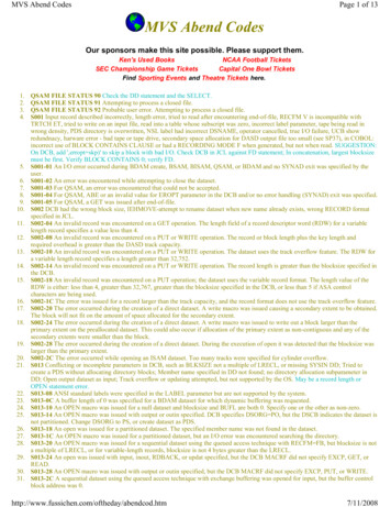
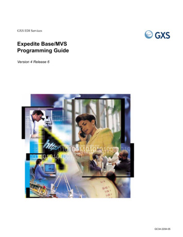
Single Node VLE ConfigurationFIGURE 1-1 shows a single node VLE configuration.FIGURE 1-1 Single Node VLE in a VSM SystemAs FIGURE 1-1 shows: Multiple TCP/IP connections (between the VTSS’s IP ports and the VLE’s IPports) are supported as follows: A single VLE can connect up to 8 VTSSs, so VTSSs can share VLEs. A single VTSS can connect to up to 4 VLEs to increase buffer space for heavyworkloads. A single VTSS can be attached to: Only RTDs Only other VTSSs (clustered) Only VLEs Any combination of the above. TCP/IP is the only supported protocol for connections between the VLE and theVTSS and for connections between the VLE and hosts running SMC and VTCS.What is Virtual Library Extension? 9
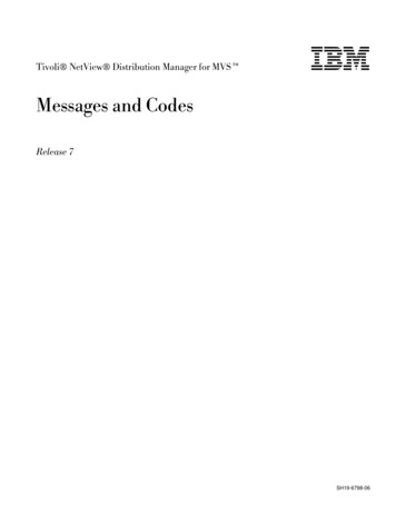
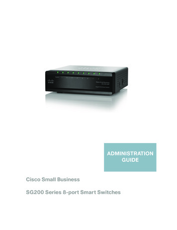
Multi-Node VLE Systems Multi-node VLE systems enable massive scaling of the VLE storage system.You can construct multi-node systems that can consist of one to 64 nodes, withmultiple nodes interconnected by a private network. A multi-node VLEappears to SMC/VTCS as a single VLE. A single VLE, therefore, can scalebetween 330 TB (for a single-node VLE with two JBODs) and 82.5 PB (for afully populated 64-node VLE).Note – These are effective capacities, assuming 4:1 compression.Also note that VLE is architected for up to 64 nodes, but has onlybeen validated for up to 7 nodes.FIGURE 1-2 on page 10 shows a VLE multi-node complex, where the nodes are crossconnected into a dedicated 10GE switch so that each node can access any other nodein the complex.FIGURE 1-2 VLE Multi-Node Complex10 Configuring the MVS Host Software for VLE
VTV EncryptionVLE to VLE Data TransferThe VLE storage system can manage data transfers independently of the VTSS, whichfrees VTSS resources for front-end (host) workload, which improves the overall VTSSthrough-put. For example: If your migration policies specify that there should be two VLE copies of a VTV(either in the same or separate VLEs), then the first migrate to a VLE will causedata to be transferred from the VTSS and all subsequent VLE migrates for the VTVmay be achieved via a VLE to a VLE copy. This reduces the VTSS cycle timesrequired to migrate all copies of a VTV. If your environment runs: VLE 1.2 or above, and VTCS 7.1 (with the supporting PTFs) or VTCS 7.2Then you can use VTCS to define more VLE devices than there are VTSS to VLEpaths via the CONFIG STORMNGR VLEDEV parameter. If you use this addressingscheme, then the VTSS resources used to migrate all the VTV copies to VLE arereduced even further because the path from the VTSS to the target VLE is onlyreserved when the data transfer is direct from the VTSS to the VLE. For all VLEVRTD actions, a path from the VTSS is only reserved when VTSS data transfer isrequired.VTV EncryptionThe encryption feature enables encryption of VMVCs written to the VLE system.Encryption is enabled on a per node basis, via an encryption key stored on the node,backed up on a USB device. Encryption is entirely managed via the VLE GUI; thehost software has no knowledge of encryption, as the VLE deencrypts VTVs that arerecalled to the VTSS.VTV DeduplicationDeduplication eliminates redundant data in a VLE complex. Deduplication, which iscontrolled by the STORCLAS statement DEDUP parameter, increases the effective VLEcapacity and is performed by the VLE before the VTV is written to a VMVC.To assess deduplication results, enable deduplication, monitor the results with theSCRPT report, and fine tune deduplication as necessary. The SCRPT report providesthe approximate “reduction ratio” for the deduplicated data, which is uncompressedGb divided by used Gb. The Reduction Ratio, therefore, includes both VTSScompression and VLE deduplication. A larger reduction ratio indicates moreeffective compression and deduplication.For example, the VTSS receives 16 Mb of data, compresses it to 4Mb, and writes thecompressed data to a VTV. VLE subsequently deduplicates the VTV to 2Mb andwrites it to a VMVC. Thus, the reduction ratio is 16Mb divided by 2Mb or 8.0:1.What is Virtual Library Extension? 11
Frame Size ControlEarly Time To First Byte (ETTFB)Early Time To First Byte (ETTFB), also known as the concurrent tape recall/mountfeature, allows the VTSS to use a VTD to read data as it being recalled from VLE: ETTFB is set globally via CONFIG GLOBAL FASTRECL. If CONFIG GLOBAL FASTRECL YES, you can disable ETTFB on per VTSS basisvia CONFIG VTSS NOERLYMNT.CONFIG GLOBALVLE.and CONFIG VTSS apply to both ETTFB for RTDs and ETTFB forFrame Size ControlFrame Size Control specifies the use of Jumbo frames on each copy link: If your TCP/IP network supports Jumbo Frames, enabling this option canimprove network performance. You enable Jumbo Frames via the Jumbo Frames check box on the Port CardConfiguration tab. Selecting this check box sets the MTU (MaximumTransmission Unit) value to 9000 for the port12 Configuring the MVS Host Software for VLE
Frame Size ControlWhat’s New With VLE 1.3?VLE 1.3 adds the following features: Reduced replication, which allows VTVs to be copied between VMVCs indeduplicated format. The only data copied is data that did not reside on thedestination node when the copy began. Reducing the amount of data copied,therefore, lowers network use and copy times.As described in “VTV Deduplication” on page 11, you enable deduplication ona Storage Class basis via the STORCLAS statement DEDUP parameter. Reducedreplication, therefore, works as follows: If deduplication is enabled for both the source and destination StorageClasses, then VTVs are copied in deduplicated format. This is the onlyconfiguration required for reduced replication. If deduplication is enabled for the source but not the destination StorageClass, then VTVs are “hydrated” (reconstituted) before being copied. If deduplication is enabled for the destination but not the source StorageClass, then VTVs are deduplicated when received at the destination. The VLE GUI now provides the ability to define static routes, which is simplerand less error-prone than the previous method (defining static routes viaSolaris commands).What is Virtual Library Extension? 13
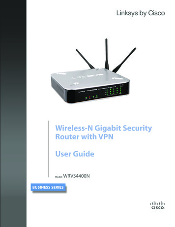
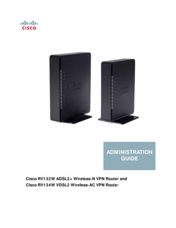
Frame Size ControlVLE Hardware and SoftwareThe VLE, which is a factory-assembled unit in a Sun Rack II Model 1242, consists ofthe following hardware: A server built on a Sun Server X2-4 platform. Four 1GigE ports for a combination of SMC UUI connections and serviceconnections. A service (ILOM) port. Four Quad-port 1GigE cards, which provide 16 ethernet ports for data transfer. J4410 JBODs in a ZFS RAID array, available in effective capacities of 330TB, 660TB,990TB, or 1320TB (assuming a 4 to 1 compression ratio when the data is migratedto the VLE). Two dual-port 10GigE NIC cards per server, which are required for the internalnetwork connections for VLEs with 3 or more nodes.The VLE software consists of: Oracle Solaris 11 Operating System. ZFS file system and MySQL database. The VLE application software.FIGURE 1-3 shows the VLE subsystem architecture.FIGURE 1-3 VLE Subsystem Architecture14 Configuring the MVS Host Software for VLE
Frame Size ControlAs FIGURE 1-3 on page 14 shows, the VLE application software is comprised of: HTTP/XML is the data protocol for host to VLE communications. The Universal User Interface (UUI) Request Handler, which processes UUIrequests from and produces responses to Storage Management Component (SMC)and Virtual Tape Control Software (VTCS). The UUI Request Handler determineswhich VLE components are used to service a request.UUI Request Handler calls: The PathGroup Manager to schedule VTV migrates and recalls. The PathGroupManager manages all Path Groups, where each Path Group manages a singleVTV data transfer between the VTSS and the VLE. The Storage Manager to schedule all report generation. The VLE Storage Manager component manages the VMVC/VTV data and metadata on the VLE. The VLE Storage Manager stores VTV data on and retrieves itfrom the ZFS on the JBOD array. TCP/IP/IFF is the data protocol for host to VLE communications, where the IP/IFF/ECAM component handles communications between the VTSS and the VLE.What is Virtual Library Extension? 15
Frame Size Control16 Configuring the MVS Host Software for VLE
2Configuring the MVS Host SoftwareThis chapter provides the MVS host software configuration for VLE as described inthe following sections: “Key Configuration Values” on page 18 “MVS Host Software Configuration Tasks” on page 20Configuring the MVS Host Software 17
Key Configuration ValuesThe following sections describes values required for software configuration that mustmatch values that are typically already set in the hardware configuration andrecorded in theIP and VMVC Configuration.xls worksheet.Subsystem NameThe subsystem name of the VLE, which is set by the VLE installation scripts, isspecified in the following: Either the VTCS CONFIG TAPEPLEX STORMNGR parameter or the CONFIGSTORMNGR NAME parameter. The VTCS CONFIG RTD STORMNGR parameter. The SMC STORMNGR NAME parameter. The SMC SERVER STORMNGR parameter. The HSC STORCLAS STORMNGR parameter.VTSS Ethernet Port AddressesThe VTSS Ethernet port addresses are required to configure the VTSS to VLE IPconnection via the CONFIG RTD IPIF parameter. For VSM5s, this value must matchthe values specified on the VSM5 IFF Configuration Status Screen. For VSM 6s, thismust be unique for each VTSS but does not correspond to an actual value on theVSM 6 TCP/IP ports.IP Addresses of VLE Ports for Host (UUI) CommunicationThese addresses are required for the SMC SERVER IP parameter.VMVC VolsersRequired to define VMVCs to SMC/VTCS, method of definition depends on thesoftware version, see “Defining the VLE VMVCs to the MVS Host Software andIncluding VMVCs in an MVC Pool” on page 25.VMVC Reclamation ThresholdFor more information, see“Specifying the Reclamation Policy for VMVCS”on page 24.18 Configuring the MVS Host Software for VLE
VTV DeduplicationThe STORCLAS DEDUP parameter specifies whether VTV data migrated to VMVCs inthe specified STORMNGR is deduplicated. For example:STORCLAS NAME(VLEDEDUP)STORMNGR(VLE1) DEDUP(YES)This STORCLAS statement specifies to deduplicate data in Storage Class VLEDEDUPthat is migrated to VLE1. For more information, see ELS 7.x Command, ControlStatement, and Utility Reference,Deduplication increases effective VMVC capacity and is performed by the VLE beforethe VTV is written to a VMVC. Oracle recommends, therefore, that you initiallyenable deduplication, then monitor the results with the SCRPT report and fine tunededuplication as necessary.Early Time to First Byte (ETTFB)ETTFB (also known as the concurrent tape recall/mount feature) allows hostapplications to read data while VTVs are being recalled from either VMVCs or RTDs.ETTFB is done by overlapping the VTV recall and mount phases, which allows theapplication to read the VTV data sooner. If the application attempts to read part ofthe VTV that has not been recalled, the application's I/O request is blocked until therequired VTV data is been recalled. With ETTFB for VLE, application access to thefirst byte occurs in under a second, making the VLE a true extension of the VTSS.Therefore, VLE ETTFB is a good choice for applications that serially access the VTVdata. VLE ETTFB is generally not a benefit for those applications that stack multiplefiles on a single VTV, including HSM and image management applications. In thesetypes of applications, the desired data is usually not at the beginning of the VTV, butrather at some random location in the VTV.ETTFB is disabled by default. You can globally enable ETTFB via the CONFIGGLOBAL FASTRECL parameter. If you globally enable ETTFB, you can disable it forindividual VTSSs via the CONFIG VTSS NOERLYMNT parameter.VTVs that have incurred a ETTFB recall error have an error flag set in their VTVrecord in the CDS. These VTVS are subsequently not selected for ETTFB. If you wantto reset the error flag, do any of the following: Enter a VTVMAINT SCRATCH(ON) command for the VTV. Migrate the VTV to a new MVC copy. Import the VTV. Create a new version of the VTV. Scratch the VTV.Configuring the MVS Host Software 19
MVS Host Software Configuration TasksAdding VLE to a VSM system requires the tasks described in the following sections: “Acquire the ELS supporting PTFs for VLE 1.3” on page 20 “Updating the SMC OMVS RACF Security Entry” on page 20 “Modifying the SMC SCMDS file” on page 21 “Updating the VTCS CONFIG Deck to Define VLE” on page 22 “Defining the VLE VMVCs to the MVS Host Software and Including VMVCs inan MVC Pool” on page 25 “Updating the MVS Host Software Policies” on page 26For more information on the commands and control statements referenced in thischapter, see ELS 7.x Command, Control Statement, and Utility Reference.Acquire the ELS supporting PTFs for VLE 1.3For ELS 7.2, support is included in the base level. For ELS 7.0 and 7.1, get the latestSMP/E receive HOLDDATA and PTFs described in TABLE 2-1 and SMP/E APPLY withGROUPEXTEND.TABLE 2-1 ELS Supporting PTFs for VLE 1.3ELS 7.0ELS 7.1L1H16C1L1H16J6L1H1672L1H1674Updating the SMC OMVS RACF Security EntryThe VLE requires SMC to have an OMVS RACF security entry in order to have aTCP/IP connection to the host.OMVS is a segment associated with the RACF userid. The SMC started task musthave a userid associated with OMVS, either in the RACF STARTED class definition orthe ICHRIN03 LNKLST module. The userid associated with the SMC task needs tohave an OMVS segment defined to it within RACF as follows:ADDUSER mber))Or, if the userid already exists but does not have an OMVS segment:ALTUSERuserid OMVS(UID(uidnumber))20 Configuring the MVS Host Software for VLE
Modifying the SMC SCMDS fileSMC manages all communication between VTCS and VLE, so SMC must know howto connect to the VLE server. You do so by adding an SMC STORMNGR statement foreach VLE system plus one or more SMC SERVER statements that define the TCP/IPcontrol paths for the VLE. For 7.0 and above, you may want to do this in your SMCCMDS file as shown in CODE EXAMPLE 2-1.TAPEPLEX NAME(TMVSA)LOCSUB(SLS0)SERVER NAME(ALTSERV) TAPEPLEX(TMVSA) HOSTNAME(MVSX) PORT(8888)STORMNGR NAME(VLE1)SERVER NAME(VLESERV1) STORMNGR(VLE1)IP(192.168.1.10)PORT(60000)CODE EXAMPLE 2-1 SMC Commands for VLECODE EXAMPLE 2-1 contains: A TAPEPLEX statement, which defines a single TapePlex, TMVSA, with an HSC/VTCS running on the same MVS host (SLS0). A SERVER statement, which defines a backup HSC/VTCS subsystem(ALTSERV) running on another host. A STORMNGR command that defines a VLE (VLE1). A second SERVER command that defines a UUI communication path to theVLE, where: The server name is VLESERV1. The STORMNGR parameter value is VLE1. The IP parameter value is the VLE port IP address of 192.168.1.10 for UUIcommunications. The PORT parameter value is 60000; this value is always used for theSERVER PORT parameter for SMC communication with a VLE.Configuring the MVS Host Software 21
Updating the VTCS CONFIG Deck to Define VLEYou must update VTCS CONFIG deck to define the VLE and the connectivity fromthe VTSS systems to the VLE. VTCS can drive VLE 1.3 as follows: For VTCS 7.0 and above, the CONFIG TAPEPLEX statement defines the TapePlexthat VTCS is running under and provides the list of defined VLEs on the CONFIGTAPEPLEX STORMNGR parameter as shown in CODE EXAMPLE 2-2.TAPEPLEX THISPLEX TMVSA STORMNGR VLE1VTSS NAME VTSS1 LOW 70 HIGH 80 MAXMIG 8 MINMIG 4 RETAIN 5RTDPATHNAME VL1RTD1 STORMNGR VLE1 IPIF 0A:0RTDPATHNAME VL1RTD2 STORMNGR VLE1 IPIF 0A:1RTDPATHNAME VL1RTD3 STORMNGR VLE1 IPIF 0I:0RTDPATHNAME VL1RTD4 STORMNGR VLE1 IPIF 0I:1RTDPATHNAME VL1RTD5 STORMNGR VLE1 IPIF 1A:0RTDPATHNAME VL1RTD6 STORMNGR VLE1 IPIF 1A:1RTDPATHNAME VL1RTD7 STORMNGR VLE1 IPIF 1I:0RTDPATHNAME VL1RTD8 STORMNGR VLE1 IPIF 1I:1VTD LOW 6900 HIGH 69FFCODE EXAMPLE 2-2 VTCS 7.0 CONFIG VLE ExampleIn CODE EXAMPLE 2-2, note: The CONFIG TAPEPLEX statement, which defines TMVSA as the TapePlex thatVTCS is running under and the names of all connected VLEs (which in thisexample is a single VLE called VLE1). The CONFIG RTDPATH statements, which define a single VLE RTD for eachpath from the VTSS to the VLE. In this example, the CONFIG RTDPATHstatements for VTSS1 specify: The name of the RTDPATH. The connections to the defined VLEs (STORMNGR VLE1). The IPIF value for each VTSS to VLE port connection in ci:p format where: c is 0 or 1. i is A or I. p is 0 through 3.Note – For VSM5s, this value must match the values specified onthe VSM5 IFF Configuration Status Screen. For VSM 6s, this mustbe unique for each VTSS but does not correspond to an actualvalue on the VSM 6 TCP/IP ports.22 Configuring the MVS Host Software for VLE
VTCS 7.1 and above systems can, of course, drive VLE 1.3 as VTCS 7.0 does asdescribed on page 22. In this mode, however, the number of VLE RTD targets islimited by the number of paths from a VTSS. Additionally, the VLE RTDs areassigned to fixed VTSS paths. The path from a VTSS to the VLE is always reservedby VTCS regardless of whether any VTSS to VLE data transfer is occurring.However, with VTCS 7.1 (with the PTFs described in TABLE 2-1 on page 20) andabove, you can define a VLE with more VLE RTD targets then there are pathsfrom the VTSS to the VLE, which means: The path from the VTSS to the VLE is not reserved unless a VTSS to VLEdata transfer is required. More VLE RTD operations can occur simultaneously. For example, an auditof a VMVC does not require data transfer between the VTSS and the VLE.As shown in CODE EXAMPLE 2-3, the VLEs are defined via a CONFIG STORMNGRstatement, not the CONFIG TAPEPLEX STORMNGR parameter. The CONFIGSTORMNGR statement specifies the VLEs that VTCS connects to. Additionally, foreach VLE, the CONFIG STORMNGR VLEDEV parameter defines the number and thenames of the RTD devices that the VLE emulates. The more devices defined (up tothe maximum of 96 devices per VLE), the greater the level of concurrent activitiesVTCS can schedule on the VLEs.TAPEPLEX THISPLEX TMVSCSTORMNGR NAME VLE1 VLEDEV(S000-S05F)STORMNGR NAME VLE2 VLEDEV(S000-S05F)VTSS NAME VTSS1 LOW 70 HIGH 80 MAXMIG 8 MINMIG 4 RETAIN 5RTDPATHNAME VL1RTD1 STORMNGR VLE1 IPIF 0A:0RTDPATHNAME VL1RTD2 STORMNGR VLE1 IPIF 0A:1RTDPATHNAME VL1RTD3 STORMNGR VLE1 IPIF 0I:0RTDPATHNAME VL1RTD4 STORMNGR VLE1 IPIF 0I:1RTDPATHNAME VL1RTD5 STORMNGR VLE2 IPIF 1A:0RTDPATHNAME VL1RTD6 STORMNGR VLE2 IPIF 1A:1RTDPATHNAME VL1RTD7 STORMNGR VLE2 IPIF 1I:0RTDPATHNAME VL1RTD8 STORMNGR VLE2 IPIF 1I:1VTD LOW 6900 HIGH 69FFCODE EXAMPLE 2-3 VTCS 7.1 CONFIG VLE ExampleIn CODE EXAMPLE 2-3 on page 23, note: The CONFIG TAPEPLEX statement now simply defines TMVSC as the TapePlexthat VTCS is running under. It does not define the connected VLEs. The CONFIG STORMNGR statements, which define the VLEs configured in thissystem - VLE1 and VLE2 in this example. These statements also specify thenumber of VLE devices via the VLEDEV parameter. In this example, each VLEhas the maximum of 96 emulated devices, which allows VTCS to schedule upto 96 processes on each VLE. The VLE device addresses are in the form of Sxxx(where xxx is a hexadecimal value. For example, S000-S05F represents 96emulated devices.Configuring the MVS Host Software 23
The CONFIG RTDPATH statements for VTSS1, which specify: The name of the RTDPATH. The connections to the defined VLEs (STORMNGR VLE1,STORMNGR VLE2). The IPIF value for each VTSS to VLE port connection in ci:p format where: c is 0 or 1. i is A or I. p is 0 through 3.Note – For VSM5s, this value must match the values specified onthe VSM5 IFF Configuration Status Screen. For VSM 6s,this must be unique for each VTSS but does not correspond to anactual value on the VSM 6 TCP/IP ports.Specifying the Reclamation Policy for VMVCSVLE MVC media (VMVCs) is subject to fragmentation and must be reclaimed justlike real MVCs. The VMVC reclaim process, however, uses far fewer resources than astandard reclaim. The reclaim threshold for a VMVC is specified via the CONFIGRECLAIM VLTHRES parameter. The lower that you set VLTHRES, the more frequentVTCS will run reclaim on the VMVCs and the greater the effective capacity of theVMVS (less fragmentation).24 Configuring the MVS Host Software for VLE
Defining the VLE VMVCs to
10 Configuring the MVS Host Software for VLE Multi-Node VLE Systems † Multi-node VLE systems enable massive scaling of the VLE storage system. You can construct multi-node systems that can consist of one to 64 nodes, with multiple nodes interconnected by a private network. A multi-node VLE appears to SMC/VTCS as a single VLE.