Transcription
RADIANT CEILING PANELSSLC / SMCTECHNICAL CATALOGMANUFACTURERS OF HYDRONIC HEATING AND COOLINGCOMMERCIAL & INDUSTRIALsigmaproducts.com T. 905.670.3200 F. 905.670.3822
SIGMA RADIANT PANEL SYSTEMS SLC/SMCTABLE OF CONTENTSPRODUCT OVERVIEW & DESIGN CONSIDERATIONS 5SLC LINEAR RADIANT CEILING PANELS. 9Unit Specifications .10Capacity Data .12Dimensions & Weights .14Pressure Drop Data .15Standard Shapes .17Installation Detail Diagrams .19Conceptual Renderings .28Guide Specifications .42SMC MODULAR RADIANT CEILING PANELS. 45Unit Specifications .47Capacity Data .48Dimensions & Weights .50Guide Specifications .52sigmaproducts.com 905.670.32003
SIGMA RADIANT PANEL SYSTEMS SLC/SMCPRODUCT OVERVIEWWith an abundance of styles and configurations, a Sigma Radiant Panel selection is sure to meetboth the design needs of architects and performance needs of the mechanical engineer.Performance data for radiant hydronic heating panels has been verified by independent testing atthe University of Waterloo in Ontario, Canada. Standard finish is textured white to match angle/teemouldings normally used for acoustic ceiling tile type installations. Custom finishes are available,and modular panels can also be silkscreened to simulate acoustic ceiling tile patterns.SLC Sigma Linear Ceiling PanelsLinear aluminum extruded panels with a castellatedsmooth face profile are available in a variety of widthsand lengths to accommodate the perimeter planning ofany building ceiling, including acoustic ceiling tile,drywall, or bulkhead ceiling types. Panel widths aremanufactured to fit into standard T-bar systems, and arealso available with extruded T-frames for mounting intodrywall or bulkhead ceiling applications.SMC Sigma Modular Ceiling PanelsModular drop-in panels are available in standard 2’ x 2’and 2’ x 4’ sizes, as well as custom sizes, for easymounting into new or existing ceiling grids.BASIC PRINCIPLESLike the sun, radiant panels transfer energy directly toany surface the panel “sees”, much the same way thatthe sunshine illuminates a room. The uniformity oftemperatures comes from the natural absorption and reradiation of energy between all interior surfaces.Radiant heat travels in straight lines until it reaches asolid object. The heat warms that object and is reradiated to nearby colder objects. Unlike convective heatwhich is actually a current of warm air, radiant heat doessigmaproducts.com 905.670.3200not rise. The floor is kept as warm as all other absorbingsurfaces. Through this silent, non-mechanical process,radiant heating panels create a thermal barrier at theperimeter of the building providing a uniform draftlesswall of warmth. This system provides an excellentintegrated building heating/cooling design. The entireceiling and all surfaces exposed to the radiant panelsbecome part of the heating/cooling system by absorbingand re-radiating heat, providing a comfortableenvironment.5
SLC/SMC SIGMA RADIANT PANEL SYSTEMSPRODUCT OVERVIEWUnlike conventional HVAC systems, radiant heatingpanels do not rely on room temperature. The criticaldesign parameter is the difference between the meanpanel temperature and the average unheatedtemperature of all surfaces within the space. If theaverage unheated surface temperature (AUST) and thetemperature of the air in a room equals the mean paneltemperature (MPT), there will be no net heat transfer.When the AUST falls below the MPT, the panels radiateenergy into the room. The energy radiated does notdirectly warm the air, but rather warms the glass/walls/furniture/floors and people inside of the room. Theseobjects in turn warm the air.The mean radiant temperature within a space is one ofthe most important factors influencing occupantcomfort. Sigma Radiant Panels affect the mean radianttemperature directly by raising the surface temperaturesin the space, and thereby providing occupants withsuperior control of ambient conditions.DESIGN CONSIDERATIONSRadiant heating design is similar to that of conventionalhydronic heating systems. Zone thermostats supply hotwater to panels that respond instantaneously to give thespace the necessary heating. Piping is located in theceiling plenum which is usually readily accessible.As the panels raise the Mean Radiant Temperature inthe space, they make occupants more comfortable atambient temperatures lower than those required ofconvective systems. Consequently, Sigma recommendsan inside dry bulb temperature 3 to 4 Deg F below thatnormally used with convective systems.Room loads should be calculated in the normal manner,using the ASHRAE guide. Calculations based onexcessive factor of safety room loads should not beused, because such assumptions result in excessivepanel width being specified. Using too wide a panel forthe application reduces both effectiveness andefficiency of the system.Sigma utilizes 5/8” OD (1 2” nominal) copper tube,allowing for the use of standard plumbing fittings. All U-6bends and spiral panel interconnectors (to connect multi-panel circuits together) are expanded so that nocouplers are required. Access panels are easy to specify,and are essentially separate, removable, radiant panelswith no copper. This provides the installer and owner ameans to access the hot water supply and hot waterreturn connections in drywall or bulkhead ceilingconfigurations. To properly access a given ceiling, Sigmarecommends that access panels be at least 12 incheslong. Note that designers should account for heatingcapacity reduction due to access panel insertion into abuilding design. For example, if the wall to walldimension of a room is 10 feet, and an 18” long accesspanel is used, then the maximum active copper length isreduced from 10 Feet to 8.5 Feet. If the room requires4000 Btuh of heat, then the panel must supply 4000Btuh/8.5 feet 471 Btuh/lineal feet. For the room withan acoustic ceiling tile-type ceiling, and no access panel,only 400 Btuh/lineal feet is required. Once the Btuh/lineal feet is correctly established, use the capacitycharts to ascertain the specific Sigma radiant panel thatworks for you.DESIGN EXAMPLE(A) Determine the heat lossCalculate the realistic heat loss of the perimeter usingstandard ASHRAE methods. As explained above, do notuse excessive safety factors. In this design example weshall use a heat loss of 8500 Btuh.(B) Determine the available length of panel per zoneRadiant heating panels should run continuously alongthe perimeter of a room or area. Sometimesobstructions such as building columns, partition walls,or changes in direction influence the available length ofactive panel (i.e. panel where copper can be installed).Typical column spacings in buildings are 20 to 30 feet.Generally, using the longest panel length is mosteconomical and efficient. Bear in mind, however, thatwhile Sigma can produce panels up to 14 feet long,these are extremely awkward to handle (especially forwidths over 24”). Both the Sigma factory and, moresigmaproducts.com 905.670.3200
SIGMA RADIANT PANEL SYSTEMS SLC/SMCPRODUCT OVERVIEWimportantly, the jobsite installation personnel will haveissues with bowing and weight. For this reason, Sigmarecommends maximum panel lengths of 13 feet.As an example, assume a building has 24” squarecolumns spaced on 26 foot centres. The available panellength is reduced to 24 feet, and this would typically besupplied as two 12 foot panels.(C) Determine the available length of panel per zoneDividing the heat loss from (A) by the available panellength from (B) gives the required capacity in Btuh/Lineal foot or Watts/Metre. For a given Average WaterTemperature , simply choose the panel configurationthat meets the required capacity. For example, assumea heat loss of 8,500 Btuh for each 26 foot bay. Thisgives 8500/24 354 Btuh/Lineal Foot.(E) Calculate design water temperature dropUsing 2 of the 18-3 pass panel; each panel is 18 incheswide by 12 feet long. The panels are interconnected usingSigma spiral panel interconnectors.Each panel is 12 ft. x 3 pass 36 ft. copper/panel2 panels: 2 x 36ft 72ft. straight copper.3 interconnectors between the 2 panels.@ 0.85 USGPM, we interpolate from the Pressure DropChart in Section 5. E.(Page 15):Pressure Drop in ft. H2O/100ft. 1.4Interconnector Pressure Drop in ft. H2O 0.125Therefore:From the Sigma capacity tables at an assumed AverageWater Temperature of 180 deg. F, choose 18-6 passradiant panel which gives 406 Btuh/Lineal foot. Notethat a 6 pass panel requires same end Hot WaterSupply/Return connections. If opposite end connectionsare required, and for simplicity, assuming the AverageWater Temperature was 190 deg. F, the 18-3 passradiant panel with a capacity of 379 Btuh/Lineal Footwould be chosen. Note that the Sigma capacity tables donot show every possible available capacity, and someinterpolation is required. For example, 24-6 pass can beinterpolated between 24-4 pass and 24-8 pass. Contactyour local representative if you require specificcalculations.(D) Calculate design water flowThe water flow rate is calculated from:USGPM Heat Loss (Btuh) / (500 x WTD)Where WTD Water Temperature Drop in this example,the heat loss is 8500 Btuh and with a desired WTD 20deg. Fsigmaproducts.com 905.670.32007
SIGMA RADIANT PANEL SYSTEMS SLC/SMCSLCLINEARRADIANT CEILING PANELSsigmaproducts.com 905.670.32009
SLC/SMC SIGMA RADIANT PANEL SYSTEMSSLC UNIT SPECIFICATIONSOVERVIEWSigma Linear Radiant Panels are generally used inapplications where hydronic heating is required for wallsadjacent to building exteriors, also known as perimeterwalls. Linear panels have a castellated or smooth face,and Sigma offers, but is not limited to, a variety ofstandard extrusions. The extrusions can beinterchanged to provide an end product that is tailoredto the customer requirements, whether this be a simple,flat (2-Dimensional) panel used for T-Bar type ceilings, ormore architecturally pleasing designs such as exposedceilings, nominal panel widths start at 4”, and continuein increments of 2” to virtually any width required. Aswell, Sigma provides 6” extrusions with either 1 or 2copper saddles allowing the density of copper to doublefor a given panel width. This allows for an increase inheating capacity given a fixed panel width application.As such, Sigma Radiant Panels are a flexible, efficient,and aesthetically pleasing solution for your hydronicheating needs.CONSTRUCTIONSigma Linear Radiant Panels are constructed fromaluminum-extruded planks in a variety of profiles. Eachextrusion type has been designed with the same tongueand groove detail to facilitate interchangeability with allother extrusions. After panel lengths are identified, thenecessary extrusions are cut into planks, which simplysnap together longitudinally. A small screw is drilled atthe plank interfaces, and this, combined with other clips,provides necessary rigidity to the panel. In order toreduce the amount of field work required, all of thisconstruction occurs at the Sigma factory and arrives onsite as a completed panel cut to the customer-specifiedlength.10Once the planks are cut and assembled, they are readyfor painting. The exposed surface of the panel is paintedwith a specially formulated polyurethane powder paint toprovide a textured low gloss finish, capable ofwithstanding the requirements inherent with thermalcycling. After painting, a non-hardening Heat TransferPaste is applied at the interface between the copper andthe aluminum saddle, which is an integral part of theextrusion.The straight copper tubes associated with the specificRadiant panel are placed into aluminum saddles afterthe heat transfer paste has been applied. As an optionSigma can also pre-solder and pressure test theserpentine copper circuit at this stage. All ends ofcopper that require site connection, such as Hot Watersupplies, Hot Water Returns, or interconnections toother panels on long circuits, are bent up at a slightangle at the factory.In order to provide a uniform contact area betweencopper and aluminum, the copper circuit is attached tothe aluminum saddles via special clips spaced amaximum of 24” apart. Cross Braces are added onto theRadiant Panel to facilitate site installation via wirehangers or alternate mounting methods. Finally, Sigmaplaces labels onto the panel to indicate the panelorientation (female side of panel facing perimeter wall),as well as to identify the panel as per the Sigmadocumentation submittal. This same identifying label isaffixed onto the product when it is brown-wrapped andultimately placed vertically onto a skid for shipping tothe customer.sigmaproducts.com 905.670.3200
SIGMA RADIANT PANEL SYSTEMS SLC/SMCSLC UNIT SPECIFICATIONSMATERIAL SPECIFICATIONPANEL — Extruded Aluminum, various profiles, castellated or smooth on the exposed side, with identical tongueand groove design for interchangeability. Copper Saddleis integral to each extrusion. Contact us for other extrusions not shown in this catalogue.SIZES — Panel widths from 4” and up, in increments of2”. Bullnose, Channel extrusions available for 3-D applications. Panel Lengths custom cut to customer requirements.PAINT — Standard is Sigma Radiant Panel White(“RPTXT2” color) Polyurethane-Polyester Formulation inTextured White. Contact us for custom colour options.COPPER — 5/8” (16 mm) Outside Diameter, tempered.Standard is straight copper pre-bent at customer Hotwater Supply/Return locations, and u-bends suppliedloose for field installation. Optionally: copper can be presoldered and tested at factory. Copper is held down tointegral aluminum panel saddle via zinc-plated springsteel clips, with non-hardening heat transfer paste applied between copper and saddle.SUSPENSION — Mounting frame is not included instandard orders. A custom option is 1” wide x 2” high x1/16” thick aluminum extruded T-Frame, mechanicallyclinched by Sigma, used generally for drywall type ceilings with 3” clearance to all walls. As well, Sigma stocks1’ wide x 2” high x 1/16” thick aluminum tee (144”lengths0 and 1” x 1”x 1/16” thick aluminum Angle(126” lengths) for LOOSE framing requests, generallywall to wall applications.INSULATION — Standard is NO Insulation. Option: 1” or2” Foil Faced Batt Insulation installed at factory, dependent on Customer Mechanical Specification. Insulation can be foil faced one side only, or completely ENCAPSULATED.WEIGHT — Dependent on copper tube density. Use awet weight of 2.5 Lbs/Sq.Ft (12.2 kg/Sq.Mtr) when calculating requirements for suspension of panels to building structure.SUPPORT — Extruded aluminum channel cross bracesspaced every 36” maximum.sigmaproducts.com 905.670.320011
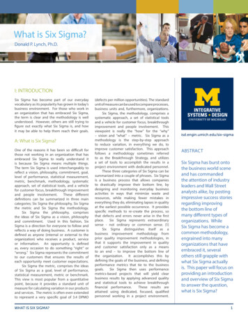
SLC/SMC SIGMA RADIANT PANEL SYSTEMSSLC CAPACITY DATAIMPERIALMean Water Temperature (Degrees F)NOMINAL Panel Width (inches) - Tube 45606387817659658741064Heating capacities are shown in Btuh/Lineal ft. and are based on 700F Room temperature. For every 10F decreasein Room temperature below 700F, the output increases by 0.9%. For every 10F increase in Room temperatureabove 700F the output decreases by 0.9%12sigmaproducts.com 905.670.3200
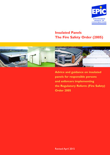
SIGMA RADIANT PANEL SYSTEMS SLC/SMCSLC CAPACITY DATAMETRICMean Water Temperature (Degrees C)NOMINAL Panel Width (millimetres) - Tube 8401023Heating capacities are shown in Watts/Lineal Metre and are based on 210C Room temperature. For every 10Cdecrease in Room temperature below 210C, the output increases by 2%. For every 10C increase in Room airtemperature above 210C the output decreases by 2%sigmaproducts.com 905.670.320013
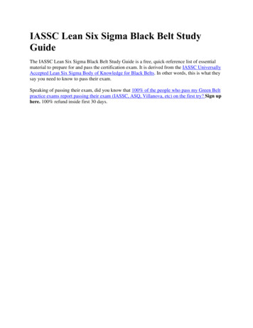
SLC/SMC SIGMA RADIANT PANEL SYSTEMSSLC DIMENSIONS & WEIGHTSUnit ModelNOMINAL WidthActual PanelCeiling OpeningWeightWidth-TubesInches (mm)WidthSIGMA T-Frames(operating)Inches (mm)“B”lbs./ft. (kg/m)“A”6-1 andNumber of Panels6-2PanelWidth of each12-2Ceiling Opening Width0.7SIGMA(1.04 kg/m)forsupplied6”(152.4mm)6.082” (154.5mm)6.582”"A"(166.5 mm)NominalPanel WidthActualPanel Width0.9Frame(1.34 kg/m)'Tee'for Drywall"B"12” (304.8 mm)11.977” (304.2mm) 12.477” (316.2 mm)inches (mm)inchesmminchesmminchesmm12-41 @ 6 (152)6152.46.082154.56.582166.51.5 (2.23 kg/m)1.8 (2.68 kg/m)2 @ 418-3(203)8203.27.977202.68.477214.618” (457.2 mm)17.872” (453.9 mm) 18.372” (465.9 mm)18-62 @ 6 (304)12304.811.977304.212.477316.22.2 (3.27 kg/m)3 @ 624-4(457)18457.217.872453.918.372465.92.9 (4.31 kg/m)4 @ 624-8(610)24609.623.767603.724.267615.73.6 (5.35 kg/m)24” (609.6 mm)23.767” (603.7 mm) 24.267” (615.7 mm)5 @ 6 (762)3076229.662753.430.162765.42.7 (4.01 kg/m)30-53.6 (5.35 kg/m)30-104.5 (6.69 kg/m)30” (762 mm)29.662” (753.4 mm) 30.162” (765.4 mm)6 @ 6 (914)36914.435.557903.136.057915.136-636-1236” (914.4 mm)35.557” (903.1 mm) 36.057” (915.1 mm)4.4 (6.54 kg/m)5.4 (8.02 kg/m)1.Dimensions in Table 1 are sample widths. Nominalpanel widths from 4” to 48” are available in 2 inchincrements.3. Sigma supplied perimeter T-Frames are constructedwith T aluminum extrusions. Opening dimensions are forSigma supplied Frames only.2. For panel lengths, allow a minimum of .187”(5 mm)for expansion clearance from end of panels to inside ofTee.4. For customer-supplied frames allow min .125”(3mm)width clearance between the edge of the panel and theinner edge of the frame for expansion. Allowminimum .187” (5mm) length clearance between theedge of the panel and the inner edge of the frame.14sigmaproducts.com 905.670.3200
SIGMA RADIANT PANEL SYSTEMS SLC/SMCSLC PRESSURE DROPIMPERIALFlow RateVelocityPressure DropInterconnector(GPM)(ft/s)(ft. H2O per 100ft of(ft. of TRICPressure DropFlow com 905.670.3200(kPa/15m of StraightCopper)Interconnector(kPa)15
SLC/SMC SIGMA RADIANT PANEL SYSTEMSSLC PRESSURE DROP — EXAMPLESExample 1:*PDC from Pressure Drop Chart (Page 15)@ 1GPM, Single Panel Serpentine.16 ft. x 4 pass 64 ft. @ 2 ft. H2O/100 ft. (PDC) 1.28 ft. H2O 3.83 kPaS RPlease note the U-bends are considered negligible when calculating overall pressure drop.Example 2:@ 1GPM, Double Panel Serpentine.S R16 ft. x 4 pass 64 ft. @ 2 ft. H2O/100 ft. (PDC) 4 Interconnections x 0.168 ft. H2O (PDC) 1.28 ft. H2O 0.672 ft. H2O 1.95 ft. H2O 5.83 kPaExample 3:@ 1GPM (or 0.5 GPM/circuit), DoublePanel Parallel-flow Serpentine.SR1616 ft. x 2 pass/circuit 32 ft./circuit @ 0.5GPM- 0.5 ft. H2O/100 ft. (PDC) 2 Interconnections x 0.05 ft. H2O (PDC) 0.16 ft. H2O 0.1 ft. H2O 0.26 ft. H2O 0.78 kPasigmaproducts.com 905.670.3200
SIGMA RADIANT PANEL SYSTEMS SLC/SMCSLC STANDARD SHAPESSTANDARD FLAT EXTRUSIONSNOTESPanels can be constructed at any width, in 2” increments, starting at 4”.Dimensions shown in inches (mm)Castallated finish shown; also available in smooth-face for type 6-2 above.sigmaproducts.com 905.670.320017
SLC/SMC SIGMA RADIANT PANEL SYSTEMSSLC STANDARD SHAPESSTANDARD MISCELLANEOUS EXTRUSIONS18sigmaproducts.com 905.670.3200
SIGMA RADIANT PANEL SYSTEMS SLC/SMCSLC INSTALLATION DETAIL1. SINGLE PANEL CIRCUITRYsigmaproducts.com 905.670.320019
SLC/SMC SIGMA RADIANT PANEL SYSTEMSSLC INSTALLATION DETAIL2. MULTIPLE PANEL CIRCUITRYParallel flow in even pass panels reduce pressuredrop for long zones. SIGMA designs for 21 kPa (7ft. H2O) maximum pressure drop, unless otherwisenoted by customer.20sigmaproducts.com 905.670.3200
SIGMA RADIANT PANEL SYSTEMS SLC/SMCSLC INSTALLATION DETAIL3. FULL T-BAR [FTBAR]Dimensions shown in inches [mm]sigmaproducts.com 905.670.320021
SLC/SMC SIGMA RADIANT PANEL SYSTEMSSLC INSTALLATION DETAIL4. PARTIAL T-BAR [PTBAR]Dimensions shown in inches [mm]22sigmaproducts.com 905.670.3200
SIGMA RADIANT PANEL SYSTEMS SLC/SMCSLC INSTALLATION DETAIL5. BULKHEAD [BULK]Dimensions shown in inches [mm]sigmaproducts.com 905.670.320023
SLC/SMC SIGMA RADIANT PANEL SYSTEMSSLC INSTALLATION DETAIL8. DRYWALL [DWAL]Dimensions shown in inches [mm]* Customer supplied perimeter frame. Note that SIGMA supplied perimeter framesDO NOT span from wall to wall—refer to page 27.24sigmaproducts.com 905.670.3200
SIGMA RADIANT PANEL SYSTEMS SLC/SMCSLC INSTALLATION DETAIL9. COPPER CIRUITRYDimensions shown in inches [mm]sigmaproducts.com 905.670.320025
SLC/SMC SIGMA RADIANT PANEL SYSTEMSSLC INSTALLATION DETAIL10. CLEARANCESDimensions shown in inches [mm]26sigmaproducts.com 905.670.3200
SIGMA RADIANT PANEL SYSTEMS SLC/SMCSLC INSTALLATION DETAIL11. SIGMA FRAME OPENINGSNumber of Panels andNumber of Panels Nominal Panel WidthActual Panel Width "A"Width of each PanelNOMINALActual Panel Width width of eachpanelPanel Widthinches (mm)inchesmminchesmminchesmmInches (mm)Inches (mm)“A”Ceiling Opening Widthfor SIGMA suppliedCeiling Opening “B”'Tee' Frame for Drywall(Sigma-supplied T"B"Frame)Inches (mm)Inches (mm)@ 6 (152)6 (152.4)2 @ 41 (203)8203.27.977202.68.477214.66.082 (154.5)6.582 (166.5)@ 4 (203)8 (203.2)2 @ 62 (304)12304.811.977304.212.477316.27.977 (202.6)8.477 (214.6)3 @ 62 (457)18457.217.872453.918.372465.9@ 6 (304)12 (304.8)11.977 (304.2)12.477 (316.2)17.872 (453.9)18.372 (465.9)23.767 (603.7)24.267 (615.7)1 @ 6 (152)6152.46.082154.56.582166.54 @ 6 (610)24609.623.767603.724.267615.73 @ 6 (457)18 (457.2)5 @ 6 (762)3076229.662753.430.162765.4@ 6 (610)24 (609.6)6 @ 64 (914)36914.435.557903.136.057915.15 @ 6 (762)30 (762)29.662 (753.4)30.162 (765.4)6 @ 6 (914)36 (914.4)35.557 (903.1)36.057 (915.1)NOTE:1. Above are sample panel widths. Nominal panel widths starting from 4” are available (in 2” increments).2. For panel lengths, allow 0.25” (6mm) for clearance from end of panel to inside of tee.3. Sigma supplied frames are constructed of Type T aluminum extrusions, 2” high x 1” wide x 1/16” thick.Wall-to-Wall Sigma frames are not available—DRYWALL OPENING MUST BE LESS THAN WALL-TO-WALLDIMENSION.4. For customer supplied frames, all minimum 3mm width clearance from end of panel to frame structure(both sides). Allow minimum 4mm length clearance (both sides).sigmaproducts.com 905.670.320027
SLC/SMC SIGMA RADIANT PANEL SYSTEMSSLC CONCEPTUAL DETAIL1. STANDARD PANEL IN ACOUSTIC CEILING TILEDimensions shown in inches [mm]28sigmaproducts.com 905.670.3200
SIGMA RADIANT PANEL SYSTEMS SLC/SMCSLC CONCEPTUAL DETAIL2. RADIANT PANEL IN DRYWELL CEILING*Perimeter frame by others. Note that SIGMA supplied framesDO NOT span from Wall to Wallsigmaproducts.com 905.670.320029
SLC/SMC SIGMA RADIANT PANEL SYSTEMSSLC CONCEPTUAL DETAIL3. RADIANT PANEL CEILING SURFACE MOUNTEDDimensions shown in inches [mm]30sigmaproducts.com 905.670.3200
SIGMA RADIANT PANEL SYSTEMS SLC/SMCSLC CONCEPTUAL DETAIL4. HANGING RADIANT PANEL WITH BULLNOSEDimensions shown in inches [mm]sigmaproducts.com 905.670.320031
SLC/SMC SIGMA RADIANT PANEL SYSTEMSSLC CONCEPTUAL DETAIL5. EXPOSED HANGING RADIANT PANELDimensions shown in inches [mm]32sigmaproducts.com 905.670.3200
SIGMA RADIANT PANEL SYSTEMS SLC/SMCSLC CONCEPTUAL DETAIL6. EXPOSED HANGING RADIANT PANEL WITH FRAMEDimensions shown in inches [mm]sigmaproducts.com 905.670.320033
SLC/SMC SIGMA RADIANT PANEL SYSTEMSSLC CONCEPTUAL DETAIL7. SECURITY ENCLOSURE WITH TORX FASTENERSDimensions shown in inches [mm]34sigmaproducts.com 905.670.3200
SIGMA RADIANT PANEL SYSTEMS SLC/SMCSLC CONCEPTUAL DETAIL8. SECURITY ENCLOSURE WITH CAM LOCK TO PREVENT PANELS FROM BEING LIFTEDDimensions shown in inches [mm]sigmaproducts.com 905.670.320035
SLC/SMC SIGMA RADIANT PANEL SYSTEMSSLC CONCEPTUAL DETAIL9. RADIANT PANEL (FIELD CUT) TO ACCOMMODATE A COLUMNDimensions shown in inches [mm]36sigmaproducts.com 905.670.3200
SIGMA RADIANT PANEL SYSTEMS SLC/SMCSLC CONCEPTUAL DETAIL10. RADIANT PANEL (BULKHEAD) WITH LINEAR SLOT DIFFUSERDimensions shown in inches [mm]sigmaproducts.com 905.670.320037
SLC/SMC SIGMA RADIANT PANEL SYSTEMSSLC CONCEPTUAL DETAIL11. RADIANT PANEL (T-BAR) WITH LINEAR SLOT DIFFUSERDimensions shown in inches [mm]38sigmaproducts.com 905.670.3200
SIGMA RADIANT PANEL SYSTEMS SLC/SMCSLC CONCEPTUAL DETAIL12. SLOPED RADIANT PANELDimensions shown in inches [mm]sigmaproducts.com 905.670.320039
SLC/SMC SIGMA RADIANT PANEL SYSTEMSSLC CONCEPTUAL DETAIL13. WALL-MOUNTED RADIANT PANELDimensions shown in inches [mm]40sigmaproducts.com 905.670.3200
SIGMA RADIANT PANEL SYSTEMS SLC/SMCSLC CONCEPTUAL DETAIL14. WALL-MOUNTED RADIANT PANEL (SURFACE-MOUNT)Dimensions shown in inches [mm]sigmaproducts.com 905.670.320041
SLC/SMC SIGMA RADIANT PANEL SYSTEMSSLC GUIDE SPECIFICATIONS1.0 GENERAL1.1 Scope1.1.1Linear Radiant Panels1.2 Quality Assurance1.2.1Panels shall be manufactured by a companyregularly engaged in the manufacture of Radiant Panelsand having certified catalogued performance test data.1.2.2Standard of Acceptance: Sigma1.3 Submittals1.31Manufacturer shall provide completesubmittals consisting of shop drawings showing Scaledlayouts identifying panel type, capacity of each panel,panels length, opening length and panel ID, Installationand Construction details for all panel and ceiling typesassociated with the project, and Tabular Data sheetsindicating Handing, Requested Capacity, ActualDelivered Capacity, Flow Rate and Pressure Drops for allcircuits. These drawings shall coordinate with allapplicable other trades.2.0 PRODUCT2.1 General2.2.2The individual planks shall be combined tomake up the specified Radiant Panel widths by themanufacturer at the factory. Site assembly of individualplanks will not be accepted. Individual planks shall beassembled through a tongue and groove system thathides the seam between the individual planks. Planksshall be fastened together via clips and screws.2.2.3An extruded aluminum channel shall beinstalled on all panels for Cross Bracing and to allow forsite mounting. These channels shall be located 18” fromeach end of panel, and in spacings of up to 36” inbetween the ends, dependent on the length of panel.2.2.4Panels shall utilize 5/8” (16mm) OutsideDiameter Tempered copper. Copper tubes shall beinstalled on the opposite side of the panel surface, ontoaluminum saddles which must be an integral part of thealuminum extrusion. Copper saddles separate from thebase aluminum extrusion, and/or stud welds will not beaccepted.2.2.5The copper tubes shall be retained to theintegral aluminum saddle via zinc-coated steel springclips. Maximum spacing between spring clips shall be24” for any given copper tube. Spring clips shall belocated within 6” to the end of any straight copper tube.All (open) copper tubes requiring connection by sitecontractor shall be bent up at the manufacturers’ plantto facilitate quick site installation.2.1.1Manufacturer shall refer to ArchitecturalReflected Ceiling Plans and Room Finish Schedules, inaddition to Mechanical drawings to determine location,quantity and finish of Radiant Panels.2.2.6A non-hardening heat transfer paste shall beapplied between the tube surface and the concavesaddle to ensure maximum heat transfer.2.1.2Refer to Architectural and Mechanical detailsfor installation requirements and panel/ceiling interfacedetails.2.2.7The finishing of the panels shall go through a 3stage pre-wash and degreasing section, followed by adry off oven. Powder paint shall be applied and baked onthe panel to ensure a cohesive surface.2.2 Linear Radiant Ceiling PanelsContinu
SLC/SMC SIGMA RADIANT PANEL SYSTEMS 6 sigmaproducts.com 905.670.3200 PRODUCT OVERVIEW Unlike conventional HVAC systems, radiant heating panels do not rely on room temperature. The critical design parameter is the difference between the mean panel temperature and the average unheated temperature of all surfaces within the space. If the