Transcription
White PaperData Center Top-of-Rack Architecture DesignWhat You Will LearnForward-looking IT departments are preparing their data centers for the future by integratingsupport for 10 Gigabit Ethernet and a unified network fabric into their switching and cablingstrategies. Since the typical data center lifecycle is 10 to 15 years, cabling architectures have atremendous effect on the data center’s ability to adapt to network architecture changes, evolvingbandwidth needs, and technology moves, additions, and changes. Cabling architectures, if notchosen correctly, could force an early replacement of the cabling infrastructure to meetconnectivity requirements as the network and computer technologies evolve.Today’s data centers deploy a variety of cabling models and architectures. With the migration fromGigabit Ethernet to 10 Gigabit Ethernet, cabling and network switching architectures are beingreevaluated to help ensure a cost-effective and smooth data center transition. The choice ofcabling architecture will affect throughput, expandability, sustainability, optimum density, energymanagement, total cost of ownership (TCO) and return on investment (ROI). Anticipating growthand technological changes can be difficult, but the data center should be able to respond to growthand changes in equipment, standards, and demands while remaining manageable and reliable.This document examines the use of the top-of-rack (ToR) cabling and switching model for nextgeneration data center infrastructure. It explores current 10 Gigabit Ethernet cabling choices andprovides a solution architecture based on ToR to address architectural challenges. Data centermanagers and facilities administrators will choose cabling architectures based on various factors.The ToR model offers a clear access-layer migration path to an optimized high-bandwidth networkand cabling facilities architecture that features low capital and operating expenses and supports a“rack-and-roll” computer deployment model that increases business agility. The data center’saccess layer, or equipment distribution area (EDA), presents the biggest challenge to managers asthey choose a cabling architecture to support data center computer connectivity needs. The ToRnetwork architecture and cabling model proposes the use of fiber as the backbone cabling to therack, with copper and fiber media for server connectivity at the rack level.IntroductionThe data center landscape is changing rapidly. IT departments building new data centers,expanding existing data center footprints, or updating racks of equipment all have to design acabling and switching architecture that supports rapid change and mobility and accommodatetransitions to 10, 40, and 100 Gigabit Ethernet over time. The main factors that IT departmentsmust address include the following: Modularity and flexibility is of paramount importance: The need to rapidly deploy newapplications and easily scale existing ones has caused server-at-a-time deployment to giveway to a rack-at-a-time model. Many IT departments are ordering preconfigured racks ofequipment with integrated cabling and switching and as many as 96 servers per rack. Thetime required to commission new racks and decommission old ones is now a matter ofhours rather than days or weeks. Because different racks have different I/O requirements, 2009 Cisco Systems, Inc. All rights reserved. This document is Cisco Public Information.Page 1 of 13
White Paperdata center switching and cabling strategies must support a wide variety of connectivityrequirements at any rack position. Bandwidth requirements are increasing: Today’s powerful multisocket, multicoreservers, blade systems, and integrated server and rack systems, often running virtualizationsoftware, are running at higher utilization levels and impose higher bandwidth demands.Some server racks are populated with servers requiring between five and seven GigabitEthernet connections and two Fibre Channel SAN connections each. I/O connectivity options are evolving: I/O connectivity options are evolving toaccommodate the need for increasing bandwidth, and good data center switching andcabling strategies need to accommodate all connectivity requirements at any rack position.Racks today can be equipped with Gigabit Ethernet or 10 Gigabit Ethernet or a unifiednetwork fabric with Fibre Channel over Ethernet (FCoE). Virtualization is being added at every layer of the data center: Server virtualization ispromoting server consolidation and increasing the need for bandwidth and access tonetwork-attached storage (NAS). Virtualization is one of the main areas of focus for ITdecision makers. Estimates suggest that the server virtualization market will grow by 44percent over the next 4 years. The change to virtualization can be disruptive andnecessitate a redesign of the networking infrastructure to gain all the benefits of thevirtualized computer platform.The challenge facing data centers today is how to support the modularity and flexibility that isneeded to promote business agility and maintain a company’s competitive edge. The samestrategy that allows the intermixing of different rack types and I/O requirements must also supporta varied set of connectivity options including Gigabit Ethernet and 10 Gigabit Ethernet as well as aunified network fabric.Why Use Top-of-Rack ArchitectureRapidly changing business requirements impose a corresponding need for flexibility and mobility indata centers. Because of the significant cost of building a new data center, designing aninfrastructure that provides the flexibility to meet business objectives while increasing ROI is an ITimperative. By building the data center infrastructure—power and cooling, cabling, etc.—in amodular fashion, data center flexibility can be increased, which in turn improves business agility.Many organizations are now deploying modular data centers. IT departments are increasinglydeploying not just servers but racks of servers at a time. Racks of servers, blade systems, andintegrated rack-and-blade systems are often purchased in preconfigured racks with power,network, and storage cabling preinstalled so that racks can be commissioned within hours, notdays, from the time they arrive on the loading dock. While server form factors are evolving, andsome racks can host up to 96 independent computer resources, the rack form factor remainsconstant, making it the standard unit of deployment in many data centers.ToR solutions complement rack-at-a-time deployment by simplifying and shortening cable runsand facilitating the replication of rack configurations. This rack-and-roll deployment model offers asolution by placing switching resources in each rack so that server connectivity can be aggregatedand interconnected with the rest of the data center through a small number of cables connected toend-of-row (EoR) access- or aggregation-layer switches. 2009 Cisco Systems, Inc. All rights reserved. This document is Cisco Public Information.Page 2 of 14
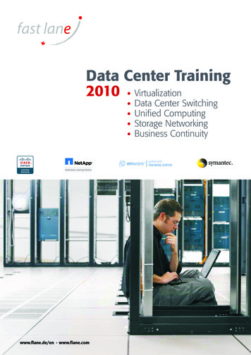
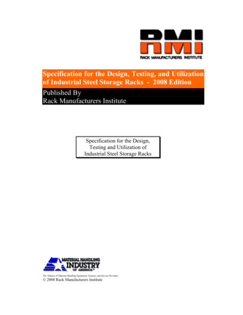
White PaperThe TIA/EIA-942 specification provides a simple reference for data center cabling that supportsdifferent cabling schemes, EoR or ToR, to meet differing needs from a physical and operationalperspective. The ToR model defines an architecture in which servers are connected to switchesthat are located within the same or adjacent racks, and in which these switches are connected toaggregation switches typically using horizontal fiber-optic cabling.ToR switching allows oversubscription to be handled at the rack level, with a small number of fibercables providing uniform connectivity to each rack. The advantage of this solution is that horizontalfiber can support different I/O connectivity options, including Gigabit Ethernet and 10 GigabitEthernet as well as Fibre Channel. The use of fiber from each rack also helps protect infrastructureinvestments as evolving standards, including 40 and 100 Gigabit Ethernet, are more likely to beimplemented using fiber before any other transmission mechanism. By limiting the use of copperto within racks, the ToR model isolates the cabling that changes most often to the parts of the datacenter that change most frequently: the racks themselves. The use of fiber runs from racksprovides a flexible data center cabling infrastructure that supports the transition from GigabitEthernet to 10 Gigabit Ethernet now, while enabling transition to 40 and 100 Gigabit Ethernet inthe future.Modular Data Center InfrastructureThe cabling and infrastructure design for a modern data center is governed by multiple factors.The TIA/EIA-942 Telecommunications Infrastructure Standard for Data Centers providesguidelines for data center cabling infrastructure that customers can adopt as a guide in the datacenter cabling and planning process. Other standards, such as BICSI, provide guidelines for datacenter cabling and implementation. The TIA/EIA-942 cabling specification considers the need forflexibility, scalability, reliability, and space management (http://www.tiaonline.org). While thestandard provides guidelines, specific design elements will vary with each data center. Generalconsiderations that apply to all data centers include: Support for storage devices (Fibre Channel, Small Computer System Interface [SCSI] orNAS, FCoE, etc.) Support for convergence and unified fabric with growth factors incorporated Reliability, scalability, and redundancy High-capacity and high-density server access requirements Flexibility and expandability with easy access for moves, additions, and changes Migration from Gigabit Ethernet to 10 Gigabit Ethernet server connectivity with futuresupport for 40 and 100 Gigabit Ethernet Cabling architecture balance with power, cooling, structural loading, management, andoperations needsIn the context of the TIA/EIA-942 simplified logical data center layout, the ToR architecture mapsdirectly to the EDA and the horizontal distribution area (HDA). Figure 1 shows a mapping of thelogical network architecture to the physical infrastructure.Figure 1.TIA/EIA-942 Logical Layout 2009 Cisco Systems, Inc. All rights reserved. This document is Cisco Public Information.Page 3 of 14
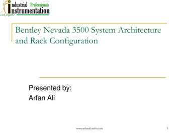
White PaperThe EDA in the TIA/EIA-942 logical layout corresponds to the area where server racks are placed.Traditional structured copper cabling with a mix of fiber if needed for SAN or high-speed serverconnectivity is used to connect the EDA to the HDA. The environment requires careful planning tohelp ensure that the structured cabling meets the initial design requirements with enough room forgrowth. In cases where server racks are not yet in place or without the physical infrastructureneeded to support rack-level flexibility, a zone distribution area (ZDA) cabling model is used. TheZDA allows for structured cabling to be placed under the floor or above the rack in anticipation offuture server racks requiring connectivity to the network equipment that may be housed in theHDA. The ZDA follows a structured cabling model to the HDA. The primary difference in thehorizontal cabling model between the ZDA and EDA is that the cables are terminated in the EDAracks, whereas the ZDA uses zone distribution blocks located outside the server racks.The ToR cabling and network architecture in Figure 1 optimizes the requirement for horizontalcabling from the server rack by placing the ToR aggregation device at the top of the server rack.Actual placement of the ToR device may vary based on customer requirements (for example, in orabove the server rack or ToR aggregation per two or three server racks) and seeks to optimizecustomer requirements for density, cabling, and design methodology. The aggregation of the ToRdevice will be in the HDA based on the specific TIA/EIA reference cabling model deployed. TheToR cabling design model follows a logical network layer construct in which the server networkconnectivity is aggregated at the rack level in the network access layer. The access layer is in turnconnected to the network aggregation layer.The ToR model uses fiber as the backbone cabling infrastructure that connects the EDA with theHDA and main distribution area (MDA). The ToR model augments the TIA/EIA-942 logicalapproach shown in Figure 1 by extending fiber as the backbone cabling of choice to the EDA orserver rack. The amount of fiber required will vary based on design requirements. For example, ina migration-type design in which a ToR model is used for Ethernet aggregation and Fibre Channelconnectivity is not unified I/O (UIO), additional fiber will be required for those servers requiring 2009 Cisco Systems, Inc. All rights reserved. This document is Cisco Public Information.Page 4 of 14
White PaperFibre Channel connectivity. In models in which UIO for Fibre Channel and Ethernet is assumed,the fiber requirement to the rack will be reduced. Other design augmentations, such as ToR for fewracks with inter-rack cabling, will modify the fiber requirements. These are a few examples of somedeployment models that have been adopted based on particular environment and requirements.The Pod ApproachThe easiest way to scale data center capacity is to use a highly modular architecture that enablesthe rapid deployment of infrastructure. One approach is to use a rack of servers as the basebuilding block, with ToR switches, and with all copper cabling contained within the rack.The TIA/EIA model provides a logical cabling layout that can be modularized for a data centerimplementation. When deploying large numbers of servers in the data center, it is extremelyimportant that the design footprint be scalable. One way to simplify the design and simultaneouslyincorporate a scalable layout is to divide the data center floor space into modular, easily duplicatedsubareas.This modular building block is used to design scalability into the network architecture at both OSILayers 1 and 2. This design assumes that all computer resources incorporate resilient network,power, and storage resources,
The data center’s access layer, or equipment distribution area (EDA), presents the biggest challenge to managers as they choose a cabling architecture to support data center computer connectivity needs. The ToR network architecture and cabling model proposes the use of fiber as the backbone cabling to the