Transcription
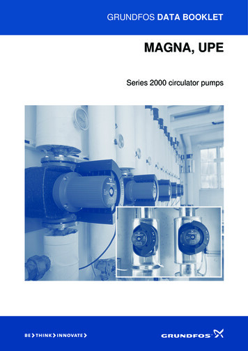
GRUNDFOS DATA BOOKLETMAGNA, UPESeries 2000 circulator pumps
ContentsProduct dataMAGNA/UPEDuty rangeCharacteristic featuresBenefitsApplicationsHeating systemsPumped liquidsType keyPerformance range, MAGNA (D), UPE(D)Installation333333344Product rangeProduct rangePump selectionPump sizeOperating conditionsCommunicationControl mode566666Operating conditionsOperating conditionsGeneral recommendationsLiquid temperatureAmbient conditionsMaximum operating pressureMinimum inlet pressureElectrical dataSound pressure level91010101111111111111212131314141515Curve conditionsCurve conditionsTechnical data23Base platesAdapter flangesCounter flanges for pumps with cast-ironpump housingCounter flanges for pumps with bronzepump housingBlanking flangesUnion and valve kitsUnion kitsValve kitsInsulation kitsExpansion modules for MAGNA25-60, 32-60, 25-100, 32-100,40-100(D), 50-100GENI moduleRelay moduleExpansion modules for MAGNA (D) 50-60,65-60, 32-120, 40-120, 50-120, 65-120GENI moduleLON moduleExpansion modules for single-phase UPEFault signal module MC 40/60Bus module MB 40/60R100PMU 2000PCU 2000G10-LON interfacePrefilter16161617MAGNA/UPE, cast ironMAGNA, stainless steelUPE, 57585858Further product documentationWebCAPSWinCAPS222Order dataConstructionMotor and electronic controllerPump connectionsSurface treatmentMaterial 88FunctionsFunctionsControl modes (factory setting)AUTOADAPTProportional-pressure controlAdditional control and operating modesConstant-pressure controlConstant-curve dutyMax. or min. curve dutyAutomatic night-time dutyAdditional operating modes of twin-head pumpsReadings and settings on the pumpCommunicationDigital inputDigital outputAnalog inputBus communication via GENIbusBus communication via LONFunctions of expansion modulesMechanical installationElectrical connectionCablesWiring diagram, single-phaseWiring diagram, three-phaseAdditional protectionSingle-phase MAGNASingle-phase UPEThree-phase UPE(D)Examples of connections5960
Product dataMAGNA, UPEMAGNA and UPEApplicationsThe MAGNA/UPE ranges of circulator pumps arespecially designed forHeating systems Main pump heating systems up to 2100 kW (Δt 20 C) and domestic hot-water systems (stainless-steel orbronze pump housing). Aicondition systems ( 2 C)up to 350 kW (Δt 6 C) (MAGNA only).MAGNAUPEMaximum flow, Q38 m3/h90 m3/h13 m10.5 mMaximum head, HMaximum system pressureLiquid temperature Heating surfaces.Aircondition surfaces (MAGNA only)The MAGNA/UPE circulator pumps are designed forcirculating liquids in heating systems with variable flowswhere it is desirable to optimise the setting of the pumpduty point. The pumps are also suitable for domestichot-water systems.Duty rangeData Mixing loops10 bar10 bar 2 C to 110 C 15 C to 110 CTo ensure correct operation, it is important that thesizing range of the system falls within the duty range ofthe pump.GR6460The MAGNA/UPE is especially suitable for installationin existing systems where the differential pressure ofthe pump is too high in periods with reduced flowdemand. The pump is also suitable for new systemswhere automatic adjustment of pump head to actualflow demand is required without using expensivebypass valves or the like.Furthermore, the pump is suitable for application insystems with hot-water priority as an external contactcan immediately force the pump to operate according tothe max. curve.Fig. 1 MAGNA/UPE pump rangesPumped liquidsCharacteristic features AUTOADAPT proportional-pressure duty constant-pressure duty constant-curve duty max. or min. curve duty parallel connection of pumps with PMU 2000 no external motor protection required.Benefits low noise level safe selection simple installation low energy consumption, all MAGNA pumps areenergy class "A" in addition to this, the AUTOADAPT function ensuresenergy savings for MAGNA pumps long life and no maintenance external control and monitoring enabled viaexpansion modules.Thin, clean, non-aggressive and non-explosive liquids,not containing any solid particles, fibres or mineral oil.If the pump is installed in a heating system, the watershould meet the requirements of accepted standardson water quality in heating systems, e.g. the Germanstandard VDI 2035.In domestic hot-water systems, the pump should beused only for water with a degree of hardness lowerthan approx. 14 dH. The pump must not be used forthe transfer of inflammable liquids such as diesel oiland petrol.If the pump is not used during periods of frost,necessary steps must be taken to prevent frost bursts.Additives with a density and/or kinematic viscosityhigher than those/ that of water will reduce the hydraulicperformance.Whether a pump is suitable for a particular liquid,depends on a number of factors of which the mostimportant are lime content, pH value, temperature andcontent of solvents, oils, etc.3
Product dataMAGNA, UPEType keyMAGNA (D), UPE(D)ExampleUPED80-120(F)(N)280Type rangeUPE(D):MAGNA (D):Electronic controlTwin-head pumpNominal diameter ofsuction and discharge ports (DN)Maximum head [dm]Flange connectionN: Single-head pump housing of stainless steelB: Single-head pump housing of bronzeA: Pump housing with air separatorPort-to-port [mm]Performance range, MAGNA (D) and UPE(D)p[kPa]H[m]1312M1065054042060MAGNA 25-1000-1)8E( DUP72070MAGNA (D) 32-12010-8)5(D80MAGNA (D) 40-120MAGNA 50-100MAGNA (D) 40-100MAGNA 32-10090NAAG100346810152030406080 100Q [m³/h]1234567 8 9 1020Q [l/s]Fig. 2 Performance range4TM03 1852 11060-60UPE(D) 10220(D) 65-11AMAGN1601060250-20(D )3D) 65NA (AGN-60320,05-62-4,3E2-40UP250,5-4E1UPMAGNA 25-6030MAGMAMAGNA 32-60
Product rangeMAGNA, UPEProduct rangePump typeSupply voltage1 x 230-240 V3 x 400-415 VPort-to-port length[mm]MAGNA 25-60z180MAGNA 32-60z180MAGNA 25-100z180Pipe connection1"1 1/2"2"Flange connectionPN 6/PN 10PN 6PN 10zzzMAGNA 32-100 (N)z180MAGNA 32-100 Fz220zzMAGNA (D) 40-100 Fz220zMAGNA 50-100 Fz240UPE 15-40z130UPE 25-40 (B)z180zUPE 25-40 Az180zUPE 32-40z180zzz130zUPE 25-60 (B)z180zUPE 25-60 Az180zUPE 32-60z180MAGNA (D) 32-120 F (N)z220zMAGNA (D) 40-120 F (N)z250zMAGNA (D) 50-60 F (N)z280zMAGNA (D) 65-60 F (N)z340zMAGNA (D) 50-120 F (N)z280zMAGNA (D) 65-120 F (N)z340zzUPE(D) 80-120 F (B)z360zzUPE(D) 100-60 F (B)z450zz5
Product rangeMAGNA, UPEPump selectionHeadDuty pointPump sizeSelection of pump size should be based on required maximum flow andOperating conditionsIt should be checked whether the operating conditionsare fulfilled, i.e.Flow liquid temperature and ambient conditions minimum inlet pressureTM02 2040 3301 maximum head loss in the system.Fig. 3 Performance curve maximum operating pressure.BMSCommunicationThe requirements for external control or monitoring ofthe pump should be considered, such as access toPMUPCU speed control of pump or change of setpoint start/stop, fault indication or forced control tomax. or min. curve.Note: The communication options depend on the pumptype.MAGNA/UPEControl modeIn general, Grundfos recommends the factory setting which is suitable for mostinstallations proportional-pressure control in systems withrelatively great head losses constant-pressure control in systems with relativelysmall head losses.6UPE/MAGNA/TPEFig. 4 Building management system with four pumpsin parallel controlled via a PMU 2000 anda PCU 2000TM02 2044 3301 reading of pump data
Operating conditionsOperating conditionsMAGNA, UPEMaximum operating pressure10 bar.General recommendationsMinimum inlet pressureMAGNA/UPEWater in heatingsystemsWater quality according to local standardssuch as the German standard VDI 2035Domestic hot waterDegree of hardness up to 14 dHThe following relative minimum pressures must beavailable at the pump inlet during operation:Liquid temperatureWater containing glycol Viscosity 10 mm2/sPump typeLiquid temperatureApplicationGeneralDomestic hotwater systemsTimeShort periods75 C90 C95 CInlet pressure [bar]MAGNAUPEMAGNA 25-60, 25-100, 32-60, 32-100,40-100(D), 50-1000.1–0.35 110 C 110 CUPE 15-40, 25-40, 25-60, 32-60, 32-400.050.28–MAGNA (D) 32-120 FMAGNA (D) 40-120 FMAGNA (D) 50-60 F0.150.45–MAGNA (D) 50-120 F0.400.70–MAGNA (D) 65-60 F0.150.45–MAGNA (D) 65-120 F0.901.20–UPE(D) 80-120 F1.601.90–UPE(D) 100-60 F0.951.25–Continuously 2 C to 95 C 15 C to 95 CContinuously 2 C to 60 C 15 C to 60 CTo avoid condensation in the terminal box and thestator, the liquid temperature must always be higherthan the ambient temperature.Ambient conditionsAmbient temperatureduring operation:0 C to 40 CAmbient temperatureduring storage/transport:–40 C to 60 CRelative air humidity:Maximum 95 %.Note: Actual inlet pressure pump pressure against aclosed valve must be lower than the maximumpermissible system pressure.7
Operating conditionsMAGNA, UPEElectrical dataMAGNA/UPEPump typeSingle-phase MAGNA25-60, 25-100, 32-60,32-100, 40-100(D), 50-100Single-phase MAGNA (D)32-120, 40-120, 50-60,50-120, 65-60, 65-120Enclosure classIP 44 (IEC 85)IP 44 (IEC 85)IP 42IP 42Insulation classFFHHExternal start/stopinputExternal potential-freeswitch. Screened cable.Maximum contact load:5 V, 10 mA.External potential-free switch. MC 40/60 Screened cable.MB 40/60 Maximum contact load:5 V, 10 mA.External potential-free switch.Screened cable.Maximum contact load:5 V, 2.7 mA.GENI module GENI module Max. and min. curve inputExternal potential-free switch.Screened cable.Maximum contact load:5 V, 2.7 mA. Input for analog 0-10 VsignalExternal signal: 0-10 VDC.Maximum contact load: 1 mA.Internal potential-freechangeover contact. Screened cable.Maximum contact load:250 VAC, 2 A.Minimum contact load:5 VDC, 1 mA.Internal potential-freechangeover contact.Screened cable.Maximum contact load:250 VAC, 2 A.Minimum contact load:5 VDC, 1 mA.GENI module LON module Bus inputGENI module LON via GENIbus andG10 modulesSupply voltage1 x 230-240 V – 10 %/ 6 %, 1 x 230-240 V – 10 %/ 6 %, 1 x 230-240 V – 10 %/ 6 %, 3 x 400-415 V 10 %, 50 Hz, PE50/60 Hz, PE50/60 Hz, PE50 Hz, PESingle-phaseUPEMC 40/60 MB 40/60 Setpoint signalsSignal outputMC 40/60 MB 40/60 Three-phaseUPE(D)Internal potential-free changeover contact.Screened cable.Maximum contact load:250 VAC, 2 A.Minimum contact load:5 VDC, 1 mA.Grundfos GENIbus protocol.Screened cable.Lead cross section:0.25 - 1 mm2.Maximum cable length: 1200 m.The pump requires no external motor protection.Earth leakage currentIleak 3.5 mAThe leakage currents are measured in accordance with EN 60355-1.EMCEN 61800-3. Expansion moduleSound pressure level8Pump typeSingle-phase MAGNA25-60, 25-100, 32-60,32-100, 40-100(D), 50-100Single-phase MAGNA (D)32-120, 40-120, 50-60,50-120, 65-60, 65-120Single-phaseUPEThree-phaseUPE(D)Sound pressure level 54 dB(A) 54 dB(A) 43 dB(A) 54 dB(A)
FunctionsMAGNA, UPEFunctionsSingle-phase MAGNA25-60, 25-100, 32-60,32-100, 40-100(D), 50-100Single-phase MAGNA (D)32-120, 40-120, 50-60,50-120, 65-60, 65-120zzSingle-phaseUPEThree-phaseUPE(D)zzControl modes (factory setting)AUTOADAPT Proportional-pressure controlAdditional control and operating modesProportional-pressure controlzzzzConstant-pressure controlzzzzConstant-curve dutyzzzzMax. or min. curve dutyzz zAutomatic night-time dutyzzAlternating operation zzzStandby operationzzzOperating indicationzzFlow indicationzzSetpointzControl modezFault indicationzAdditional operating modes of twin-head pumpsReadings and settings on the pumpzzzzzzzzzzzCommunicationWireless remote control, R100zzzzExternal digital input/output zExternal analog input zBus via GENIbus protocol, RS-485 zBus via LonTalk protocol, FTT 10 z Function incorporated.Expansion module required.G10-LON interface required.Not recommended for aircondition systems.9
FunctionsMAGNA, UPEControl modes (factory setting)HThe pumps have been factory-set toHmax. AUTOADAPT (MAGNA). proportional-pressure control (UPE).The factory setting is suitable for most installations.Hset1Hfac.A1Hauto minAUTOADAPTDuring operation, the pump automatically reduces thefactory-set setpoint and adjusts it to the actual systemcharacteristic.Hset2A3A2QTM03 1071 4005The setpoint is factory-set to half of the maximum pumphead.Fig. 6 AUTOADAPTProportional-pressure controlThe pump head is changed continuously in accordancewith the flow demand in the system.HThe head against a closed valve is half the setpoint.00QFig. 5 AUTOADAPT controlHsetHset2Note: Manual setting of the setpoint is not possible.When the control mode AUTOADAPT has beenactivated, the pump will start at Hset1, corresponding to50 % of its maximum head, and then adjust itsperformance to A1, see fig. 6.When the pump registers a lower pressure on the max.curve, A2, the AUTOADAPT function automaticallyselects a correspondingly lower control curve, Hset2.If the radiator valves close, the pump adjusts itsperformance to A3.A1:Original duty point.A2:Lower registered pressure on themax. curve.A3:New duty point after AUTOADAPT control.Hset1:Original setpoint setting.Hset2:New setpoint after AUTOADAPT control.Hfac.:MAGNA xx-60: 3.5 m.MAGNA xx-100: 5.5 m.Hauto min: A fixed value of 1.5 m.The AUTOADAPT control mode is a form of proportionalpressure control where the control curves have a fixedorigin, Hauto min.The AUTOADAPT control mode is developed specificlyfor heating applications and not recommended for aircondition systems.10QTM00 4488 09951.5TM02 0826 0904HFig. 7 Proportional-pressure controlThe proportional-pressure control is recommended insystems with relatively great head losses.
FunctionsMAGNA, UPEAdditional control and operatingmodesMax. or min. curve dutyThe pump can be set to operate according to the max.or min. curve, like an uncontrolled pump.HThe functions available depend on the pump type andthe expansion module chosen, see overview offunctions on page 9.Max.Constant-pressure controlMin.The pump head is kept constant, independent of thewater requirement.QTM00 5547 4596Grundfos offers additional control and operating modesto meet specific demands.Fig. 10 Max. or min. curvesHThe max. curve mode can be used in periods in whicha maximum flow is required. This operating mode is forinstance suitable for hot-water priority.QTM00 4489 0995HsetThe min. curve mode can be used in periods in whicha minimum flow is required. This operating mode is forinstance suitable for manual night-time duty.Automatic night-time dutyWhen automatic night-time duty has been selected, thepump will change automatically between normal dutyand night-time duty. Changeover between normal dutyand night-time duty takes place as a result of the flowpipe temperature measured by an integratedtemperature sensor.Fig. 8 Constant-pressure controlThe constant-pressure control is recommended insystems with relatively small head losses.Constant-curve dutyRequires the use of an R100 remote control.The pump can be set to operate according to a constantcurve like an uncontrolled pump.If an external controller is installed, the pump is able tochange from one constant curve to another, dependingon the value of the external signal.The automatic changeover to night-time duty takesplace when the temperature sensor registers a flowpipe temperature drop of more than 10-15 C withinapprox. 2 hours. The required temperature drop is aminimum of 0.1 C/min.Changeover to normal duty takes place without a timelag when the temperature has increased by approx.10 C.HAdditional operating modes of twin-headpumpsMin.Fig. 9 Constant-curve dutyQTM03 0551 0205Max.The following operating modes are available for twinhead pumps:Alternating operationPump operation alternates every 24 hours. If the dutypump stops due to a fault, the other pump will start.Standby operationOne pump is operating continuously. In order to preventseizing-up, the other pump will start at a fixed frequency(every 24 hours) and run for a short period. If the dutypump stops due to a fault, the other pump will start.11
FunctionsMAGNA, UPEReadings and settings on the pumpCommunicationThe control panel on the pump control box/terminal boxincorporates the basic functions for readings andsettings.Depending on pump type, MAGNA/UPE enablescommunication via wireless remote control, R100 connection to an external alarm device digital input/outputMA51X analog input.STOPm3/h100%TM00 4498 2802EXTAUTOADAPT34TM03 0379 50042Fig. 11 MAGNA control panelPos.Fig. 13 R100 remote controlMAGNA/UPE is designed for wireless communicationwith the Grundfos R100 remote control.The R100 offers additional possibilities of setting andstatus displays for the pump.Description1Buttons for setting of headThe R100 can be used for the following functions:2 Indicator lights for operating and fault indication and symbol for indication of external control reading of operating data reading of fault indications3Button for selection of control mode:AUTOADAPT, proportional pressure, constant pressure andautomatic night-time duty4Light symbols for indication of control mode and night-timeduty setting of 0.1 m head increments5Light fields for indication of head, flow and operating mode setting of control mode selection of external setpoint signal allocation of pump number making it possible todistinguish between pumps in connection withparallel operation via bus1 selection of function for digital input.The MAGNA/UPE has various inputs and outputs forexternal signals for forced-control functions. Somefunctions may require an expansion module.3TM00 4431 06032Grundfos GENIbusFig. 12 UPE control panel1DescriptionButtons for start/stop of the pump, setting of setpoint, controlmode, min. and max. curve2Light fields for indication of control mode and setpoint3Indicator lights for operating and fault indicationTM03 3040 0106Pos.Fig. 14 MAGNA with expansion module12
FunctionsMAGNA, UPEDigital inputDigital outputExternal start/stopThe pump can be started or stopped via the digitalinput.The pump incorporates a signal relay with a potentialfree changeover contact for external fault indication.Start/stopMAGNA 25-60, 25-100, 32-60, 32-100, 40-100, 50-100The function of the signal relay can be changed from"Fault" to "Operating" or "Ready" mode with the R100.HNormal dutyThese pumps require expansion modules.The functions of the signal relay are as shown in thetable below:QHStopSignal relay Fault signalQ1 23NC NO CExternal forced max. or min curveThe pump can be forced to operate on the max. or mincurve via the digital input.1 2 3NC NO C1 2 3NC NO CMax. curveNot activated: The electricity supply has been switched off. The pump has not registered a fault.Activated: The pump has registered a fault.Signal relay Operating signalHNormal duty1 23NC NO C1 2 3NC NO CQHMax. curveQ1 2 3NC NO CNot activated: The pump has been set to stop. The pump has registered a fault and is unable torun.Activated: The pump is running. The pump has registered a fault, but is able to run.Signal relay Ready signalMin. curve1 23NC NO C1 2 3NC NO CHNot activated: The pump has been set to stop. The pump has registered a fault and is unable torun.Normal dutyQ1 2 3NC NO CHMin. curveQThe function of the digital input is selected with theR100 remote control.Activated: The pump is ready to run or is running.MAGNA 32-120, 40-120, 50-60, 50-120, 65-60, 65-120The function of the signal relay can be changed from"Fault" to "Operating" mode with the R100.The functions of the signal relay are as shown in thetable below:Signal relay Fault signal1 23NC NO C1 2 3NC NO C1 2 3NC NO CNot activated: The electricity supply has been switched off. The pump has not registered a fault.Activated: The pump has registered a fault.Signal relay Operating signal1 23NC NO C1 2 3NC NO C1 2 3NC NO CNot activated: The pump has been set to stop. The pump has registered a fault and is unable torun.Activated: The pump is running. The pump has registered a fault, but is able to run.13
FunctionsMAGNA, UPEAnalog inputBus communication via GENIbusThe bus enables control and monitoring of the pumpsfrom a GRUNDFOS Pump Management System 2000,to a building management system (BMS) or anotherexternal control system.External analog controlRequires an expansion module.Control of setpoint or speed via an external 0-10 Vsignal.Max. curve12345678910U VMAGNA/UPEFig. 15 Example of 0-10 V controlThe analog input enables the following control modes:In constant-curve mode, the pump is able to changefrom one constant curve to another depending on thevalue of the external signal.The internal controller is inactive in this mode.TM03 2394 4005Min. curve0TM00 5550 0904Setpoint/constant curveH mFig. 16 Example of single-pump operationPump typeRequiresMAGNAGENI moduleUPE, single-phaseMB 40/60 moduleUPE, three-phase–See sectionAccessories–In pressure control mode, the setpoint can be setexternally within the range from the setpoint to the min.curve.BMSThe internal controller is active in this mode.TM03 2395 4005At an input voltage lower than 0.5 V, the pump willoperate according to the min. curve.MAGNA/UPEFig. 17 Example of pumps operating in parallel14Pump typeRequiresMAGNA GENI module PMU 2000 or PCU 2000UPE, single-phase MB 40/60 module PMU 2000 or PCU 2000UPE, three-phase PMU 2000 or PCU 2000See sectionAccessories
FunctionsMAGNA, UPEBus communication via LONPump typeVia the bus input, the pump can be connected to anetwork based on LonWorks technology, and thus belinked to other units based on this communicationstandard.BMSGENI module LON moduleMAGNA25-60, 32-60, 25-100,32-100, 40-100(D),50-100MAGNA (D)50-60, 65-60, 32-120,40-120, 50-120,65-120G10-LONzzzUPE, single-phasezUPE, three-phasezG10-LONTM03 3041 0106ExpansionmoduleFig. 18 Example of single-pump operationFunctions of expansion modulesPump typeMAGNA25-60, 25-100, 32-60,32-100, 40-100, 50-100MAGNA (D)32-120, 40-120, 50-60,50-120, 65-60, 65-120UPE, single-phaseInputs/outputs incorporatedWith expansion moduleFunctionRelay moduleStart/stopSignal relayGENI moduleStart/stopMax. curveMin. curve0-10 V analog inputTwin-head pump controlGENIbusSignal relayGENI moduleMax. curveMin. curve0-10 V analog indputTwin-head pump controlGENIbusLON moduleLonTalk protocol, FTT10MC 40/60Start/stopMax. curveMin. curve0-10 V analog inputMB 40/60Start/stopMax. curveMin. curve–Start/stopSignal relay–15
ConstructionThe MAGNA/UPE is of the canned-rotor type, i.e. pumpand motor form an integral unit without shaft seal andwith only two gaskets for sealing. The bearings arelubricated by the pumped liquid.The pump is characterised by controller integrated in the terminal box control panel on the terminal box terminal box prepared for optional modules differential-pressure and temperature detection cast-iron, stainless-steel or bronze or pump housing twin-head versions air separator pump housing, types UPE 25-40 A andUPE 25-60 A no external motor protection required.Motor and electronic controllerThe single-phase MAGNA motor is a 4- or 8-pole,synchronous, permanent-magnet motor (PM motor).This motor type is characterised by higher efficiencythan a conventional asynchronous squirrel-cage motor.Pump speed is controlled by an integrated frequencyconverter.The single-phase UPE motor is a 2-pole,asynchronous squirrel-cage motor with radio noise filterto VDE 0875. The terminal box and the motor-pumpunit have been tested in accordance with VDE 0700.The terminal box incorporates a controller. The pumpspeed is calculated via a built-in induction coil on thestator winding.The three-phase UPE motor is a 2-pole, asynchronoussquirrel-cage motor with integrated frequencyconverter.A differential-pressure and temperature sensor formsan integral unit. The sensor is located inside the pumphousing in a channel between suction and dischargesides. Twin-head pumps have two sensors.Pump connectionsThreaded pump connections to ISO 228/1.Flange dimensions to ISO 7005-2/BS4504.Surface treatmentThe pumps are wet-varnished.Colour: NCS40-50R.16MAGNA, UPE
ConstructionMAGNA, UPEMaterial specification1MAGNA/UPEComponentMaterial1Terminal boxAluminium/composite2Stator housingAluminium AlSi 10Cu2O-ringsEPDM rubberOuter bearing ringAluminium oxide Al2O3Rotor canStainless steel4ShaftStainless steel ortungsten carbide oraluminium oxide5Thrust bearingCarbon MY 106Bearing plateStainless steelInner bearing ringAluminium oxide Al2O3orsilicium carbide SiOImpellerStainless steel orcomposite8Pump housingCast ironEN-GJL150/-200/-250,bronze or stainlesssteel9Differential-pressureand temperature sensorComposite PES367EN/DIN1.4301 or1.4401TM02 1256 0801Pos.1.43012345678Fig. 20 MAGNA 32-120, 40-120, 50-60, 50-120, 65-60and 65-120146TM02 1257 380178235Fig. 21 UPE 15-40, 25-40, 32-40, 25-60 and 32-60TM03 1955 3405189Fig. 19 MAGNA 25-60, 25-100, 32-60, 32-100, 40-1007and 50-1002356TM02 1258 06034Fig. 22 UPE 80-120 and 100-6017
InstallationMechanical installationElectrical connectionMAGNA/UPE is for indoor installation. The pump mustbe installed with horizontal motor shaft.The electrical connection and protection should becarried out in accordance with local regulations.The pump may be installed in horizontal as well asvertical pipes. The pump must be connected to an external mainsswitch.Arrows on the pump housing indicate the liquid flowdirection through the pump. The liquid flow directioncan be horizontal or vertical, depending on the terminalbox position. The pump must always be correctly earthed.The terminal box can be turned to various positions,depending on pump type. This is described in theinstallation and operating instructions.The pump must be installed in such a way that strainfrom the pipework is not transferred to the pumphousing.The pump may be suspended direct in the pipes,provided the pipework can support the pump. If not, thepump must be installed on a mounting bracket or baseplate.To ensure cooling of motor and electronics, thefollowing must be observed: Place the pump in such a way that sufficient coolingis ensured. The temperature of the cooling air must not exceed40 C.18MAGNA, UPE The pump requires no external motor protection.The motor incorporates thermal protection againstslow overloading and blocking (IEC 34-11: TP 211). When the pump is switched on via the mains, thepump will start after approx. 5 seconds.Note: The number of starts and stops via the mainssupply must not exceed 4 times per hour.The pump mains connection must be made as shown inthe diagrams on the following pages.CablesUse screened cables (0.25-1.5 mm2) for external on/offswitch, digital input, sensor and setpoint signals. All cables used must be heat-resistant up to at least 85 C. All cables used must be installed in accordance withEN 60204-1.
InstallationMAGNA, UPEWiring diagram, single-phaseExternal switchELCBTM03 2397 4005Max. 10 A/16 AFig. 23 1 x 230-240 V –10 %/ 6 %, 50/60 HzWiring diagram, three-phaseExternal switchMax. 16 AL1ELCBL3PEL2L3TM00 9270 4696L2L1Fig. 24 3 x 400-415 V 10 %, 50/60 HzAdditional protectionIf the pump is connected to an electric installationwhere an earth-leakage circuit breaker (ELCB) is usedas an additional protection, the earth-leakage circuitbreaker must be marked with the following symbols.Single-phaseThe earth-leakage circuit breaker must trip out whenearth fault currents with DC content (pulsating DC)occur.Three-phaseThe earth-leakage circuit breaker must trip out whenearth fault currents with DC content (pulsating DC) andsmooth DC earth fault currents occur.19
InstallationMAGNA, UPESingle-phase MAGNASingle-phase UPENTM03 0902 070512TM00 4449 3399TM03 0899 0705LFig. 27 Single-phase UPE mains connectionThree-phase UPE(D)SignaloutputDifferentialpressure andtemperaturesensorMainsconnectionTM03 0520 01051 2 33NCNO CL3 L2 L1Fig. 25 MAGNA 25-60, 25-100, 32-60, 32-100,40-100(D), 50-100, mains connection withAlpha power plugStart/stopMin. curve(night-time duty)Max. curveAnalog 0-10 VinputDC 0-10 VMainsconnectionTM00 9120 33014 5 6 7 8 9 10 11 12A Y BFig. 28 Three-phase UPE(D) mains connectionSignal outputStart/stopSingle-head pumps are connected as shown above.1 2 3L NSTOPNC NO CPotential-free relay inputTM02 0235 10078 7Fig. 26 MAGNA 32-120, 40-120, 50-120, 65-120, 50-60,65-60, mains connectionNote: If no external on/off switch is connected, theconnection across terminals STOP and should bemaintained. If no external on/off switch is connected, theconnection across terminals 7 and 8 should bemaintained. If the 0-10 V input is used (terminals 11 and 12),there must be a connection across terminals7 and 9 (input for min. curve must be closed).Twin-head pumpsBoth pumps must be connected to the mains. A possible external controller is to be connected tothe master pump (terminals 7 to 12). If the twin-head pump is to be connected to aPMU 2000 or PCU 2000, it must be set to singlepump operation.The bus connection between master and slavepumps can be removed. Both master and slavepumps must be connected to the bus system.20
InstallationMAGNA, UPEExamples of connectionsConnection to external controllersL NSTOPNC NO C1 2 38 7Mains connectionOperationAlarmStartDry-running protectionTM02 1322 3601StopFig. 29 Example of MAGNA pumpConnection to external controllers1 2 38 74 5 6 7 9 10 11 12 21 22 2310 VA Y BMINNC NO CMAXL NSTOPX Q ZGENIbus10 VMINMAXSTOPAlarmMains connectionSetpoint settingDC 0-10 VStartFrost protectionTM02 1323 5101StopFig. 30 Example of MAGNA pump with GENI module21
Curve conditionsCurve conditionsThe guidelines below apply to the performance curveson pages 23 to 50: The bold parts of the curves show therecommended performance range. Test liquid: Airless water. All curves show average values and should not beused as guarantee curves. If a stated minimumperformance is required, individual measurementsmust be made. MAGNA (D) and UPE(D) have been tested at 60 C.The conversion between head H [m] and pressure[kPa] has been made for water at 60 C(ρ 983.2 kg/m3). For liquids with other densities,e.g. hot water, the d
Expansion modules for MAGNA (D) 50-60, 65-60, 32-120, 40-120, 50-120, 65-120 55 GENI module 55 LON module 55 Expansion modules for single-phase UPE 56 Fault signal module MC 40/60 56 Bus module MB 40/60 56 R100 57 PMU 2000 57 PCU 2000 57 G10-LON interface 57 Prefilter 57 Order data MAGNA/UPE, cast iron 58 MAGNA, stainless steel 58 UPE, bronze 58

![How to choose a broker [EN] - Forex Tester](/img/51/how-to-choose-a-broker.jpg)