Transcription
Slot MachineFinal Project ReportDec. 14, 2002E155Jason Quach and Daniel SutoyoABSTRACT:Over the years, slot machines have evolved from its mechanical roots and now arecompletely run by electronic systems. In light of this paradigm shift in operations, theobjective of this project is to design and implement a slot machine that is run by theFPGA and HC11. The project incorporates 3 stepper motors, 3 reels (with eight iconson each reel), a keypad, two seven segment displays, wooden supports, along with theFPGA and HC11 in the creation of the slot machine. The main problem associatedwith this project is determining where the reels need to spin in each game and how toget them there with consistency. The result of the project is a working slot machinethat is very fun to play.1
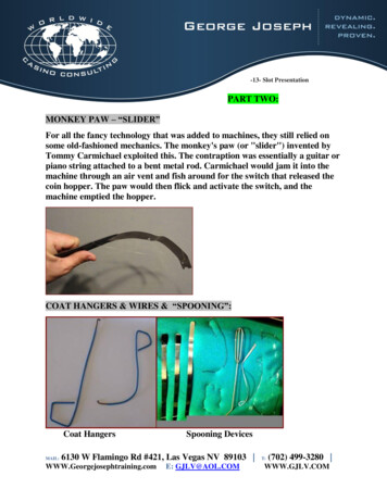
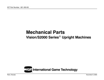
1.INTRODUCTION1.1.BACKGROUNDSlot machines, unlike traditional table games, require no gambling knowledge. Itssimplicity has brought it unparalleled success as the most popular and profitable game incasinos worldwide. Although modern versions of slot machines retain the old classic view, ithas steadily evolved over the years and now is run by an electronic system rather than amechanical system. Thus, modern slot machines may look like the old ones, but they are runon an entirely different principle. The outcome of each game is actually determined by thecentral computer inside the machine, not the motion of the reels.The slot machine created in this project is quite similar to that of a modern slotmachine. The project consists of three stepper motors, three reels (each with eight icons),wooden supports for the reels, a 4x4 keypad using three buttons (spin, increase bet, anddecrease bet), two dual seven segment displays which show the remaining credits and theamount of credits being bet, and a LED that lights up when the player hits the jackpot. Whenthe user presses start, the amount bet is deducted and the reels all begin to spin. The first reelmakes about ten full revolutions before stopping, while the second reel makes about twelve,and the third makes about fifteen. There are three spinning speeds for the reels: slow (810rad/s), medium (1014 rad/s), and fast (1206 rad/s). The reels initially start out at mediumspeed, increase to fast speed, and finally revert to slow speed as they near their destination. Iftwo or three icons match, the player is rewarded accordingly.1.2.MOTIVATIONThe motivation for creating a slot machine deals with the shift from mechanical toelectrical systems in recent years. With modern slot machines being controlled by electricalsystems rather than mechanical systems, it is feasible and desirable to create such a devicewith the tools at our disposal.1.3.BLOCK DIAGRAMThe following picture is the block diagram of the slot machine. There are five majormodules that are used in the implementation of the slot machine: the keypad, random numbergenerator, motor, encoder, and credits module. The keypad module controls the buttonpresses. The random number generator module does what its name suggests and generatespseudo random bit sequences using LFSR (linear feedback shift registers). The encodermodule takes as inputs the random numbers and encodes it into the corresponding icons thatwill be displayed. The motor module’s function is to spin the reels to the correct location.Finally, the credits module keeps tracks of the remaining credits, bets, and winnings.2
Figure 1: Overall Block Digram1.4.PARTITIONS OF THE OVERALL SYSTEM1.4.1. FPGAAt the heart of any modern slot machine is a random number generator, which ensuresthat each game has an equal chance of hitting the jackpot. The FPGA acts as the centralcomputer of the slot machine and performs three important functions: generating randomnumbers, controlling the movement of the reels, and keeping track of the number of credits.When the user presses the start button, the FPGA automatically deducts the amount of creditsbeing bet and also obtains three random numbers which will be used to determine the next setof symbols that will appear on the reel. Using this information, the FPGA sends thenecessary information that will drive the stepper motors to the correct location. After thereels stop spinning, the FPGA determines if there is a win or not and rewards the amount ofcredits won; in the case of a jackpot, an LED lights up.3
1.4.2. HC11The microcontroller is used to control the spinning speed of the reels. For thepurposes of this project, the microcontroller is used to generate a square wave that exhibits adifferent frequency for three intervals. The first interval of the square wave has a frequencyof 323 Hz, the second has a frequency of 384 Hz, and the final interval has a frequency of258 Hz. When the start button is pressed, the EVB (polling for this signal) generates a squarewave with 323 Hz for about 1 second, then changes to 384 Hz for about 1.2 second, andfinally adjusts to 258 Hz until all the motors stop spinning. Once this happens, the EVBreverts to outputting a square wave of 323 Hz until another game is started, which causes theEVB to repeat the same set of instructions. The square wave signal outputted from the EVBis sent to the motor module, which is responsible for generating the pulses which run thestepper motors.2.NEW HARDWARE2.1.STEPPER MOTORThe Airpax unipolar stepper motor is an inexpensive device ( 1.95) that offers greatprecision and control. It has high torque, step angles of 7.5 degrees, the ability to spin eitherclockwise or counterclockwise, in addition to supporting a wide variety of supply voltages.Also, the rotation speed of a stepper motor is independent of load, provided it has sufficienttorque to overcome slipping.In this project, stepper motors are used to move the reels to their correct location. Theteam decided to use plastic reels due to its relatively light weight. This would prevent themotors from slipping from insufficient torque. The team connected circular metal plates witha tiny hole in the center to the metal shaft of the stepper motor. The metal plate was superglued to the shaft and acted as a platform to which the reels could be attached. As can beseen, slot machines require consistent and accurate positioning of the reels and steppermotors fulfill both of these requirements nicely.A unipolar stepper motor is made up of two coils and has 5, 6, or 8 leads. The steppermotors that the team worked with had 6 leads, consisting of: ground, power, and the 4 phasesignals that control the two coils of the motors. To drive these motors, the team utilized amotor driver chip and an H bridge to facilitate its operation. More specifically, the team usedthe EDE1200 chip to translate a pulse into the 4 phase signals needed to drive the motor andthe L293D to amplify the current of these 4 phase signals.2.2.EDE1200 MOTOR DRIVER CHIPThe EDE1200 unipolar stepper motor driver chip is a 5 volt 18 pin device thatprovides control over 5/6 leads stepper motors. Its two main capabilities are driving motors instand alone “run” mode or external pulse drive “step” mode. In run mode, the stepper motorsfreely spin based on the predetermined pin settings. In step mode, the stepper motor takes astep on every falling edge of a pulse. Other features in the motor driver chip include halfstepping, direction, and speed control (only in “run” mode). Inputs to the EDE1200 arepower, ground, oscillator connection, and an external pulse if the chip is set to “step” mode.4
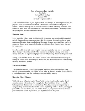
The main reason the EDE1200 was chosen is because of the simplicity of outputtingstepper motor phase sequences through the input of a single pulse. Other reasons includedthe variety of stepper motor behavior controls. Instead of creating logic to output alternatingphase sequences to the 4 leads of the stepper motor, one only needs to output a pulse to theEDE1200. At the falling edge of the pulse, the EDE1200 will generate the phase signals foreach of the 4 leads which will drive the motor.The FPGA outputs the correct number ofdigital pulses (which corresponds to thenumber of motor steps) to the pin 9 of theEDE1200 chip. The pin connections forthe EDE1200 are: P3, P4, P6, P7, P8, P10,P14 to 5V DC, P5, P11, P12, P13 toground, and P15, P16 to the FPGA masterclock signal (1 MHz). The digital pulseemitted from the FPGA is sent to P9 ofthe EDE1200. This will generate outputdrive signals P1, P2, P17, P18 (each ofwhich have a 40mA maximum rating) forthe four coils of a stepper motor. Referto the bread board schematic to see howthe chip is hooked up.Figure 2: EDE1200 Motor Driver Pin DiagramIn order to ensure that the stepper motor is configured correctly, the team first testedthe stepper motor in its “run” mode (P10 on ground) to make sure that it would freely spin.Once the team got the motor working in this mode, the team went on to test it in “step” mode.To test that the motor works in step mode, a square wave signal from the Agilent WavetekGenerator was applied to P9 of the EDE1200 chip. An observation that was made is that theEDE1200 speed control pins only apply in RUN mode. In step mode, the frequency of thesquare wave applied to P9 and the speed of the stepper motor are directly related.For references on other key features and specifications of the EDE1200, please referto http://www.componentkits.com/dslibrary/EDE1200.pdf (trouble shooting document) orhttp://www.elabinc.com/1200 faq.pdf (provides answers to several frequently askedquestions).2.3.L293D H-BRIDGEBecause the stepper motors require more current to operate than the EDE1200 canoutput, the team utilized the L293D to remedy this problem. The L293D integrated circuit isa very common motor driver chip thatprovides up to 600mA, which is more thanenough current to sufficiently drive thestepper motors. The inputs to the L293D arepower, ground, and the four phase drivesignals.5
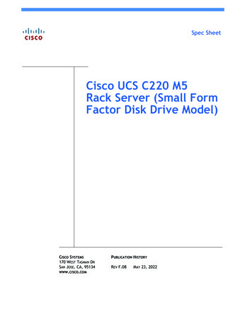
The pin connections for the L293D are: P1, P8, P9, P16 to 5V DC, P4, P5, P12, P13 toground, and P2, P7, P10, P15 receiving the corresponding EDE1200 drive signals. Then theL293D pins P3, P6, P11, P14 will deliver the same EDE1200 output signals but with muchmore current. The six lead stepper motor is connected in the following manner: red to 5VDC, orange to P2, yellow to P7, brown to P11, green to P14, and black unconnected (refer tofigure 4).3.SCHEMATICSFigure 3: L293D Motor Drive Pin DiagramFigure 4: EDE1200 and L293D Hookup Diagram6
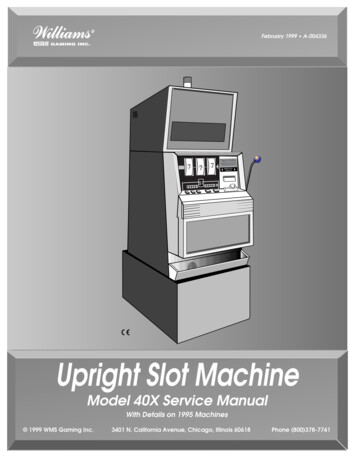
FPGA I / O PinsInput PinsP10, P45, P47-49, P81,Vdd, ground (not shown)Output PinsP7-9, P13-14, P18, P23- 29, P46, P50-51, P61-62,P65-69, P82-83EVB I / O PinsInput PinsPortC[3:0]Output PinsPortB[0]NoteThe three blocks with Step, Osc 1 &2, and OUT 1-4 are the overall blockfor the EDE1200 and L293D hook updiagram from figure 4.OrangeYellowGreenBrownRedFigure 5: Bread Board Circuitry7
4.FPGAThe FPGA takes in as inputs the EVB generated square wave and the user keypresses. It outputs the credits and bet display, pulses that will be used to run the steppermotors, and a signal that informs the EVB when to start its instruction. The followingdescriptions are of the key modules involved in the implementation of the slot machine.4.1.KEYPAD, CREDITS DISPLAY, AND BET DISPLAYThe keypad decoder module polls a 4x4 matrix keypad for input. The slot machineuses three input keys: spin, up, and down. The amount bet is controlled by the up and downbuttons, ranges from 1 to 3, and is displayed on a dual seven segment display. The creditsremaining are shown on a separate dual seven segment display and is initially set to 40.When the spin button is pressed, the credits remaining decreases based on the amount ofcredits bet. Once the player reaches zero, the game will not start until it is reset.In our design, the number of credits available range from 0-99 and is represented inthe verilog code as 8 bits. The 4 most significant bits are used to represent the ten’s placeand the 4 least significant bits are used to represent the one’s place. In the verilog code, theten’s place is designated as “dig1” and the ones place designated as “dig0.” This is donebecause the seven-segment decoder is limited to decoding single digit values. By splitting upthe credits into two separate numbers, it will be easier to decode and display them. For moreinformation, refer to appendix A – module 20.4.2.RANDOM NUMBER GENERATORThe random number generator used in this slot machine is emulated by the FPGAthrough the use of LFSR. Our design constantly generates three random numbers that rangefrom 0 to 63. This is accomplished by using three different lengths of LFSR (6, 7 and 8 bit).Three random numbers are acquired directly from the three LFSR when the player pressesspin.4.3.ICON ENCODERThe encoder takes in, as inputs, each of the three random numbers. It outputs thecurrent set of symbols and the next set of symbols. When the FPGA is turned on or when itis reset, the current set of symbols is defaulted to the watermelon icons. However, the reelpositions will have to be manually reset because the FPGA has no memory of the previousposition of the reels. On the rising edge of spin, three random numbers are sent to theencoder. At this point, the current set of symbols gets the values of the next set of symbolswhile the next set of symbols gets new values based on the three random numbers. In effect,this module acts as an encoder and shift register. The random numbers range from 0 to 63and each of these values is mapped to one of the eight slot machine icons. Some icons havemore than one number associated with it. Based on the icon LUT, the random numbers areencoded into their corresponding icons. Since there are eight different icons, they areencoded by using three bits. The following is a table of the icon encoding used in thisproject.8
Table 1 – Icon Encoding TableDec. Val.6361 – 6257 – 6052 – 5647 – 5137 – 4627 – 3600 – 264.4.6-bit Random Sequence111111111101 to 111110111001 to 111100110100 to 111000101111 to 110011100101 to 101110011011 to 100100000000 to 011010Icon encoding111110101100011010001000IconJackpotTriple BarDouble BarBarCherryAppleOrangesWatermelonMOTOR PULSE ENCODERThe step motors rotate counterclockwise at 7.5 degree steps on the falling edge of apulse. Since there are 8 icons on the reel, it will take 45 degrees to move from one icon tothe next. Thus, it will take 6 steps at 7.5 degrees to move from one icon to the next. In orderto determine the number of steps needed to go from one icon to the next, the encoder needs totake in as inputs the current set of symbols and next set of symbols. It is not difficult tocreate logic (Appendix A module 12 - 14) that will determine the number of steps that thecurrent icon is away from the next icon. First, the number of icons between the current andnext icon are found. Multiplying this number by six will yield the number of steps needed togo from the current icon to the next icon.Table 2 – Steps Needed by Motor to move from CurrentSymbol to Next SymbolHow to read this chart: the current icons are located in columnone and the next icons are located in row one, i.e. to go fromorange to cherry is 36 steps.JackpotBar x 3Bar x ar x 360423630241812Bar x 363024181260Each of the three reels will complete several revolutions before stopping at theirdestination. The first reel spins an extra 10 revolutions, the second reel spins an extra 12revolutions, and the third reel spins an extra 15 revolutions. Since 48 steps constitute acomplete revolution, 48*10 will be added to the number of steps for the first reel, 48*12steps will be added to the second, and 48*15 steps will be added to the third.The number of steps needed to move from the current icon to the next icon is thenused to create a series of pulses that will drive the step motors. As previously mentioned,9
stepper motors only respond on the falling edge of a pulse. Thus, setting the pulse signalequal to the least significant bit of a counter that counts up to 2 times the number of stepsneeded will accomplish this end. When the counter is equal to 2 times the number of stepsneeded, then the pulses will stop emitting until the user starts another game.This module takes in as input the square wave generated by the EVB, which has adirect effect on the speed of the reels. By decreasing/increasing the frequency of the squarewave that drives the series of pulses, the pulses themselves will occur at a lower/higherfrequency which will in turn cause the step motor angular velocity to increase/decreaseaccordingly. Thus, the reels initially spin at medium speed, change to high, and then changeto slow as they near their destination. This achieves the desired effect of gradually slowingdown the spinning as the reel approaches its destination.4.5.WINNING CREDITSThere are two ways to win when playing the slot machine. A player can either matchtwo icons or match all three icons. This encoder takes in the next set of symbols anddetermines if there is a win. If there is a win, it will output the corresponding prize money.Else, it will output zero as the prize money. The prize money will not be added until the reelsare finished spinning. The team created a signal named cred change which informs theFPGA when to subtract/add credits. (refer to appendix A – module 19 for more informationon this). In addition, if the user wins the jackpot, the LED will light up.Table 3 Probabilities and PayoffTable shown is credit bet 1, for other payoffs refer to appendix A- module 183 MatchingIconsJackpotTriple BarDouble BarBarCherryAppleOrangesW. melonProb. OfWinningSeq.(1/64) 3(2/64) 3(4/64) 3(5/64) 3(5/64) 3(10/64) 3(10/64) 3(27/64) 3NumericalValueCreditsWon2 potTriple BarDouble BarBarCherryAppleOrangesW. melon5.MICROCONTROLLER DESIGN5.1.OVERVIEWProb. ofWinningSeq.(1/64) 2(2/64) 2(4/64) 2(5/64) 2(5/64) 2(10/64) 2(10/64) 2(27/64) 0039063.0061035.0244146.0244146.177978107654220The microcontroller design functions as a multiple frequency square wave generator.Its purpose is to provide a frequency varying square wave to the verilog module driveMotorsand thereby accomplishing varying rotation speeds for the motors. A one-bit signal spinningis the only input PORTC[0] to the microcontroller design, and indicates when the instructionshould be started. Spinning is a signal that goes high once the start button is pressed, andgoes low once the motors are all finished rotating. The following finite state machinediagram explains the process of outputting the modulated square wave signal. Actual valuescalculated and used will be described in the next subsection10
Figure 6: FSM of HC11 Varying Frequency Square Wave GeneratorThe actual output is not shown in this state diagram, but it should be noted that the output bitPort B[0] is toggled on and off every time the HC11 loops to the same state. On reset, theHC11 polls to detect when the spin button is pressed. Once an initial input is provided, theHC11 goes to the Frequency 1 state. Every time the HC11 loops to the same state the indexis decremented by 1 as long as spinning is high. Thus, the higher the index, the longer theinterval of that particular square wave frequency. When the index is reduced to zero in theFrequency 1 state, the HC11 jumps to the Frequency 2 state and repeats the process. Oncethe HC11 reaches the third state, it stays there until all the motors are finishing spinning (inother words, when spinning 0), at which point it will return to the first state and await foranother game to begin (spinning 1).5.2.DESIGNDesigning a varying square wave generator can be accomplished by two general timedelays. The first is an index looping that can dictate the time period spent in each frequencystate. The second is the output compare function with the timer counter, which canaccurately determine when the output bit is toggled (half of the square wave period). Indexlooping is a fairly trivial concept. For example, if it takes the HC11 .01 seconds to execute allthe commands within a loop, then looping a hundred times will now result in the HC11taking an entire second to execute the instructions. The index values are selected by firstcalculating the total number of cycles within the loop and then dividing by the HC11operating speed of 2.46 MHz to find the time period to complete one loop. Multiplying by theindex value will determine the time period in each state. With some further experimentation,the index values 1000 and 1200 were found to produce the desired results for the project.Output compare time delays determine the half period of the square wave. A 10 msdelay program using the output compare can be found in Software and HardwareEngineering by Fredrick M. Cady Pg 194. Using the example as the basic algorithm and11
changing the offsets to correspond to the right frequency, the remaining task is to output thesquare wave. The output should alternate high low to achieve a square wave signal. Thereforeeach output compare also includes an output check to toggle the output on / off. This isaccomplished by simply loading 1 (toggles on) or clearing the register (toggles off).In Appendix B, the offsets chosen are 20490, 20492, and 20495 which yieldsrespective frequencies of 258, 323, and 385 Hz. Typically, taking the offset and dividing bythe clock frequency will give the time delay. Calculations were done on offset values 20000and 10000 which yielded the expected results of 121 and 242 Hz for a 2.4567 MHzoscillation. However, similar calculations were unsuccessful for other desired frequencies.This could possibly be due to the timer flag overflow during the other commands such as theoutput toggle. The team chose the simple solution of trial and error and obtained the desiredfrequency by verifying the results with the logic analyzer.6.RESULTSThe slot machine has three reels each with eight icons. The player begins with 40available credits and has the ability to increase the credit bet to a maximum of three. Thecredit bet is deducted from the credits available at the beginning of each play. The reels spinat three speeds, starting with medium, changing to high, and ending with slow as theyapproach their destination. The amount won is added to the credits available after the last reelis done spinning. The user can reach a maximum of 99 credits and will not be able to play ifthe remaining credits available are insufficient. In the case of a jackpot, an LED will light up.A prominent feature in the final results that were not in the initial proposal was a safe guardagainst a player continually pressing or holding down the start button while the reels arespinning. Without this safeguard, these actions can potentially disrupt the system and causethe reels to spin to the wrong position.The most difficult part of this design was ensuring that the motors would spin to thecorrect location. The electrical aspect of this design was not too difficult, while themechanical aspect proved quite problematic. First, the team had to determine the logic thatwould give the number of steps going from one motor to the next. Getting the motors to spinat the correct speeds and verifying that the motors would spin to the correct locationconsistently took many hours of testing or debugging. There were three main reasons whythe motors would not spin to the correct location. First, the L293D chip was initially not setup properly. Second, the electrical wiring was not secure, which resulted in the motorvibrating rather than stepping. The final reason was the connection between the reel and thestepper motor. The team realized that when the icons did not display correctly, it was notbecause of the bugs in the program or the electrical wiring. It was because the reels were notsecurely attached to the stepper motors, which would cause the stepper motor and reel to notspin in synchronization. Once the connection between the stepper motor and reel weresecure, the icons displayed correctlySome improvements that could be made in this project would be to rely more on theHC11 to ease the burden of using too many CLBs on the FPGA. Also, since the randomnumber generator is such an integral part of the modern slot machine, the project would bewell served if a genuine random number generator could be implemented as opposed to thepseudo bit sequences of the LFSR.12
7.REFERENCES[1] Fredrick M. Cady, Software and Hardware Engineering, Oxford University Press, 1997.[2] EDE1200 Spec Sheet [3] EDE1200 FAQ http://www.elabinc.com/1200 faq.pdf8.PARTS LISTPartEDE1200L293Stepper MotorSourceJamecoDigikeyJamecoVendor Part #141532296-9518-5-ND164056Price3 x 8.95 26.853 x 2.70 8.103 x 1.95 5.85Total 40.8013
APPENDIX A:VERILOG MODULES1. module top ;input clk, evbClk;input reset;input [3:0] rows, cols;output start, sclk, sclk2;output led,pulse1,pulse2,pulse3;output [6:0] segments,segments2;output spins;wirewirewirewirewirewireen;start2;[1:0] bet;[3:0] press;[3:0] dig0,dig1;[7:0] prizeMoney;//this module used to create a slower clock signal//which will be used in the dual seven seg display, keypad,//and these two modules are used to control the ouncerdebouncer(sclk,reset,press,en);//start only goes high if enough credits available.//This ensures that the player//cannot go under zero credits.assign start press[3] && ((dig0 bet)&& (dig1 0));//this module makes sure that the game only starts at the//appropiate times. in other words, it guards against the//player holding on to the start button and pressing it ;//this module allows the user to change their betcreditBetcreditBet(clk,reset,en, press[2], press[1],bet);//this module creates the random numbers used in the slot machine//In addition, it determines if the player has won and it also//creates the pulses that will run the stepper motorsrandomNumGen Encode randomNumGen Encode(clk,evbClk,reset,start,bet,pulse1, pulse2, pulse3, prizeMoney, add);//this module keeps track of when the credits need to be change//it tells the win credits module when to add and subtract d,cred change);//this module adds and subtracts the credits when necessarywins creditswins credits(clk,reset,bet,prizeMoney,cred change,dig0,dig1,led);//this module displays the credits /this module displays the number of credits being betsevensegsevenseg({2'b00,bet}, segments2);14
endmodule2. module delayclk(clk,reset,sclk,sclk2);input clk;input reset;output sclk;output sclk2;/* this module will be used to control themux for the dual segment display. it generatesa clock that is much slower, which is usedto alternately power the two transistorsthat control the dual segment display */reg [10:0] count;always @(posedge clk or posedge reset)if (reset) count 0;else count count 1;assign sclk count[10];assign sclk2 count[10];endmodule3. module keypad(clk,reset,rows,cols,press);input clk;input reset;input [3:0] rows;output [3:0] cols;output [3:0] press;// this module determines when one of the three keys are pressedregstate;reg [3:0] cols;reg [3:0] keys;reg [3:0] press;always @(posedge clk or posedge reset)if (reset) beginstate 0;cols 4'b1110;press 4'b1111;end else if (&rows) begin //if &rows 1, then no button being pressedstate 0;//otherwise,a button being pressedpress 4'b1111;cols {cols[0],cols[3:1]};//polling the columns,since no button is being pressedend else if ( state) beginstate 1;press keys;// one of the buttons being pressedendalways @ (rows or cols)//determines which button is being pressedcase ({rows,cols})//we are only concerned with three buttons8'b0111 1110: keys 4'b0111;8'b1011 1110: keys 4'b1011;8'b1101 1110: keys 4'b1101;default: keys 4'b1111;endcaseendmodule15
4. module debouncer(clk,reset,din,en);input clk;input reset;input [3:0] din;wire press;output en;////////row input from matrix keypadpress signal, is any row shorted?if an input is debounced it willbe a signal when we want to shift inputs////////NAND of rows, which means true when thereis a 0 since we know a button is pushedwhen a row is shorted ( having a 0 in 4bit)reg [1:0] state, nextstate;assign press & din;// STATE REGISTERalways @ (posedge clk or posedge reset)if (reset) state 2'b0;else state nextstate;// NEXT STATE LOGICalways @ (state)// This code basically is 4 states, and will// generate through until it hits the4th// statecase (state)2'b0: if(press) nextstate 2'b01;else nextstate 2'b0;2'b01: if(press) nextstate 2'b10;else nextstate 2'b0;2'b10: if(press) nextstate 2'b11;else nextstate 2'b0;2'b11: if(press) nextstate 2'b11;else nextstate 2'b0;default: nextstate 2'b0;endcaseassign en (state 2'b11); // Simply whenever it hits final state,// the inputs need to be shifted since the// signal is debouncedendmodule5. module spinning(clk,reset,add,spin,spinning);input clk,reset,add,spin;output spinning;reg state,nextstate;//This module makes sure that while the motors are spinning,//another game cannot be started.always @ (posedge clk or posedge reset)if (reset) state 0;elsestate nextstate;/*The time between posedge spin and posedge add is the time16
wherein we want to guard against the playerbutton. On posedge of spin, we want to makethat any instances where the player pressesgame. Thus, on posedge spin, we set state becomes high, we set state 0.*/pushing and holding the spinsure from that pointstart will not restart th
Slot Machine Final Project Report Dec. 14, 2002 E155 Jason Quach and Daniel Sutoyo ABSTRACT: Over the years, slot machines have evolved from its mechanical roots and now are completely run by electronic systems. In light of this paradigm shift in operations, the objective of this project is to design and implement a slot machine that is run by the