Transcription
Evaluation of UCLA Implant-Abutment SealingMarcelo B. Ramos, DDS, MS, PhD1/Luiz F. Pegoraro, DDS, MS, PhD2/Esther Takamori, DDS, MS, PhD3/Paulo G. Coelho, DDS, MS, BS, MsMtE, PhD4/Thelma L. Silva, MS, PhD5/Estevam A. Bonfante, DDS, MS, PhD6Purpose: To evaluate the effect of the presence of a prefabricated cobalt-chromium (CoCr) margin in auniversal castable long abutment (UCLA) on the sealing capability and fit of the implant-abutment interface.Materials and Methods: One-hundred twenty external hexagon implants (SIN) were divided into two groups(n 60 each) to receive UCLA abutments from six manufacturers (n 10 each) either with or without aCoCr margin (n 60 each). Abutments were cast and 12 groups were formed: M (Microplant), I (Impladen),S (SIN), Sv (Signo Vinces), T (TitaniumFix), and B (Bionnovation). Sealing was determined by placing 0.7 µLof 0.1% toluidine blue in the implant wells before abutment torquing. Implant-abutment samples were placedinto 2.0-mL vials containing 0.7 mL of distilled water to maintain the implant-abutment interface, and aliquotsof 100 µL of water were retrieved at 1, 3, 6, 24, 48, 72, 96, and 144 hour incubation times for measurementof absorbance in a spectrophotometer, and returned for repeated measurements. Two-way ANOVA(P .05) and Tukey’s test were used. Scanning electron microscopy (SEM) was used for observation of theimplant-abutment fit. Results: Groups M, Sv, and T without the CoCr margin resulted in complete release oftoluidine blue at 1 hour, whereas I, S, and B did so at 3, 24, and 96 hours, respectively. Complete leakage inabutments with the prefabricated margin occurred at 6 hours for S; 24 hours for Sv, T, and B; and 72 hoursfor M and I. Implant-abutment gaps were observed in all groups. A poorer fit was depicted for groups M andT without the CoCr margin. Conclusion: Complete leakage was observed for all UCLA abutments regardlessof the presence of the CoCr margin. Implant-abutment gaps were observed in all groups. INT J ORAL MAXILLOFACIMPLANTS 2014;29:113–120. doi: 10.11607/jomi.3217Key words: dental implant, gap, implant-abutment connection, in vitro, microleakage, spectrophotometry1 AssistantProfessor of Dentistry, Health Sciences Center,University of Fortaleza, Fortaleza, CE, Brazil.2Chairman, Department of Prosthodontics, University ofSão Paulo – Bauru School of Dentistry, Bauru, SP, Brazil.3Assistant Professor, Postgraduate Program in Dentistry,UNIGRANRIO University – School of Health Sciences,Duque de Caxias, RJ, Brazil.4 Associate Professor, Department of Biomaterials andBiomimetics, New York University, New York, NY, USA;Director for Research, Department of Periodontology andImplant Dentistry, New York University College of Dentistry,New York, NY, USA.5Laboratory Specialist, Department of Biological Sciences,University of São Paulo – Bauru School of Dentistry,Bauru, SP, Brazil6Assistant Professor, Department of Prosthodontics, Universityof São Paulo – Bauru School of Dentistry, Bauru, SP, Brazil.Partial results of this study were presented at the IADR 2012meeting at Foz de Iguaçu in Brazil.Correspondence to: Dr Estevam A. Bonfante, PostgraduateProgram in Dentistry, UNIGRANRIO University School of HealthSciences, Rua Prof. José de Souza Herdy, 1.160 - 25 de Agosto,Duque de Caxias, RJ, Brazil, 25071-202.Fax: (14)3234-2566 Email: estevamab@gmail.com 2014 by Quintessence Publishing Co Inc.Comprehensive efforts to characterize biologic andtechnical complication rates have been recentlymade in systematic reviews involving implant-supported single crowns1 and fixed dental prostheses. 2Remarkably, irrespective of prosthetic reconstructiontype, a significant amount of extra chairtime seemsnecessary for prosthetic repair over years of service.In addition, it has been shown that biologic outcomesare most commonly reported, whereas evaluations ofprostheses and patient satisfaction are scarce. 3Typically, an implant-supported rehabilitation iscomprised by an endosseous implant that connectsto a transmucosal abutment to receive a single- ormultiple-unit prosthetic restoration. The location ofthis connection can be either submerged, at the bonecrest level, or nonsubmerged. Regardless of the location and type of connection (internal or external),it is important that the best implant-abutment fit isachieved in order to favor stress distribution betweenthe connecting components and hinder microorganism colonization at this interface.4–6 Therefore, tomaintain connection stability, it is important that theunclamping forces induced by functional loading donot exceed the connecting clamping force betweenThe International Journal of Oral & Maxillofacial Implants 113 % 48,17(66(1&( 38%/,6 ,1* &2 ,1& 35,17,1* 2) 7 ,6 '2&80(17 ,6 5(675,&7(' 72 3(5621 / 86( 21/ 12 3 57 0 %( 5(352'8&(' 25 75 160,77(' ,1 1 )250 :,7 287 :5,77(1 3(50,66,21 )520 7 ( 38%/,6 (5
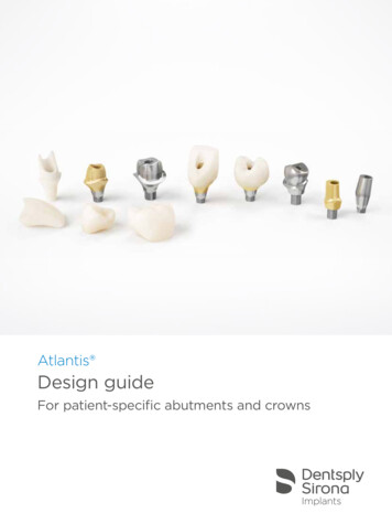
Ramos et al5.0Fig 1 Calibration curve determined through linear regressionby placing TB increments of 0.1 µL to 0.7 µL (best line fit) usinga fraction of a color marker volume in water.y 0.0062x 0.2223R2 .52.2382.01.51.442Series 11.00.7050.50.11200200400600800TB (µL)the implant and abutment obtained by torquing theconnecting screw.7–9 Considering the behavior of bolted joints, the clamping force between two surfaces ismaximized and most stable when no gaps are presentbetween them.10The placement of the implant-abutment interfaceat the level of alveolar bone has been associated withthe presence of inflammatory cell infiltrate and boneloss.11 It has been demonstrated that following implant surgery, remodeling occurs and may lead to areduction in bone dimension, both horizontally andvertically.12 Some studies have shown that implantcomponents and bone appear to tolerate some degree of lack of fit,13–15 but the degree of marginal fitthat can be considered clinically acceptable has notbeen established.16–18 Several methods have beenproposed to characterize the implant-abutment interface fit. Studies have most frequently investigated thesealing capability by observing bacterial4–6,19 or colormarker migration toward or from the implant well.4Direct observations of the implant-abutment interface have also been performed by radiograph,20 scanning electron microscopy (SEM),21,22 and hard x-raysynchrotron radiation.23 Another possibility is a crosssectional analysis and evaluation of the misfit takenas a function of implant radius, which allows a morecomprehensive observation of adaptation along theimplant-abutment interface.24 It has generally beenshown that most implant-abutment interfaces do notresult in a sealed connection.Recently, sealing tests of external hexagon implantabutment interfaces showed that stock abutmentsfrom different manufacturers presented similar leakage in temporal observations.25 In this study, it washypothesized that customized universal castable longabutments (UCLAs) from several manufacturers wouldpresent improved sealing due to the presence of a prefabricated cobalt chromium (CoCr) margin at the interface compared to UCLA abutments without it. Thisstudy tested the following hypotheses: (1) the sealingcapability of implant-abutment connections with aprefabricated CoCr margin will present improved resistance to microleakage at several incubation timescompared to connections without this margin and (2)subsequent SEM observation of the implant-abutmentmarginal fit would reflect the results from the sealing testing, where groups presenting higher leakagewould also present a qualitatively poorer interface fit.MATERIALS AND METHODSSample PreparationOne-hundred and twenty 4.1-mm-diameter external hexagon implants (SIN) were randomly dividedinto two groups (n 60 each) to receive UCLA abutments from six different manufacturers. One groupcomprised implants receiving customized UCLA abutments with a prefabricated CoCr margin and a remaining body of plastic, and the other group comprised fullplastic UCLA abutments from the same manufacturers (n 60 each). The groups were as follows: groupM (Microplant), group I (Impladen, Prodem), group S(SIN,), group SV (Signo Vinces ), group T (Titanium Fix,AS Technology Componentes Especiais), and group B(Bionnovation Biomedical).Abutments from both groups were sent to a commercial laboratory to be waxed and cast in a CoCr alloy114 Volume 29, Number 1, 2014 % 48,17(66(1&( 38%/,6 ,1* &2 ,1& 35,17,1* 2) 7 ,6 '2&80(17 ,6 5(675,&7(' 72 3(5621 / 86( 21/ 12 3 57 0 %( 5(352'8&(' 25 75 160,77(' ,1 1 )250 :,7 287 :5,77(1 3(50,66,21 )520 7 ( 38%/,6 (5
Ramos et al(Wirobond-280, Bego) by an experienced technicianwho was blind to abutment brand. A total of 12 groupswere formed according to the presence or absenceof the prefabricated CoCr margin. Abutments wereseated and screwed on their respective implants andtorqued to 32 Ncm using a torquemeter (SIN), following the manufacturer’s recommendation.of TB, no subsequent absorbance measurement wasmade. The arithmetic average of the three absorbancevalues was determined and used for statistical analyses. Repeated measures analysis of variance (ANOVA)at 95% level of significance and Tukey test for multiplecomparisons were utilized.SEM ObservationSealing Capability TestThe implants and their abutments were first subjectedto a sealing capability test and then to SEM observation of the interface. To quantify the range of the colormarker, toluidine blue (TB) that implants could leakto distilled water, a calibration curve was determinedthrough linear regression. TB increments of 0.1 to0.7 µL (best line fit) were added with an automatedpipette (Eppendorf Research Pro) to 0.7 mL of distilledwater placed in 2.0-mL vials. The absorbance of TBdissolved in water (Fig 1) was quantified with a spectrophotometer calibrated to a wavelength of 560 nm(Fluostar Optima; BMG, Labotech).The maximum amount of 0.7 µL was determinedfrom a previous study,25 which indicated that this volume was enough to fill the implant well and remain freefrom contact with the apical region of the abutmentscrew. Samples from each increment were analyzed inthe spectrophotometer calibrated to a wavelength of560 nm to acquire the absorbance values, which wereused to compose the absorbance curve. The startingpoint to formulate the absorbance curve was pure distilled water without color marker (blank). The calibration curve was determined by linear regression (bestline fit) considering the absorbance as a function ofTB amount.Subsequently, 0.7 µL of TB was dispensed at themost apical portion of the implant well by means of anautomated pipette. Implants were vertically held by avise connected to the bench to allow abutments to betorqued to 32 Ncm, as per manufacturer recommendations, using a torque wrench (TMEC, SIN—Sistemade Implante Nacional). The connected implants wereplaced into 2.0 mL vials (Eppendorf Research Pro) filledwith 1.5 mL of distilled water assuring that only theimplant-abutment interface remained immersed, andnot the interface between the abutment and screw.The capped vials containing the implants were kept atroom temperature throughout testing.Samples of 100 µL (n 3 for each implant) were acquired at 1, 3, 6, 24, 48, 72, 96, and 144 hour incubationtimes using an automated pipette. Each sample wastransferred from the respective vial to a microplate (TPP96, Techno Plastic Products AG) for absorbance evaluation. Immediately after measurements, the contents ofthe microplate were returned to the vials containingthe implants. When a group presented total leakageSpecimens were subjected to marginal fit evaluation inthe SEM (Model 3500S, Hitachi Ltd.) at a 15-Kv acceleration voltage and 35 magnification. The inspection involved qualitative observation of representative areasof the implant-abutment interface fit. Specimens of allgroups were subjected to the same imaging protocolwhere they were first evaluated across the observableinterface and images of representative sections of theinterface were acquired, as perpendicular as possibleto the junction.RESULTSThe calibration absorbance curve was linear with respect to the TB 0.1 µL increments (up to 0.7 µL) dissolved in 2.0 µL of distilled water presenting an R2 of0.98424 (Fig 1).Two-way ANOVA repeated measures (time, margin,and manufacturers) showed that there was no significant difference in the release of TB between groupspresenting the prefabricated CoCr margin (P .05) andgroups without it (P .05). The absorbance means and95% confidence intervals as a function of incubationtime for the different implant abutment systems arepresented in Figs 2a and 2b.As a general trend, all implant abutment systems, regardless of the presence of the prefabricated CoCr margin, presented an increase in absorbance as a functionof time, with a significant difference observed betweenincubation times for some groups (P .05). However,the fastest complete release of TB occurring at 1 hourwas observed for groups M, Sv, and TF without theCoCr margin. Group I without the margin resultedin the complete release of TB at 3 hours, followed bygroups S at 24 hours and B at 96 hours (Fig 2a).Groups with the CoCr margin presented no statisticaldifference (P .059) compared with groups where themargin was absent. However, total release of TB generally occurred after longer incubation times (Fig 2b). Forgroup S, maximum release occurred at 6 hours followedby groups SV, TF, and B at 24 hours. Groups M and Ishowed the complete release at 72 hours (Fig 2b).SEM observation showed the presence of gaps inall groups even at low magnifications (Figs 3 and 4).An evidently larger misfit was observed for groups M(Fig 3a) and TF (Fig 3e) without the CoCr margin.The International Journal of Oral & Maxillofacial Implants 115 % 48,17(66(1&( 38%/,6 ,1* &2 ,1& 35,17,1* 2) 7 ,6 '2&80(17 ,6 5(675,&7(' 72 3(5621 / 86( 21/ 12 3 57 0 %( 5(352'8&(' 25 75 160,77(' ,1 1 )250 :,7 287 :5,77(1 3(50,66,21 )520 7 ( 38%/,6 (5
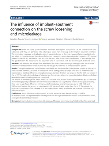
Ramos et al0.101h3h6h24 h48 h72 h96 h144 ISVTFBIOa0.101h3h6h24 h48 h72 h96 h144 ISVTFBIObFig 2 Color marker release as a function of incubation time for groups (a) without and (b) with the 2-mm CoCrshoulder. M: Microplant; S: SIN; I: Impladen; SV: Signo Vinces; TF: Titanium Fix; BIO: Bioinnovation.DISCUSSIONDespite the high success rates of dental implantology,the quest to reduce long-term biological complicationshas fostered the development of new implant designsaimed to maintain long-term peri-implant tissue health.Changes in implant geometry and surface treatment aswell as the trend toward the use of internal implantabutment connections have shown that the currentcriteria for implant treatment success should be recon-sidered in light of industrial and clinical advances.26Remarkably, decades after the launch of the externalhexagon system, this connection design is still the mostused worldwide.21,27 An evaluation of the market shareof implant connections in Brazil, where all the evaluated components in this study were fabricated, showedthat the external hexagon represents 58% of the sales,followed by internal conical connections (27%), and internal hexagon (15%).28116 Volume 29, Number 1, 2014 % 48,17(66(1&( 38%/,6 ,1* &2 ,1& 35,17,1* 2) 7 ,6 '2&80(17 ,6 5(675,&7(' 72 3(5621 / 86( 21/ 12 3 57 0 %( 5(352'8&(' 25 75 160,77(' ,1 1 )250 :,7 287 :5,77(1 3(50,66,21 )520 7 ( 38%/,6 (5
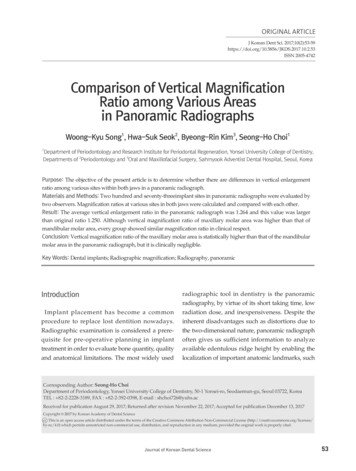
Ramos et alabcdefFig 3 SEM micrographs of the implant-abutment interface for groups without a 2-mm CoCr shoulder: (a) Microplant, (b) Impladen,(c) SIN, (d) Signo Vinces, (e) Titanium Fix, (f) Bioinnovation.abcdefFig 4 SEM micrographs of the implant-abutment interface for groups with a 2-mm CoCr shoulder: (a) Microplant, (b) Impladen, (c)SIN, (d) Signo Vinces, (e) Titanium Fix, (f) Bioinnovation.The present in vitro study evaluated the sealing capability and marginal fit of one external hexagon implantsystem using customized UCLA connections with orwithout a prefabricated margin, each from six differentmanufacturers by spectrophotometric quantificationof microleakage.4,24,25 Of clinical significance is that irrespective of the presence of the prefabricated CoCrmargin, all systems presented, at some observation timepoint, leakage of the color marker placed in the implantwell. However, two groups that did not present the prefabricated margin revealed a consistently larger gap thatresulted in the fastest complete color marker release.Interestingly, another system, also without the prefabricated margin, presenting total color marker release at 1hour depicted gaps visually smaller and similar to othergroups, which suggests that microscopic marginal observation of implant-abutment interfaces alone fails tobe an accurate predictor of sealing capability.The International Journal of Oral & Maxillofacial Implants 117 % 48,17(66(1&( 38%/,6 ,1* &2 ,1& 35,17,1* 2) 7 ,6 '2&80(17 ,6 5(675,&7(' 72 3(5621 / 86( 21/ 12 3 57 0 %( 5(352'8&(' 25 75 160,77(' ,1 1 )250 :,7 287 :5,77(1 3(50,66,21 )520 7 ( 38%/,6 (5
Ramos et alExtrapolation of the present findings that indicatedunimpeded leakage of toluidine blue from the implantwell to the external media, to the clinical scenario,which may include a two-way path for a variety ofbacteria under loading, should be made with caution.However, such bidirectional fluid leakage and bacterialpenetration has been described for implant-abutmentsystems also in the absence of mechanical loading.29–31Specific evaluations on internal conical implant-abutment connections have also pointed out their inabilityto hinder endotoxin leakage from the implant well.32When dynamic loading was incorporated into bacterial leakage testing (E Coli, which measures 1.1 to1.5 µm in diameter and 2 to 6 µm in length), all fiveevaluated implant systems, including external and internal connections, showed bacterial leakage.33Explanations for the presence of an implant-abutment gap include imprecise machining of implantparts, excessive torque during abutment installationleading to part distortion, and improper male-femaleadaptation among others.34 Taking into considerationthe careful adaptation and torque applied to the implants with or without a CoCr margin in this study, theleakage of the color marker was probably because ofimprecise machining of the implant male hexagonpart and/or abutment female hexagon. When placedat or below the crestal bone level, the presence of thisinterface may be critical to the health of peri-implanttissues.35 Although some companies recommend thecasting of abutments without the CoCr shoulder for thefinal restoration, our data suggest that even in a lesssensitive connection type, ie, the external hex, a verypoor fit can be expected. This may be aggravated in internal connections where casting and slight distortionsmay compromise the fit and close contact between theimplant walls and abutment surface. Therefore, regardless of implant-abutment connection type, abutmentconfigurations omitting a metal shoulder may be indicated exclusively for provisional restorations.From a mechanical standpoint, oblique loads aremainly born by the abutment screw in external hexagon systems, whereas in internal connections a shiftin load distribution occurs toward the implant walls,abutment, and screw. Therefore, less micromovementseems to occur in internal connections, which ultimately leads to a higher probability of survival whensubjected to fatigue loading.36 In addition, most internally connected systems present a mismatch betweenthe abutment diameter and the implant at the crestallevel, a concept known as platform-switching. Suchconfiguration places the implant-abutment gap awayfrom the bone with a directly proportional relationship between the amount of mismatch and the level ofbone preservation reported to occur in a randomizedclinical trial.37,38 Therefore, considering that screwedinternal connections have also been shown to fail inproviding a hermetic implant-abutment seal,4 the useof the platform-switching concept seems to be moresuitable for internal compared to external connectionsin terms of probability of survival, as recently reported.39The differences in hardness and moduli betweenCoCr alloy (E 210 GPa, ASTM F75) and CP Ti (E 100GPa, ASTM F67) may be a factor accelerating the failureof a restored implant system, which is yet to be elucidated. A somewhat similar scenario occurs with Y-TZPabutments (E 210 GPa) connected to Ti CP or Ti6Al4Vimplants (E 110 GPa, ASTM F136) where a disparityin modulus is found. Although Y-TZP is a ceramic, itstransformation toughening effect makes the comparison with a metal such as CoCr alloy fair from themechanical properties standpoint. A recent short-term(5 years) randomized clinical trial40 as well as a systematic review have indicated not statistically differentsurvival rates between Ti and Y-TZP abutments,41 indicating that no current evidence is available to infer theimpact of material differences between implants andabutments on prosthesis longevity. Longer follow-upsare desired, especially with CoCr alloy abutments, forfurther clarification.Another potential subject of concern is the possibility of galvanic corrosion, occurring due to the contactbetween two dissimilar metals in an electrolytic solution.42 The composition of the CoCr alloy used in theabutment of our study includes the following: C 0.042,Si 0.36, Mn 0.40, Cr 27.56, Ni 0.17, Fe 0.24,Co 65.82, Mo 5.13, and N 0.165. These amountsfollow the ASTM F75 standard for Cobalt-based alloys.However, galvanic corrosion represents an importantconcern and has been addressed in several studies. Aninvestigation concerning the CoCr alloy susceptibility togalvanic corrosion when in contact with commerciallypure Ti, Ti alloys, and steel alloys, found that the CoCr alloy and Ti couple was stable when subjected to an electrochemical open-circuit potential measurement testand a potentiostatic passive film-corrosion measurement test.43 Another study evaluated the galvanic corrosion between Ti and several alloys including CoCr byelectrochemical means, scanning electron microscopy(SEM), and Auger spectrometry. Very low corrosion rates(10-6 to 10-8) were found for CoCr alloys, which werenot different from high noble alloys.44 Specific evaluations using artificial saliva as the medium at 37 C of thecombination between CoCr frameworks fixed to titanium dental implants were made. After electrochemical testing, morphologic evaluations of the surface andsections detected galvanic corrosion activity, howeverto insignificant levels. Authors also emphasized thatthe clinical perception of metallic taste, suggestingongoing galvanic corrosion activity, may be elicitedwith currents averaging 75 µA/cm.2,45 The maximum118 Volume 29, Number 1, 2014 % 48,17(66(1&( 38%/,6 ,1* &2 ,1& 35,17,1* 2) 7 ,6 '2&80(17 ,6 5(675,&7(' 72 3(5621 / 86( 21/ 12 3 57 0 %( 5(352'8&(' 25 75 160,77(' ,1 1 )250 :,7 287 :5,77(1 3(50,66,21 )520 7 ( 38%/,6 (5
Ramos et alcurrent density level observed for CoCr alloys was11.6 µA/cm2, which is substantially inferior to the levelsrequired to trigger such sensations.46 The concern ofbiologic and mechanical risks of galvanic corrosion between predominantly base alloys and Ti should not beoverlooked. From a biologic standpoint, the implicationsof electrical corrosion and their potential effect on periimplant tissues are yet to be elucidated.47 However, ifformulated as per ASTM F75, as in the present study, galvanic corrosion, if present, may be clinically negligible,but certainly deserves close observation. Lastly, from amechanical standpoint, a recent systematic review hasindicated abutment screw loosening as the chief complication in implant restorations, whereas no complications related to galvanic corrosion were reported.48The magnitude of the implant–abutment gap hasreceived significant attention in the past,5,49 and different methodologies have been utilized for such investigation.8,9,24,50 The implant-abutment connectiontype has been one of the design parameters commonly changed by implant manufacturers. Rationalesfor changing the implant-abutment connection design include an attempt to establish better prostheticstability and to decrease the implant-abutment gapthat has been reported to occur in many implant systems.5,24,49 Internal connections presenting improvedsealing capability4 have also been shown to result in ahigher probability of survival.51 Therefore, an adequatefit between components seems to influence the overall system’s mechanical performance. Locking taperconnections have been shown to provide a bacterialseal through cold welding occurring at the implantabutment connection,5 and remarkably high characteristic strength and reliability have been observed forcrowns placed on such a system.52,53 Future studies addressing interface fit of custom abutments in externalconnections in tandem with fatigue testing to elucidate failure mechanisms and reliability are warranted.A recent investigation incorporating the use of hardx-ray synchrotron radiation under load application hasbeen described in the evaluation of implant-abutmentinterfaces. Such an analytical tool allows not only qualitative imaging but also quantitative measurements ofthe interface under static and dynamic loading, presenting an interesting potential for future characterization of the implant-abutment mating zone.23Our first hypothesis, which postulated that the sealing capability of implant-abutment connections witha prefabricated cobalt-chromium (CoCr) margin wouldpresent improved resistance to microleakage compared to connections without it, was rejected. SinceSEM observation showed different levels of fit in UCLAabutments without the prefabricated margin and thesame levels of lack of sealing, the second hypothesiswas also rejected.ACKNOWLEDGMENTSThis study was supported by Fapesp Grant 2010/06152-9, andSIN–Sistema de Implante Nacional. The authors would like to acknowledge the skillful work of dental technician Giovani Heckert.The authors reported no conflicts of interest related to thisstudy.REFERENCES1. Jung RE, Pjetursson BE, Glauser R, Zembic A, Zwahlen M, Lang NP.A systematic review of the 5-year survival and complication rates ofimplant-supported single crowns. Clin Oral Implants Res 2008;19:119–130.2. Papaspyridakos P, Chen CJ, Chuang SK, Weber HP, Gallucci GO. Asystematic review of biologic and technical complications with fixedimplant rehabilitations for edentulous patients. Int J Oral MaxillofacImplants 2012;27:102–110.3. Papaspyridakos P, Chen CJ, Singh M, Weber HP, Gallucci GO. Success criteria in implant dentistry: A systematic review. J Dent Res2012;91:242–248.4. Coelho PG, Sudack P, Suzuki M, Kurtz KS, Romanos GE, Silva NR. Invitro evaluation of the implant abutment connection sealing capability of different implant systems. J Oral Rehab 2008;35:917–924.5. Dibart S, Warbington M, Ming FS, Skobe Z. In vitro evaluation of theimplant-abutment bacterial seal: The locking taper system. Int J OralMaxillofac Implants 2005;20:732–737.6. Duarte ARC, Rosetti PH, Rossetti LMN, Torres SA, Bonachela WC. Invitro sealing ability of two materials at five different implantabutment surfaces. J Periodontol 2006;77:1828–1832.7. McGlumphy EA, Mendel DA, Holloway JA. Implant screw mechanics.Dent Clin North Am 1998;42:71–89.8. Jorneus L, Jemt T, Carlsson L. Loads and designs of screw joints forsingle crowns supported by osseointegrated implants. Int J OralMaxillofac Implants 1992;7:353–359.9. Patterson EA, Johns RB. Theoretical analysis of the fatigue life of fixture screws in osseointegrated dental implants. Int J Oral MaxillofacImplants 1992;7:26–33.10. Bickford JH. An Introduction to the Design and Behavior of BoltedJoints. New York: Marcel Decker, 1981.11. Broggini N, McManus LM, Hermann JS, et al. Persistent acute inflammation at the implant-abutment interface. J Dent Res 2003;82:232–237.12. Cardaropoli G, Lekholm U, Wennstrom JL. Tissue alterations atimplant-supported single-tooth replacements: A 1-year prospectiveclinical study. Clin Oral Implants Res 2006;17:165–171.13. Carr AB, Gerard DA, Larsen PE. The response of bone in primatesaround unloaded dental implants supporting prostheses with different levels of fit. J Prosthet Dent 1996;76:500–509.14. Kan JYK, Rungcharassaeng K, Bohsali K, Goodacre CJ, Lang BR. Clinical methods for evaluating implant framework fit. J Prosthet Dent1999;81:7–13.15. Jemt T, Book K. Prosthesis misfit and marginal bone loss in edentulous implant patients. Int J Oral Maxillofac Implants 1996;11:620–625.16. Hecker DM, Eckert SE. Cyclic loading of implant-supported prostheses: Changes in component fit over time. J Prosthet Dent 2003;89:346–351.17. Tan KB. The clinical significance of distortion in implant prosthodontics: is there such a thing as passive fit? Annals Academy MedSingapore 1995;24:138–157.18. Watanabe F, Uno I, Hata Y, Neuendorff G, Kirsch A. Analysis of stressdistribution in a screw-retained implant prosthesis. Int J Oral Maxillofac Implants 2000;15:209–218.19. Deconto MA, Salvioni AD, Wassall T. In vitro microbiological bacterialseal analysis of the implant/abutment connection in morse taperimplants: A comparative study between 2 abutments. ImplantDentistry 2010;19:158–166.The International Journal of Oral & Maxillofacial Implants 119 % 48,17(66(1&( 38%/,6 ,1* &2 ,1& 35,17,1* 2) 7 ,6 '2&80(17 ,6 5(675,&7(' 72 3(5621 / 86( 21/ 12 3 57 0 %( 5(352'8&(' 25 75 160,77(' ,1 1 )250 :,7 287 :5,77(1 3(50,66,21 )520 7 ( 38%/,6 (5
Ramos et al20. Papavassiliou H, Kourtis S, Katerelou J, Chronopoulos V. Radiographical evaluation of the gap at the implant-abutment interface.J Esthetic Rest Dent 2010;22:235–250.21. Tsuge T, Hagiwara Y, Matsumura H. Marginal fit and microgaps ofimplant-abutment interface with internal anti-rotation configuration. Dent Mater J 2008;27:2
of 0.1% toluidine blue in the implant wells before abutment torquing. Implant-abutment samples were placed into 2.0-mL vials containing 0.7 mL of distilled water to maintain the implant-abutment interface, and aliquots of 100 µL of water were retrieved at 1, 3, 6, 24, 48, 72, 96, and 144 hour incubation times for measurement