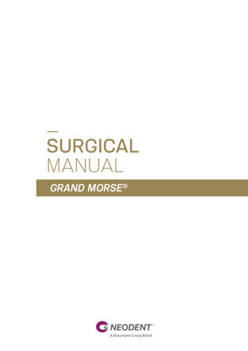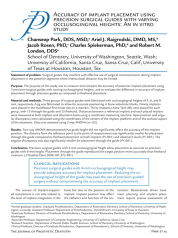
Transcription
Technical InformationStraumann BLX Implant SystemBasic Information702115.indd 124/04/2022 09:57
702115.indd 224/04/2022 09:57
Table of Contents1. The Straumann BLX Implant System 32. Implant 42.1Design and specification 3. Connection 3.1TorcFit connection 4. Instruments 5574.1VeloDrill 84.2External irrigation when using Drill Extender 84.3Alignment pins and depth gauges 94.4Implant Depth Gauge 94.5Implant Driver 104.6Ratchet and Torque Control Devices 114.7Straumann Modular Cassette 124.8Setup for BLX freehand surgery 125. Surgical procedure 135.1Preoperative planning 135.2Implant bed preparation 185.3Implant pick up 265.4Implant placement 275.5Gap management 305.6Primary implant closure 316. Prosthetic workflow overview 6.1Abutment overview 32326.2Color coding 336.3Overview of prosthetic components 347. Important considerations 387.1Implant base concept 387.2How to verify correct Impression Post seating 397.3How to verify correct final abutment seating 397.4Removal of finally tightened TorcFit abutments 408. Soft tissue management 702115.indd 14418.1Overview of Consistent Emergence Profiles 428.2Always communicate the selected healing abutment to the dental lab 4424/04/2022 09:57
9. Temporary restoration 459.1 Healing Abutment – Titanium grade 4 459.246Temporary Abutment – titanium alloy (TAN) 9.3 Immediate Temporary Abutment – titanium alloy (TAN) 479.4 Temporary Abutment – Polymer with titanium-alloy inlay (VITA CAD-Temp /TAN) 4810. Impression taking 4910.1 Conventional implant level impression taking 4910.2 Digital impressions: Straumann CARES Mono Scanbody 5011. Final restoration 5111.1 Straumann Screw‑retained Abutments 5111.2 Straumann Variobase 5311.3 Straumann Anatomic Abutments 5711.4 Straumann Gold Abutments 5811.5 Straumann Novaloc Abutments 5911.6 Straumann CARES Abutments 6011.7 Straumann Screw-retained Bars and Bridges (SRBB) 6011.8 Straumann CARES Scan & Shape 6211.9 Smile in a Box 6412. Further Information 65About this guideThis surgical and prosthetic procedure describes the steps required for implantation and restoration of the Straumann BLX Implant System. The Straumann BLX Implant System is recommended for use only by clinicians with advanced surgical skills. It is assumed that the user isfamiliar with placing dental implants. Not all detailed information will be found in this guide.Reference to existing Straumann procedure manuals will be made throughout this document.Not all products shown are available in all markets.702115.indd 224/04/2022 09:57
1. The Straumann BLX Implant SystemThe Straumann BLX Implant System offers Bone Level implants (BLX) that are designed for high primary stability and immediate treatment procedures.The Straumann BLX Implants are made from the material Roxolid with the SLActive and SLA surface and are available inthe endosteal diameters 3.5 mm to 6.5 mm, with length options from 6 mm to 18 mm for the diameter up to 5.0 mm,and 6 mm to 16 mm for diameters 5.5 mm and 6.5 mm. A unified color code simplifies identification of instruments andimplants for the available endosteal diameters.The Straumann BLX prosthetic components are identified with RB (Regular Base) and WB (Wide Base), corresponding to theimplant neck diameters of 3.5 mm and 4.5 mm, respectively.Straumann BLX ImplantColor code 3.5 mm 3.75 mm 4.0 mm 4.5 mm 5.0 mm(white)(red)(gray)(green)(magenta)Prosthetic BaseRB (Regular Base) 5.5 mm 6.5 mm(brown)(black)WB (Wide Base)ConnectionTorcFit PictureSLActive Availablelengths6 3068 061.930810 061.931012 061.931214 061.931416 061.931618 mm061.3318061.4318061.5318061.6318061.7318–SLA Availablelengths6 5068 061.950810 061.951012 061.951214 061.951416 18 –To obtain more information about the indications and contraindications related to each implant, please refer to the corresponding instructions for use. Instructions for use can be found at www.ifu.straumann.com.Note:Particular care should be taken when placing small-diameter Roxolid implants ( 3.5 mm) in the molar region or otherhigh-load situations due to the risk of implant overload.3702115.indd 324/04/2022 09:57
2. Implant2.1ADesign and specificationBCDEHMLStraumann BLX Implant 4.5 mmPTFGStraumann BLX Implant 3.5 mm 3.75 mm 4.0 mm 4.5 mm 5.0 mm 5.5 mm 6.5 mm[A] Maximum outer diameter 3.5 mm 3.75 mm 4.0 mm 4.5 mm 5.0 mm 5.5 mm 6.5 mm[B] Neck diameter 3.4 mm 3.5 mm 4.5 mm[C] Platform diameter 2.9 mm[D] Connection diameter 2.7 mm[E] 22.5 bevel height0.1 mm0.12 mm[F] Apical diameter, body[G] Apical diameter, threads0.33 mm 1.9 mm 2.75 mm 2.2 mm 2.9 mmNumber of apical cutting edges 3.6 mm 3.5 mm2 4.0 mm 5.2 mm4[L] Implant lengths: 6 mm, 8 mm[H] Neck height1.0 mm[M] Micro threads height0.5 mm[P] Thread pitch*1.7 mm1.8 mm2.0 mm1.9 mm2.1 mm2.3 mm[T] Thread spacing0.85 mm0.9 mm1.0 mm0.95 mm1.05 mm1.15 mm[L] Implant lengths: 10 mm, 12 mm, 14 mm[H] Neck height1.7 mm[M] Micro threads height0.85 mm[P] Thread pitch*2.1 mm2.2 mm2.25 mm2.5 mm2.3 mm2.5 mm2.7 mm[T] Thread spacing1.05 mm1.1 mm1.125 mm1.25 mm1.15 mm1.25 mm1.35 mm[L] Implant lengths: 16 mm, 18 mm4702115.indd 4[H] Neck height2.0 mm[M] Micro threads height1.0 mm[P] Thread pitch*2.5 mm2.6 mm2.7 mm2.8 mm2.7 mm2.8 mm3.1 mm[T] Thread spacing1.25 mm1.3 mm1.35 mm1.4 mm1.35 mm1.4 mm1.55 mm* Implant advances by this amount with every rotation.24/04/2022 09:57
3. Connection3.1TorcFit connectionThe Straumann BLX Implant features the intuitive TorcFit connection. This connection supports self-guiding insertion, for clear-cut tactile feedback. Six positions enable a simple yet flexible alignment and outstanding protection against rotation.All BLX Implants have the same inner geometry regardless of the diameter of the implant. This allows the useof one set of prosthetic components (“RB/WB abutments”) and simplifies the prosthetic steps. In addition,a wide emergence profile can be created on top of WB implants (“WB abutments”).Improved Torx with six positions:ѹ Allows transmission of high torquesѹ Simple yet flexible implant and abutment alignment7 conical prosthetic connection:ѹ High mechanical stability and stress distributionѹ Exact implant-abutment fitѹ Narrow emergence profile creates space for soft tissuesѹ Clear feedback of final position by friction fit22.5 shoulder prosthetic connection:ѹ High mechanical stabilityѹ Exact implant-abutment fitѹ Extra wide emergence profiles(implants with diameter 5.0 mm)ѹ Divergence compensation for bridgesFlat top portion:ѹ High accuracy for impression componentsѹ Flat sealing for healing and temporary components toprotect inner conus5702115.indd 524/04/2022 09:57
Same inner geometry regardless of the diameter of the implantѹ A single prosthetic range to manage all implant diameters (“RB/WB”)ѹ Simplified prosthetic stepsѹ Same implant driver for all implantsPrecise machined shoulder for optional wide emergence profile (diameter 5.0 mm)ѹ Free choice of implant regardless of prosthetic volume to restore 3.5 mm 3.75 mm 4.0 mm 4.5 mm 5.0 mm 5.5 mm 6.5 mm6702115.indd 624/04/2022 09:57
4. InstrumentsThe Straumann BLX Implant System is suppliedwith a specific set of instruments.The instruments have depth marks at 2 mm intervalsthat correspond to the available implant lengths.The first bold mark on the drills represents 10 mmand 12 mm, where the lower edge of the mark corresponds to 10 mm and the upper edge to 12 mm.The second bold mark on the long drills represents16 mm and 18 mm, where the lower edge of the markcorresponds to 16 mm and the upper edge to 18 mm.18 mm16 mm14 mm12 mm10 mm8 mm6 mm4 mm12345671. Needle Drill: 026.00562. Pilot Drill, long: 066.17013. Alignment Pin: 046.7994. Drill 6, long: 066.17065. Depth Gauge 046.8046. BLX Implant 4.5 / 12 mm: 061.63127. Implant Depth Gauge: 066.2000Warning: Due to the function and design of the drills,the drill tip is up to 0.5 mm longer than the insertiondepth of the implant. For example, if you drill until the 10 mm marking the actual osteotomy has a0.5 mmdepth of 10.5 mm.7702115.indd 724/04/2022 09:57
4.1VeloDrill The BLX VeloDrill line in the Straumann Dental Implant System is delivered color-coded, the color corresponding to thespecific implant diameter. For precise depth control, VeloDrills are compatible with a disposable drill stop system (refer toStraumann Drill Stop, Basic Information (702874/en)).Needle drillColorDrillNo. 1 (pilot)DrillNo. 2DrillNo. 3DrillNo. 4DrillNo. 5DrillNo. 6DrillNo. 7DrillNo. 8DrillNo. 9–Picture(short)Diameter 1.6 mm 2.2 mm 2.8 mm 3.2 mm 3.5 mm 3.7 mm 4.2 mm 4.7 mm 5.2 mm 6.2 mmStepdiameterNANA 2.5 mm 3.0 mm 3.3 mm 3.6 mm 3.9 mm 4.4 mm 4.9 mm 5.7 ssteel4.2 External irrigation when using Drill ExtenderThe Stop Ring reduces the effectiveness of the irrigation when a Drill Extender is used. In this caseuse additional external irrigation (e.g with a syringe) to ensure proper cooling of the osteotomyduring drilling.8702115.indd 824/04/2022 09:57
4.3Alignment pins and depth gaugesAlignment pins and depth gauges are available for accurate depth measurements and alignment of orientation and position of the osteotomy. Their diameters and colors correspond to the drill diameters and arecompatible with all Straumann Dental Implant Systems.The tip and the groove are both 1.0 mm long. This allows distortion measurements on an interoperativeradiograph.Pilot Drill 1 2.2 mmAlignment Pin 2.2 mmDrill 2 2.8 mmDepth Gauge 2.8 mm18 mm16 mm14 mm12 mm10 mm8 mm6 mm4 mm1 mm1 lant Depth GaugeThe Implant Depth Gauge is used for accurate depth measurement and tactile examination of the osteotomy.Blue end: use to examine osteotomy made using Drill No. 1 ( 2.2 mm)Yellow end: use to examine osteotomy made using Drill No. 2 ( 2.8 mm) and widerThe Implant Depth Gauge is made of titanium alloy (TAN) and is compatible with all Straumann DentalImplant Systems.12 mm10 mm2.0 mm1.5 mmImplant Depth Gauge, 066.20009702115.indd 924/04/2022 09:57
4.5Implant DriverSelect the appropriate implant driver type for pick-up and insertion of the Straumann BLX Implants.Implant Driver typeImplant Driver for HandpieceImplant Driver for Ratchet,screw-retainedImplant Driver for Ratchetshortmediumlongextra longshortmediumlongshortlongLength 21 mmLength 26 mmLength 31 mmLength 36 mmLength 21 mmLength 26 mmLength 31 mmLength 21 mmLength 31 mm066.4207066.4202066.4205066.4206Stainless steel066.4101066.4107066.4102066.4108066.4201Note: Consider the available intra oral space when selecting an implant driver. The long and extra-long versions are recommended for anterior only.Surgical Handle for TorcFit Implant DriverStainless steel066.4000The Implant Drivers for Handpiece (long (066.4102), extra long (066.4108)) are compatible with the Surgical Handle, forTorcFit Implant Driver. If manual surgical implant drivers are used to insert the implant, special attention is required toavoid overtightening.4 mm3 mm2 mm1 mm0 mm (Bone Level)The round markings on the implant drivers indicate the distance to the implant shoulder in 1 mm steps.10702115.indd 1024/04/2022 09:57
4.6Ratchet and Torque Control DevicesThe Ratchet is a two-part lever arm instrument with a rotary knob for changing the direction of force. It is supplied witha service instrument, which is used to tighten and loosen the head screw. The Holding Key (046.064) can be used tostabilize the Ratchet.Two different Torque Control Devices are available for defined torque transmission or for torque measurements, withmarkings of 15 Ncm / 35 Ncm and 35-50 Ncm / 80 Ncm, respectively. Choose the appropriate device depending on the intended use.Ratchet and Torque Control DevicesHolding KeyRatchetTorque Control Devicefor RatchetBLX Torque Control Devicefor Ratchet, SurgicalIntended useAuxiliaryTorque transmissionProstheticSurgicalTorque markingsNANA0 / 15 / 35 Ncm0 / 35 / 50 / 80 NcmArticle ss steelStainless steelStainless steelStainless steel, DLC coatedNote: To ensure prolonged perfect function and cleanability, the Ratchet must always be taken apart and the individual parts disinfected, cleaned and sterilized after use. Its function must be checked in good time before each use.Always use the Service Instrument to tighten the bolt of the Ratchet before use.Torque reading on Torque Control Device:35 Ncm50 Ncm11702115.indd 1124/04/2022 09:57
4.7Straumann Modular CassetteThe Straumann Modular Cassette is usedfor the sterilization and the secure storageof the surgical instruments and auxiliary instruments. For guidelines on how to cleanand sterilize the cassette, please refer toStraumann Modular Cassette, Basic Information (702527/en).4.8 Setup for BLX freehand surgeryA ModuleFully Tapered Tray041.761041.777Ratchet TrayImplant Depth Gauge Tray041.766Ratchet046.119041.771BLX TorqueControl066.1100Holding Key046.064Implant Depth Gauge066.2000Implant Driver for Ratchet066.4201066.4202AlignmentPin046.799Depth Gauge046.801Depth Gauge046.803Depth Gauge046.805Depth Gauge046.807Implant Driverfor Handpiece066.4101066.4102DrillExtender040.563Depth Gauge046.800Depth Gauge046.802Depth Gauge046.804Depth Gauge046.806longshortX VeloDrillTM066.1702066.1302SCS Screwdriverfor Ratchet046.400046.401046.402SCS Screwdriverfor Handpiece046.410046.411046.412SCS Screwdriver SetGrommet Tray 3 small 3 large041.764X VeloDrillTM066.1704066.1304X VeloDrillTM066.1706066.1306X VeloDrillTM066.1308Round Bur044.004044.003Needle Drill026.0056X VeloDrillTM066.1701066.1301X VeloDrillTM066.1703066.1303X VeloDrillTM066.1705066.1305X VeloDrillTM066.1707066.1307X VeloDrillTM066.1309For more information refer to Straumann Modular Cassette Selection Guide (702824/en).12702115.indd 1224/04/2022 09:57
5. Surgical procedureThe workflow for the surgical procedure for the Straumann BLX Implant System involves 3 steps:ѹ Preoperative planningѹ Implant bed preparationѹ Implant insertion5.1Preoperative planningProsthetic-driven planning is recommended, and close communication between the patient,dentist, surgeon and dental technician is imperative for achieving the desired esthetic result.To determine the topographical situation, axial orientation and the appropriate implants, makinga wax-up / set up using the previously prepared study cast is recommended. Subsequently, thetype of superstructure can be defined. The wax-up / set-up can later be used as the basis for acustom-made x-ray or drill template and for a temporary restoration.Note: Abutments should always be loaded axially. Ideally, the long axis of the implant is alignedwith the cusps of the opposing tooth. Extreme cusp formation should be avoided as this can leadto unphysiological loading.Mesiodistal bone availability is an important factor when choosing the implant type and diameter as well as the inter-implant distances if multiple implants are placed. The point of referenceon the implant for measuring mesiodistal distances is always the largest diameter of the implant.13702115.indd 1324/04/2022 09:57
The following three rules should be regarded as minimum guidelines:Rule 1Rule 2 1.5 mmRule 3 3 mm 1.5 mmRule 1: Distance to adjacent tooth atRule 2: Distance to adjacent implantsRule 3: The facial and palatal bone lay-bone levelat bone leveler must be at least 1.5 mm thick in or-A minimum distance of 1.5 mm fromA minimum distance of 3 mm betweensue conditions. Within this limitation,the implant adjacent tooth (mesialtwo adjacent implants (mesio distal) isa restoration-driven orofacial implantand distal) is recommended.recommended.position and axis should be chosen toder to ensure stable hard and soft tis-allow the placement of screw-retainedrestorations.Caution: An augmentation procedure is indicated if the orofacial bone wall is less than 1.5 mm or a layer of bone is missing on one or more sides. This technique should be employed only by dentists with adequate experience in the use ofaugmentation procedures.14702115.indd 1424/04/2022 09:58
5.1.1 X-ray Reference FoilThe vertical bone availability determines the maximum allowable length of the implant thatcan be placed. A minimum distance of 2 mm between the apex of the implant and the alveolar1.0 : 1nerve should be kept. For easierdeterminationof theBLXverticalbone availability, we recom 5.0mm Straumann ImplantStraumann BLX Impmend the use of an x-ray reference foil with X-ray Reference Sphere (049.076V4). 3.5 mmRB 3.75 mmRB 4.0 mmRB 4.5 mmRB 5.0 mmWB 5.5 mmWB 6.5 mmWB 3.5 mmRBThe BLX X-ray Reference Foil (065.0000) is used for measurement and comparison. It assists the0 selecting the suitable implant type, diameter and length. Similar to the distortions thatuser in2 3.75 mmRB 4.0 mmRB 4.5R024 x-rays, the implant dimensions are shown on the individual reference foils with theoccur in4668correspondingdistortion factors (1:1 to 1.7:1). Each magnification factor or scale is determined8101214161820222410by showing12 the X-ray Reference Sphere on the reference foil. First, compare the size of the14X-ray ReferenceSphere on the patient’s x-ray with the size of the Reference Sphere on the ref1618erence foil. Superimposethe two pictures to find the correct scale. Next, determine the spatial2022relations around24 the implant position, and establish the implant length and insertion depth.For more information regarding the preparation of a x-ray jig with the Reference Spheres, referto Straumann Dental Implant System, Basic Information (702084/en).1.1 : 1 5.5 mm 3.5 mmRB02 3.75 mmRBStraumann BLX Implant 4.0 mmRB 4.5 mmRB 5.0 mmWBStraumann BLX Imp 5.5 mmWB 6.5 mmWB 3.5 mmRB 3.75 mmRB 4.0 mmRB0426468101214161820222481012141618202224Note: For Straumann BLX Implants use only the x-ray reference foil specific to the BLXImplant (065.0000).To calculate the effective bone availability, use the following formula:X-ray Reference sphere 5 mm bone availability (X-ray*)Reference sphere diameter on the X-rayeffective boneavailability* Taking into consideration all implant-related anatomical structures(e.g. mandibular canal, sinus maxillaris, etc.)15702115.indd 1524/04/2022 09:58 4.5R
5.1.2 Planning softwareAnother possibility is digital planning with e.g. coDiagnostiX . This 3D diagnostics and implantplanning software is designed for the image-guided surgical planning of dental implants,including BLX Implants, which are included in the system’s digital library. Working with thesoftware is based on a patient’s medical image data, such as a CT (Computed Tomography)or DVT (Digital Volume Tomography) scan processed by coDiagnostiX .Planning includes the calculation of several views (such as virtual OPG or a 3-dimensional reconstruction of the image dataset), analysis of the image data and the placement of implants,abutments and drilling sleeves.coDiagnostiX software is designed for use by professionals with appropriate knowledge inimplantology and surgical dentistry. For further information, please refer to the coDiagnostiX manual.CARES Synergy workflowCARES Synergy provides real-timecommunication between the implantplanning software (coDiagnostiX )and the lab software (i.e. Straumann CARES ) and improves implant planning by visualizing the relationship between the proposed implant positionand the proposed restoration.For more information refer to Straumann Guided Surgery System Instruments, Basic Information(702526/en).16702115.indd 1624/04/2022 09:58
5.1.3 Straumann Pro Arch GuideFor intraoperative visual and three-dimensional orientation of the implant angulation (mesial/distal) and oral parallelization, use the Straumann Pro Arch Guide.The Pro Arch Guide is used in edentulous jaws for surgical implant placement. The Pro ArchGuide can be easily bent to adapt to the dental arch. It is secured by drilling into the symphysiswith a 2.2 mm Pilot Drill and a pin in the jaw. The drilling depth for the bone cavity of the pinis 10 mm. The drilling depth can be checked optically using the depth markings on the drills.Use the TS Hexagonal Screwdriver (046.420) to adjust and disassemble.Straumann Pro Arch Guide (026.0016)For further information on the treatment of edentulous patients and angulated placement ofBLX Implants, please refer to the Straumann Pro Arch, Basic Information (490.015/en).5.1.4 Bone density definitionCross sectional view of different types of bone quality*Type IType II / IIIType IVHardMediumSoftThick cortical bone with marrow cavityThin cortical bone with densetrabecular bone of good strengthVery thin cortical bone with low density trabecular bone of poor strength* Lekholm U, Zarb G. Patient selection and preparation in Tissue Integrated Prostheses. Branemark P I, Zarb G A, AlbrektssonT (eds). pp199–210. Quintessence, 1985.17702115.indd 1724/04/2022 09:58
5.2 Implant bed preparationThe Straumann Modular Cassette with specific instruments is used to prepare the implantbed. Different drill protocols should be employed depending on the bone density. This offersthe flexibility to adapt the implant bed preparation to the individual bone quality and anatomical situation.A quick guide to the surgical drill protocol is printed on the cassette and indicates the finaldrill recommended for each implant diameter and bone density.Numbers in brackets ( ): to a depth of 4 mm (for implant lengths 6 mm and 8 mm) and 6 mm (forimplant lengths 10 mm and longer) are only used to widen the coronal part of the implant bed.Bone densityFinal drill diameterImplant endosteal diameterCortical widening drill diameterNote: Every implant bed has to be initiated with the pilot drill ( 2.2 mm) to full implantlength. On the quick guide only the final drill is displayed. The clinician can decide whetheror not a sequence of drills with increasing diameters is used. Due to the self-cuttingproperties of the BLX Implant the implant bed can be underprepared in length by 2 mm withthe subsequent/final drills in soft bone (stepped). Rotate the drills in a clockwise direction,use an intermittent drilling technique and provide ample cooling with pre-cooled (5 C, 41 F)sterile saline solution. Do not exceed the recommended drill speed of 800 rpm.Hard bone drill protocol:Application of the hard bone drill protocol for a BLX Implant diameter with wider threads( 4.5 mm, 5.5 mm and 6.5 mm) in healed sites results in a small gap between the implantneck and the surrounding crestal bone. In such situations it is recommended to consider minorbone grafting around the implant neck. This may be accomplished by scraping a small amountof bone with a surgical chisel from the area surrounding the osteotomy (already exposed) andplacing it between the implant and the osteotomy.18702115.indd 1824/04/2022 09:58
5.2.1 Workflow for BLX 3.5 mmImplant bed preparation, illustrated with a BLX Implant 3.5 mm / 12 mm RBMark theimplantation siteNeedle Drill 1.6 mmPilot drillingCheck implant axisDecide onbone densityDrill No. 1Alignment Pin(pilot) 2.2 mm 2.2 mmFinalize implant bedAccording to bone densityDrill No. 2 2.8 mmDrill No. 3 3.2 mmImplantplacementDrill No. 4 3.5 mmSoftcMediumcHardc800 rpm800 rpm800 rpm800 rpm800 rpm026.0054066.1301066.1302066.1303066.1304BLX 3.5 mmSLActive 12 mm,Roxolid 15 rpmPreparation of cortical bone only- to a depth of 4 mm for implants with a length of 6 mm and 8 mm- to a depth of 6 mm for implants with a length of 10 mm to 18 mmNote: The Straumann BLX 3.5 Implants are not recommended to be used in the posterior area.Warning: Due to the function and design of the drills, the drill tip is up to 0.5 mm longer than the insertion depth of theimplant. For example, if you drill up to the 10 mm marking, the actual implant bed has a depth of 10.5 mm.Subcrestal implant placement: Consider the final implant position for drill depth and never undersize in length with theDrill No.1 (pilot).Immediate placement: In extraction sites where the implant only engages with its apical part, Drill No. 2 ( 2.8 mm) isrecommended as the final drill.19702115.indd 1924/04/2022 09:58
5.2.2 Workflow for BLX 3.75 mmImplant bed preparation, illustrated with a BLX Implant 3.75 mm / 12 mm RBMark theimplantation siteNeedle Drill 1.6 mmPilot drillingCheck implant axisDecide onbone densityDrill No. 1Alignment Pin(pilot) 2.2 mm 2.2 mmFinalize Implant Bedaccording to bone densityDrill No. 2 2.8 mmDrill No. 3 3.2 mmDrill No. 4 3.5 mmImplantplacementDrill No. 5 3.7 mmSoftcMediumcHardc800 rpm800 rpm800 rpm800 rpm800 rpm800 5BLX 3.75 mmSLActive 12 mm,Roxolid 15 rpmPreparation of cortical bone only- to a depth of 4 mm for implants with a length of 6 mm and 8 mm- to a depth of 6 mm for implants with a length of 10 mm to 18 mmWarning: Due to the function and design of the drills, the drill tip is up to 0.5 mm longer than the insertion depth of theimplant. For example, if you drill until the 10 mm marking, the actual implant bed has a depth of 10.5 mm.Subcrestal implant placement: Consider the final implant position for drill depth and never undersize in length with theDrill No.1 (pilot).Immediate placement: In extraction sites where the implant only engages with its apical part, Drill No. 2 ( 2.8 mm) isrecommended as the final drill.20702115.indd 2024/04/2022 09:58
5.2.3 Workflow for BLX 4.0 mmImplant bed preparation, illustrated with a BLX Implant 4.0 mm / 12 mm RBMark theimplantation siteNeedle Drill 1.6 mmPilot drillingCheck implant axisDecide onbone densityDrill No. 1Alignment Pin(pilot) 2.2 mm 2.2 mmFinalize Implant Bedaccording to bone densityDrill No. 2 2.8 mmDrill No. 3 3.2 mmDrill No. 4 3.5 mmImplantplacementDrill No. 5 3.7 mmSoftcMediumBLX 4.0 mmSLActive 12 mm,Roxolid Hardc800 rpm800 rpm800 rpm800 rpm800 rpm800 515 rpmPreparation of cortical bone only- to a depth of 4 mm for implants with a length of 6 mm and 8 mm- to a depth of 6 mm for implants with a length of 10 mm to 18 mmWarning: Due to the function and design of the drills, the drill tip is up to 0.5 mm longer than the insertion depth of theimplant. For example, if you drill until the 10 mm marking, the actual implant bed has a depth of 10.5 mm.Subcrestal implant placement: Consider the final implant position for drill depth and never undersize in length with theDrill No.1 (pilot).Immediate placement: In extraction sites where the implant only engages with its apical part, Drill No. 3 ( 3.2 mm) isrecommended as the final drill.21702115.indd 2124/04/2022 09:58
5.2.4 Workflow for BLX 4.5 mmImplant bed preparation, illustrated with a BLX Implant 4.5 mm / 12 mm RBMark theimplantation siteNeedle Drill 1.6 mmPilot drillingCheck implant axisDecide onbone densityDrill No. 1Alignment Pin(pilot) 2.2 mm 2.2 mmFinalize Implant Bedaccording to bone densityDrill No. 2 2.8 mmDrill No. 3 3.2 mmDrill No. 5 3.7 mmImplantplacementDrill No. 6 4.2 mmSoftBLX 4.5 mmSLActive 12 mm,Roxolid MediumHard800 rpm800 rpm800 rpm800 rpm800 rpm800 615 rpmWarning: Due to the function and design of the drills, the drill tip is up to 0.5 mm longer than the insertion depth of theimplant. For example, if you drill until the 10 mm marking, the actual implant bed has a depth of 10.5 mm.Subcrestal implant placement: Consider the final implant position for drill depth and never undersize in length with theDrill No.1 (pilot).Immediate placement: In extraction sites where the implant only engages with its apical part, Drill No. 4 ( 3.5 mm) isrecommended as the final drill.22702115.indd 2224/04/2022 09:58
5.2.5 Workflow for BLX 5.0 mmImplant bed preparation, illustrated with a BLX Implant 5.0 mm / 12 mm WBMark theimplantation siteNeedle Drill 1.6 mmPilot drillingCheck implant axisDecide onbone densityDrill No. 1Alignment Pin(pilot) 2.2 mm 2.2 mmFinalize Implant Bedaccording to bone densityDrill No. 3 3.2 mmDrill No. 6 4.2 mmImplantplacementDrill No. 7 4.7 mmSoftcMediumBLX 5.0 mmSLActive 12 mm,Roxolid Hardc800 rpm800 rpm800 rpm800 rpm800 rpm026.0054066.1301066.1303066.1306066.130715 rpmPreparation of cortical bone only- to a depth of 4 mm for implants with a length of 6 mm and 8 mm- to a depth of 6 mm for implants with a length of 10 mm to 18 mmWarning: Due to the function and design of the drills, the drill tip is up to 0.5 mm longer than the insertion depth of theimplant. For example, if you drill until the 10 mm marking, the actual implant bed has a depth of 10.5 mm.Subcrestal implant placement: Consider the final implant position for drill depth and never undersize in length with theDrill No.1 (pilot) or Drill No. 2.Immediate placement: In extraction sites where the implant only engages with its apical part, Drill No. 5 ( 3.7 mm) isrecommended as the final drill.23702115.indd 2324/04/2022 09:58
5.2.6 Workflow for BLX 5.5 mmImplant bed preparation, illustrate
9.1refabricated healing abutment made of Titanium grade 4 P 45 9.2emporary abutment – titanium alloy (TAN) T 46 9.3mmediate Temporary abutment – titanium alloy (TAN) I 47 10.mpression taking I 48 10.1onventional implant level impression taking C 48 10.2igi