Transcription
UCLA Abutment for Tissue LevelImplant
UCLA Abutment for Tissue LevelImplantCover screw in placeThe presentation that follows lists only onecombination of parts. Obviously the clinicalsituation may call for substitution of another parton this slide
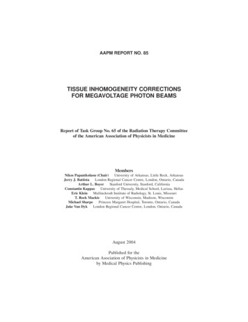
UCLA Abutment for Tissue LevelImplantProsthetic instruments needed
UCLA Abutment for Tissue LevelImplantFirmly insert the head of the HexDriver into the Thumbwheel
UCLA Abutment for Tissue LevelImplantRemove cover screwfrom implantAssemble screw driver with ITI Adapter (thumb-wheel / adapter)Insert assembled screw driver intocover screw and turn counter clockwise
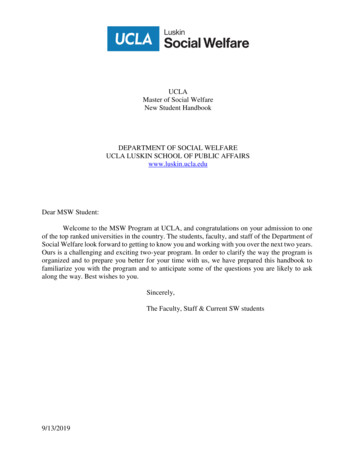
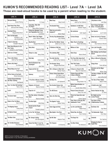
UCLA Abutment for Tissue LevelImplantOverhead view on impression transfer shows the centerscrew within the transferThe screw can spin separately from the impression copingSide view of impressiontransferMale octagon at the base of theimpression transfer matches thefemale octagon within the implant
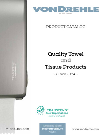
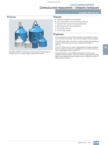
UCLA Abutment for Tissue LevelImplantUse driver assembly to tightenscrew clockwise with lightfinger pressureInsert screw into impression copingInsert the impression transfer intoimplant and rotate until male octagonof the transfer is aligned with femaleoctagon of the implant and transfer
UCLA Abutment for Tissue LevelImplantRemove screwdriverassemblyApply wax to the top of theimpression transfer to sealscrew access.
UCLA Abutment for Tissue LevelImplantInject impression material around theimpression transfer
UCLA Abutment for Tissue LevelImplantInsert tray with impression materialSeat impression tocapture dental arch
UCLA Abutment for Tissue LevelImplantRemove the impression from themouth when material has set
UCLA Abutment for Tissue LevelImplantUse a sharp instrumentto remove the wax fromthe impression transferRemove impressiontransfer from implant
UCLA Abutment for Tissue LevelImplantInsert cover screwback into implantCover screw in place
UCLA Abutment for Tissue LevelImplantInsert impression transfer intoanalog matching the respectiveoctagons and turn fixationscrew clockwise with fingerpressureInsert transfer/analogassembly into impression
UCLA Abutment for Tissue LevelImplantMake sure to align the flats within therubber of the impression with the flats onthe implant level impression copingImpression transfer/analoginside impression
UCLA Abutment for Tissue LevelImplantApply soft tissue replica materialaround implant level analogPour dental Straight into impression
UCLA Abutment for Tissue LevelImplantRemove model from impressionand loosen the fixation screw ofthe impression transfer by turningscrew driver counter clockwiseRemove impression transferfrom analog
UCLA Abutment for Tissue LevelImplantInsert screw driver assemblyinto fixation screw in theUCLA abutmentInsert abutment into implant level analog and alignthe male octagon of the abutment with the femaleoctagon of the implant level analog. Turn thefixation screw within the abutment clockwise (theabutment will remain stationary.)
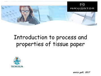
UCLA Abutment for Tissue LevelImplantCreate a wax up of the desired shapeof the abutment by subtracting oradding to the plastic of the UCLAabutmentCompleted custom castabutment made from the wax upof the UCLA abutment
UCLA Abutment for Tissue LevelImplantApply a seal to the top ofthe custom cast UCLAabutmentWax up the form of the undercastingover the completed custom cast UCLAabutment
UCLA Abutment for Tissue LevelImplantCast wax up using a conventionaltechnique and insert it in thecasting on the stone modelBuild and fire theCeramic in the usualmannerCeramiccrown onmodel
UCLA Abutment for Tissue LevelImplantUse the screw driver assemblyto insert the abutmentSeparate the screw driverassembly from the hexdriver
UCLA Abutment for Tissue LevelImplantInsert driver into the abutment screw andturn torque ratchet clockwise until torqueof 30 Ncm is reached and the head of theratchet releasesInsert the hex driver withinthe 30Ncm torque ratchet
UCLA Abutment for Tissue LevelImplantCement restoration onabutment
UCLA Abutment for Tissue Level Implant. Overhead view on impression transfer shows the center screw within the transfer . The screw can spin separately from the impression coping. Side view of impression. transfer. Male octagon at the base of the impression transfer match