Transcription
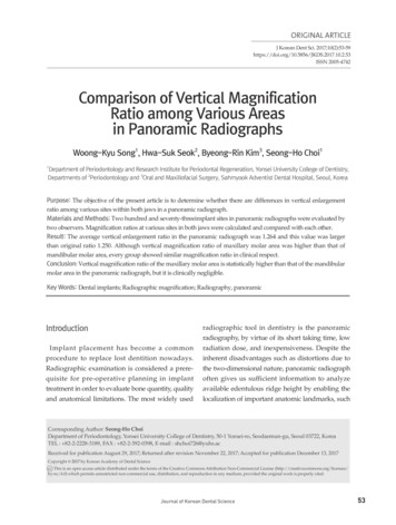
ORIGINAL ARTICLEJ Korean Dent Sci. 10.2.53ISSN 2005-4742Comparison of Vertical MagnificationRatio among Various Areasin Panoramic RadiographsWoong-Kyu Song1, Hwa-Suk Seok2, Byeong-Rin Kim3, Seong-Ho Choi11Department of Periodontology and Research Institute for Periodontal Regeneration, Yonsei University College of Dentistry,Departments of 2Periodontology and 3Oral and Maxillofacial Surgery, Sahmyook Adventist Dental Hospital, Seoul, KoreaPurpose: The objective of the present article is to determine whether there are differences in vertical enlargementratio among various sites within both jaws in a panoramic radiograph.Materials and Methods: Two hundred and seventy-threeimplant sites in panoramic radiographs were evaluated bytwo observers. Magnification ratios at various sites in both jaws were calculated and compared with each other.Result: The average vertical enlargement ratio in the panoramic radiograph was 1.264 and this value was largerthan original ratio 1.250. Although vertical magnification ratio of maxillary molar area was higher than that ofmandibular molar area, every group showed similar magnification ratio in clinical respect.Conclusion: Vertical magnification ratio of the maxillary molar area is statistically higher than that of the mandibularmolar area in the panoramic radiograph, but it is clinically negligible.Key Words: Dental implants; Radiographic magnification; Radiography, panoramicIntroductionImplant placement has become a commonprocedure to replace lost dentition nowadays.Radiographic examination is considered a prere quisite for pre-operative planning in implanttreatment in order to evaluate bone quantity, qualityand anatomical limitations. The most widely usedradiographic tool in dentistry is the panoramicradiography, by virtue of its short taking time, lowradiation dose, and inexpensiveness. Despite theinherent disadvantages such as distortions due tothe two-dimensional nature, panoramic radiographoften gives us sufficient information to analyzeavailable edentulous ridge height by enabling thelocalization of important anatomic landmarks, suchCorresponding Author: Seong-Ho ChoiDepartment of Periodontology, Yonsei University College of Dentistry, 50-1 Yonsei-ro, Seodaemun-gu, Seoul 03722, KoreaTEL : 82-2-2228-3189, FAX : 82-2-392-0398, E-mail : shchoi726@yuhs.acReceived for publication August 29, 2017; Returned after revision November 22, 2017; Accepted for publication December 13, 2017Copyright 2017 by Korean Academy of Dental Sciencecc This is an open access article distributed under the terms of the Creative Commons Attribution Non-Commercial License (http://creativecommons.org/licenses/by-nc/4.0) which permits unrestricted non-commercial use, distribution, and reproduction in any medium, provided the original work is properly cited.Journal of Korean Dental Science53
Woong-Kyu Song, et al: Comparison of Vertical Magnification Ratio among Various Areas in Panoramic Radiographsas mandibular canal and sinus floor.Vazquez et al.1) stated that panoramic radiographicexamination could be a standard radiographicexamination, especially for implants installed inthe posterior segment of the lower jaw, and mostpatients might not benefit from more extensiveimaging techniques that impart a higher radiationdosage. Other authors demonstrated that forsimple cases with a wide residual ridge and ampleridge height, clinical examination and panoramic/periapical radiography is sufficient2-4). On the otherhand, others claimed that taking only panoramicradiography may not be sufficient enough, insistingthe need for additional diagnostic tools, such asmultislice or cone-beam computed tomography(CT or CBCT), mainly because of the distortion,overlapping of anatomic landmarks and lowreproducibility of the image1,2,5-7).In order to verify the reliability of panoramic radio graph in implant treatment planning, especiallywhen determining size of the implant, it is essentialthat we are aware of the extent of image distortiondepending on locations within both jaws. Therefore,the aim of this study is to determine whether thereare differences in vertical enlargement ratio amongvarious sites within both jaws in a panoramic view.Materials and Methods1. Patient and Radiograph SelectionOne hundred and fifty-three patients treatedwith implants in the Sahmyook Adventist DentalHospital, Seoul, Korea were included in this study.Two hundred and seventy-three implant sites wereevaluated from the panoramic radiographs takenbetween July 2008 and April 2014.The radiographic images were taken by a digi talpanorama (ORTHOPHOS-XG5; SIRONA, Ben sheim, Germany). The manufacturer’s list includedthe magnification factor for this panoramic imageas 1.25. The images were viewed in the imagingsoftware (π-view STAR; Infinitt Healthcare, Seoul,54Korea) and in this program implant (R-line; Camlog,Stuttgart, Germany) (Superline/Implantium; Den tium, Seoul, Korea) length was calculated.The inclusion/exclusion criteria were like thefollowings. All included subjects were older than18 years and only premolar and molar areas wereinvestigated. The panoramic images should be clearso that implant margin can be distinguished. Onlysymmetric images were included. To calculate exactmagnification ratio, excessively angulated implantsthat did not show clear thread line were excluded.Images with absence of adjacent tooth for thereference were excluded as well.2. Implant Height Measurement in the RadiographicViewSubject was divided into 4 groups (Table 1). Thelengths of implants shown on post-surgical digitalpanoramic radiographs were calculated from thecoronal surface of cover screw to the implant tip.Implants made by Camlog have abutment of flatcoronal surface so in the measurements of Camlogimplant, abutment length was either included ornot, which did not appear to affect the accuracy ofthe measurements (Fig. 1). For more consistent andaccurate measurement, constant magnification rate(200%) was applied to each panoramic image.Implant length measurements were conductedtwice by two respective observers, so total numberwas 4 times of actual implant numbers. Eachparticipant did analysis twice with 1-week intervaland measured images were saved as jpeg file.Table 1. Classfication of the groups according the the eMnPMMnMMxPM: maxillary premolar, MxM: maxillary molar, MnPM:mandibular premolar, MnM: mandibular premolar areas.J Korean Dent Sci 2017;10(2):53-59
Woong-Kyu Song, et al: Comparison of Vertical Magnification Ratio among Various Areas in Panoramic Radiographs3. Calculation of Magnification RatioThe lengths of actual implant fixture and thosemeasured from the radiographic image werecompared and vertical magnification ratios werecalculated according to the following (Fig. 2).Implant enlargement ratio measured implantlength (mm)/actual implant length (mm)4. Statistical AnalysisData were exported to a statistical program(IBM SPSS ver. 22.0; IBM Co., Armonk, NY, USA)for the calculation of each group’s average andstandard deviation (SD) of the magnificationfactor. One sample t-test was performed for thecomparison of the magnification ratio obtainedfrom the measurements and that suggested by themanufacturer (1.25). Besides, group comparisonwas performed by one-way ANOVA or unpairedt-test. The statistical significance level of P 0.05 wasused. Interobserver and intraobserver reliabilities21.42 mm14.47 mmA12.92 mmCBFig. 1. Radiographic measurement of implant height in thepanoramic view. (A) Camlog implant fixture with abutment.(B) Camlog implant fixture with cover screw. (C) Dentium(Implantium) implant fixture with cover screw.ABFig. 2. Clinical measurement of implant height by vernier calipers. (A) Camlog implant. (B) Dentium implant.J Korean Dent Sci 2017;10(2):53-5955
Woong-Kyu Song, et al: Comparison of Vertical Magnification Ratio among Various Areas in Panoramic Radiographswere calculated by intra-class correlation coefficient(ICC).Result1. Distribution of the Implant SitesDistribution of the implant sites are shown in theTable 2 and Fig. 3. According to the implant sitesfour groups were defined as maxillary premolar(MxPM), maxillary molar (MxM), mandibularpremolar (MnPM), and mandibular molar (MnM)groups. MnPM group showed the lowest numberof implant sites as 19, and other sites the numberwere over 30.Table 2. Descriptive statistics of magnification ratio in the fourgroupsNumberMean SDMin MaxMxPMArea331.267 0.0231.200 1.313MxM1341.268 0.0211.191 1.315191.262 0.0231.209 1.296MnM871.256 0.0241.197 1.319Total2731.264 0.0231.191 1.319MnPMSD: standard deviation, Min: minimum, Max: maximum, MxPM:2. Comparison with Original Magnification RatioAverage magnification ratio of total area was 1.264(SD 0.023, n 273), and this value was statisticallydifferent with original ratio 1.250. Also other groupsshowed statistically different with original ratio.MxM area’s ratio was the highest value.3. Group ComparisonMxPM group showed mean enlargement ratio1.267 (SD 0.023, n 33), MxM group showed1.268 (SD 0.021, n 134), MnPM group showed1.262 (SD 0.023, n 19), and MnM group showed1.256 (SD 0.024, n 87). Only between MxM andMnM groups, there was a statistically significantdifference. Other groups didn’t show statisticallysignificant difference (Fig. 4).4. ICCICC value was 0.995 among two observer’s 1st,2nd measurement. Therefore, interobserver andintraobserver reliability can be considered proper.DiscussionIn this study, we calculated magnification ratiosfrom four different sites, in respective premolar andmaxillary premolar, MxM: maxillary molar, MnPM: mandibularpremolar, MnM: mandibular premolar areas.1.28001.3300*95% CI 400MxPM1.1700MnPMMnMGroupMxPMMxMMnPMMnMGroupFig. 3. Distribution of magnification ratio in the four areas.MxPM: maxillary premolar, MxM: maxillary molar, MnPM:mandibular premolar, MnM: mandibular premolar areas.56MxMFig. 4. Each group comparison (95% confidence interval [CI] forthe mean) of the enlargement ratio. MxPM: maxillary premolar,MxM: maxillary molar, MnPM: mandibular premolar, MnM:mandibular premolar areas. *Statistical difference betweengroups.J Korean Dent Sci 2017;10(2):53-59
Woong-Kyu Song, et al: Comparison of Vertical Magnification Ratio among Various Areas in Panoramic Radiographsmolar areas in maxilla and mandible, using implantas a reference material in panoramic radiographs.This study revealed from a statistical point of viewthat vertical magnification ratio of the MxM areawas significantly higher than that of the MnM areain panoramic radiographs.Panoramic radiography shows a magnifying effectduring the image formation due to the distancebetween the radiation source, the object and theimage receptor8). Whilst the particular anatomicalarea of a patient’s head located within the imagelayer would appear without distortion on theradiograph, the positional discrepancy betweenthe jaw and the image layer produces variousmagnification ratios depending on locations withina jaw.Magnification factor in panoramic radiograph canbe calculated in two dimensions-horizontal andvertical factors. Many previous literatures describedthat vertical magnification factor is reliable andconstant when patient is in upright position,whereas horizontal magnification has wide vari ation 5,9-12). However, previous studies showedcon flicting results on vertical magnification ratedifferences among various sites. Gomez-Roman etal.13) calculated magnification ratios using implantsand reported vertical magnification ratios werehigher in the maxilla than in the mandible. Kim etal.14) measured vertical enlargement of implantsalready placed in the oral cavity, and found atendency of slightly greater enlargement in maxillathan in the mandible.In contrast, several studies revealed that there wasno difference in vertical magnifications regardlessof the locations in the oral cavity. Schropp et al.9)found that there were no vertical magnificationratio differences between maxilla and mandible, oramong variable positions in the same arch. Otherstudies also showed no differences among variablepositions in the mandible4,12).In our study, similar magnification ratios wereshown in all areas. Although vertical magnificationratio in the MxM area was statistically higher thanthat in the MnM area, this difference was only0.012. Therefore it is difficult to state its clinicalsignificance. We measured vertical magnificationratio in the premolar and molar areas, and totalmean vertical magnification ratio was 1.264, withranges from 1.191 to 1.319. Considering that themagnification ratio given by manufacturer is 1.25,one should always be cautious when determiningsize of the implant using only the panoramicradiograph and the magnification ratio suggestedby the manufacturer because of its variation.Many studies used various reference markers,such as metal ball, metal bar, gutta percha andim plant, for analyzing magnification ratio9,11,15,16).The advantages of metal ball are its symmetricalshape and easy to measure. However, informationon the marker’s angulation cannot be obtained.Gutta percha has a rope shape but it is too thin formeasuring angulation or height. Autoclavable metalbar is convenient for the measurement and easy toanalyze angulation with9,17,18). Implant used in thisstudy can be a good reference material becauseof the accurate height manufactured by delicatemachine, Their cylindrical shape is also favorablestructure for analyzing angulation.In the present study, the number of premolarsites was too small compared to other sites. Manypanoramic images were excluded because of theinadequate angulation. More data from premolarsites are needed to obtain reliable result. Moreover,because the thickness and shape of image layer ofpanoramic x-ray machine may be variable accor ding to the manufacturer, it is difficult to apply thepresent findings to anonymous system. Additionalresearch is recommended for other company’smachines.ConclusionWithin the limit of the study, vertical magnificationratios were similar among various tooth sites inJ Korean Dent Sci 2017;10(2):53-5957
Woong-Kyu Song, et al: Comparison of Vertical Magnification Ratio among Various Areas in Panoramic Radiographsthe panoramic radiography. Although verticalenlargement ratio of the MxM area was statisticallyhigher than that of the MnM area, it is consideredclinically negligible.Radiographic evaluation of mandibular posteriorimplant sites: correlation between panoramic andtomographic determinations. Clin Oral ImplantsRes. 1996; 7: 354-9.8. Ogawa K, Langlais RP, McDavid WD, Noujeim M,Seki K, Okano T, Yamakawa T, Sue T. DevelopmentConflict of Interestof a new dental panoramic radiographic systemNo potential conflict of interest relevant to thisarticle was reported.based on a tomosynthesis method. DentomaxillofacRadiol. 2010; 39: 47-53.9. Schropp L, Stavropoulos A, Gotfredsen E, WenzelA. Calibration of radiographs by a reference metalReferencesball affects preoperative selection of implant size.1. Vazquez L, Saulacic N, Belser U, BernardJP. Efficacy of panoramic radiographs in the10. Frei C, Buser D, Dula K. Study on the necessity forpreoperative planning of posterior mandibularcross-section imaging of the posterior mandible forimplants: a prospective clinical study of 1527treatment planning of standard cases in implantconsecutively treated patients. Clin Oral Implantsdentistry. Clin Oral Implants Res. 2004; 15: 490-7.Res. 2008; 19: 81-5.11. Ladeira DB, Cruz AD, Almeida SM, Bóscolo FN.2. Dula K, Mini R, van der Stelt PF, Buser D. TheEvaluation of the panoramic image formation inradiographic assessment of implant patients:different anatomic positions. Braz Dent J. 2010; 21:decision-making criteria. Int J Oral Maxillofac458-62.Implants. 2001; 16: 80-9.12. Catić A, Celebić A, Valentić-Peruzović M, Catović A,3. Allen F, Smith DG. An assessment of the accuracyJerolimov V, Muretić I. Evaluation of the precisionof ridge-mapping in planning implant therapy forof dimensional measurements of the mandible onthe anterior maxilla. Clin Oral Implants Res. 2000;panoramic radiographs. Oral Surg Oral Med Oral11: 34-8.Pathol Oral Radiol Endod. 1998; 86: 242-8.4. Reddy MS, Mayfield-Donahoo T, Vanderven13. Gomez-Roman G, Lukas D, Beniashvili R,FJ, Jeffcoat MK. A comparison of the diagnosticSchulte W. Area-dependent enlargement ratiosadvantages of panoramic radiography andof panoramic tomography on orthograde patientcomputed tomography scanning for placement ofpositioning and its significance for implantroot form dental implants. Clin Oral Implants Res.dentistry. Int J Oral Maxillofac Implants. 1999; 14:1994; 5: 229-38.248-57.5. BouSerhal C, Jacobs R, Quirynen M, van14. Kim YK, Park JY, Kim SG, Kim JS, Kim JD.Steenberghe D. Imaging technique selection for theMagnification rate of digital panoramic radio preoperative planning of oral implants: a review ofgraphs and its effectiveness for pre-operativethe literature. Clin Implant Dent Relat Res. 2002; 4:assessment of dental implants. Dentomaxillofac156-72.Radiol. 2011; 40: 76-83.6. Lindh C, Petersson A, Klinge B. Measurements15. Yim JH, Ryu DM, Lee BS, Kwon YD. Analysis ofof distances related to the mandibular canal indigitalized panorama and cone beam computedradiographs. Clin Oral Implants Res. 1995; 6: 96-tomographic image distortion for the diagnosis of103.dental implant surgery. J Craniofac Surg. 2011; 22:7. Bolin A, Eliasson S, von Beetzen M, Jansson L.58Clin Oral Investig. 2009; 13: 375-81.669-73.J Korean Dent Sci 2017;10(2):53-59
Woong-Kyu Song, et al: Comparison of Vertical Magnification Ratio among Various Areas in Panoramic Radiographs16. Park JB. The evaluation of digital panoramicradiographs: the effect of shape and position ofradiographs taken for implant dentistry in theedentulous mandibles. Oral Surg Oral Med Oraldaily practice. Med Oral Patol Oral Cir Bucal. 2010;Pathol Oral Radiol Endod. 1997; 84: 430-5.15: e663-6.18. Takeshita F, Tokoshima T, Suetsugu T. A stent for17. Batenburg RH, Stellingsma K, Raghoebar GM,Vissink A. Bone height measurements on panoramicpresurgical evaluation of implant placement. JProsthet Dent. 1997; 77: 36-8.J Korean Dent Sci 2017;10(2):53-5959
Clinical measurement of implant height by vernier calipers. (A) Camlog implant. (B) Dentium implant. AB AB C 14.47 mm 12.92 mm 21.42 mmmm Fig. 1. Radiographic measurement of implant height in the panoramic view. (A) Camlog implant fixture with abutment. (B) Camlog implant fixture with cover screw. (C) Dentium (Implantium) implant fixture with .