Transcription
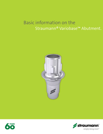
Technical InformationStraumann Screw-retained AbutmentsBasic Information
Contents1.2.3.General information 11.1 Purpose of this guide 11.2 Introduction to Straumann Screw-retained Abutments 21.3 Straumann Screw-retained abutment – overview 3Soft tissue management 52.1 Soft tissue management solutions 52.2 Healing abutments that suit CrossFit Screw-retained abutments 62.3 Overview of Consistent Emergence Profiles for TorcFit Screw-retained abutments 7Prosthetics and lab procedures 93.1 Impression Taking 93.2 Plan abutments for RB/WB Screw-retained Abutments for intra- and extra-oral planning 4.113.3 Single-unit restoration 133.4 Multi-unit restoration 193.5 Edentulous restoration: Fixed option with immediate temporary restoration 263.6 Edentulous restoration: removable restoration 31Aids and instruments 334.1 SCS Screwdriver 334.2 Polishing Aid 334.3 Ratchet and Torque Control Device 344.4 Assembling the Ratchet and the Torque Control Device 364.5 Tightening an abutment to 35 Ncm 385.About cleaning and sterilization 406.Product reference list 416.1 System overview 416.2 Auxiliaries and instruments 45Important guidelines 467.
1. General informationCrossFit TorcFit 1.1 Purpose of this guideThis guide was created for dental technicians and dentists working with the Straumann Bone levelScrew-retained abutments for designing screw-retained customized prosthetic reconstructions, such ascrowns, bridges or over-dentures. It provides complementary step-by-step information on working with theStraumann Screw-retained abutments.Failure to follow the procedures outlined in these instructions may harm the patient and/or lead to any orall of the following complications:ѹ Aspiration or swallowing of a componentѹ Breakageѹ InfectionNote:Implant-borne superstructures require optimal oral hygiene from the patient. This must be considered byall involved parties when planning and designing the restoration.All products shown in this guide are for single use only if not indicated otherwise on the respective productlabel.Consult the brochure:Straumann Dental Implant System, Basic Information, for information on indications and contraindications ofStraumann implants such as the required minimum number of implants, implant type, diameter and loadingprotocols.USLIT.1194CALIT.1194Straumann BLX Implant System, Basic Information, for information on indications and contraindications ofStraumann implants such as the required minimum number of implants, implant type, diameter and loadingprotocols.USLIT.1205CALIT.1205Straumann Bone Level Prosthetics ProceduresUSLIT.232CALIT.232Straumann Pro Arch Basic InformationNAMLIT.1060Consult the Instructions for use:Straumann Titanium Abutments and Temporary Abutments/Copingsifu.straumann.com1
CrossFit 1.2 Introduction to Straumann Screw-retained AbutmentsTorcFit BLX (TorcFit )Intended useѹ Screw-retained multi-unit as well as single-unit restorations onabutment-levelѹ Full-arch restorations on abutment-level, screw-retained as well asremovableSleek design and clear portfolioѹ Same abutment-restoration connection design for all diameters,angulations and implant connections allow a streamlined portfolio oftertiary componentsѹ Abutment angulations of 0 , 17 and 30 ѹ Abutment design allows multi-unit as well as single-unit restorationsѹ Sterile packed for immediate useBL/BLT (CrossFit )ѹ Large variety of gingiva heights availableType ACrossFit :Type BTwo types of Screw-retained abutments areavailable, type A and type B. This enables the axisto be corrected in 8 different alignments (in 45 graduations).Angle between flat sidesNC 3.5 mm straight abutmentsNC 4.6 mm straight abutmentsNC 4.6 mm angled abutmentsGH 2.5*/3.5/4.5/5.5 mmRC 4.6 mm straight abutmentsGH 1.5/2.5/3.5 mmRC 4.6 mm angled abutmentsGH 2.5*/3.5/4.5/5.5 mmRB/WB 4.6 mm straight abutmentsGH 1.5/2.5/3.5/4.5 mmRB/WB 4.6 mm angled abutmentsGH 3.5/4.5/5.5 mm*GH 2.5 not available for 30 angled abutments2GH 1.5/2.5/3.5 mmAngle to the flat wallSingle-unitrestorationMulti-unitrestorations (incisor topremolar region)Multi-unitrestorations (molar region)YesYesNoNo limitation
CrossFit TorcFit 1.3 Straumann Screw-retained abutment – overviewNarrow CrossFit Regular CrossFit 4.6TorcFit RB & WBDiameter3.54.6Angulation0 0 CodingBlueYellowGreyMagentaAbutment height1.8 mm1.8 mm1.8 mm1.8 mmAngle of Abutmentrestoration connection22 22 22 22 Gingiva heights1.5 mm2.5 mm3.5 mm1.5 mm2.5 mm3.5 mm17 30 0 2.5 mm (17 only)3.5 mm4.5 mm5.5 mm1.5 mm2.5 mm3.5 mm4.617 30 2.5 mm (17 only)3.5 mm4.5 mm5.5 mm0 1.5 mm2.5 mm3.5 mm4.5 mm17 30 3.5 mm4.5 mm5.5 mmImpression components**impression components are available as non-engaging (for bridges) and engaging components (for crowns)Non engagingAbutment screwsStraight abutmentsEngagingAngled abutmentsAngledabutmentsIntegratedin one-pieceabutmentIntegrated in one-piece abutmentTightening forceabutment screwStraightabutments35 NcmOcclusal screwsTightening force occlusalscrew15 NcmLab processing screwsLab polishing aidAnalogs andrepositionable analogs3
CrossFit TorcFit 3.5 mmEngaging(Crown)Temporary TAN coping024.0021Titanium Coping023.2747Gold Coping023.2751Non-engaging(Bridges / Bars)Temporary TAN Coping,Bridge024.0022Titanium Coping, Bridge023.2749Titanium Coping, Bar023.2750Gold Coping, Bridge023.2752Gold Coping, Bar023.2753 4.6 mmEngaging(Crown)Temporary TAN coping024.0023Titanium Coping023.4747Gold Coping023.4753Non-engaging(Bridges / Bars)Temporary TANCoping, Bridge024.0024Coping, Ti, Bridge023.4751Coping, Ti, Bar023.4752Coping, Gold,Bridge023.4754Occlusal Screw023.47634Coping, Gold, Bar023.4755Variobase forBridge/Bar Cylindrical023.0028Burn-out Coping,for Variobase for Bridge/BarCylindrical Coping023.0032
2. Soft tissue managementCrossFit TorcFit The Straumann Bone Level Implant lines put a strong emphasis on esthetic considerations. They offer tailor-made solutionsthat allow for natural soft tissue shaping and maintenance in all indications. A versatile portfolio of healing and temporaryabutments is available, including customizable products made of polymer for easy and fast processing.2.1 Soft tissue management solutionsHealing AbutmentPrefabricated healingabutment (titanium)Temporary AbutmentCustomizable healingabutment (polymer)PMMA with titaniumalloy inlay--Titanium alloy (TAN)BL/BLT (CrossFit )BLX (TorcFit )Note: Do not use for longer than 6 months.5
CrossFit 2.2 Healing abutments that suit CrossFit Screw-retained abutmentsPlatformNCScrew-retained AbutmentTypeMaterialTANTANTANTANAngle0 0 17 30 (mm)3.54.64.6GH (mm)1.5GH (mm)2.0 .53.54.55.53.54.84.8TypeConical Healing AbutmentPlatformRCScrew-retained AbutmentTypeMaterialAngle (mm)TANTANTAN0 17 30 4.64.6GH (mm)1.52.53.5GH (mm)2.04.06.0 (mm)2.53.54.64.53.54.05.05.0TypeConical Healing Abutment65.54.55.5
TorcFit 2.3 Overview of Consistent Emergence Profiles for TorcFit Screw-retained abutmentsWhich healing abutments suit which final abutment?CrownsHealing Abutmentsfor CrownTemporary Abutmentsfor CrownFinal Abutments064.4212S / 064.4213S064.4372062.4722S064.4214S / 064.4215S064.4373062.4723S064.4216S / 064.4217S064.4374062.4724SGH 1.5 mmGH 2.5 mmGHGingiva HeightGingiva HeightGH 3.5 mmGHFinal Abutment 4.5 mmGHGingiva Height7
TorcFit How to match fitting TorcFit componentsRB/WB Screw-ret. Abut.straight, Ø 4.6mm, GH 2.5mm, TAN062.4723SDimensions on componentsXXXXXLabelYYYY-MM-DDLabel textRB/WB Screw-ret. Abut.062.4723SGH 2.5 mmstraight, Ø 4.6mm, GH 2.5mm, TANYYYY-MM-DDstraight, Ø 4.6mm, GH 2.5mm, TANRB/WB Screw-ret. Abut. 4.5 mmDE RB/WB Verschraubtes Sekundärteilgerade, Ø 4.6mm, GH 2.5mm, TANFR RB/WB Pilier transvissédroit, Ø 4.6mm, GH 2.5mm, TANIT RB/WB Componente secondaria avvitatadiritta, Ø 4.6mm, GH 2.5mm, TANPT RB/WB Pilar aparafusadoreto, Ø 4.6mm, GH 2.5mm, TANES RB/WB Pilar atornilladorecto, Ø 4.6mm, GH 2.5mm, TANZZZZZZZZZZ062.4723SXXXXXYYYY-MM-DDRB/WB Screw-ret. Abut.straight, 4.6 mm,GH 2.5 mm, WB Temporary 4.5 mmAbutment, for crown,GH 2.5 mm 4.5 mm, GH 2.5 mm, TAN 5 mmRB/WB Healing Abutment*,GH 2.5 mmCrown, 5 mm, GH2.5 mm, AH 2 mm, Ti* Healing abutments anticipate the final crown, therefore, they have a larger nominal diameter than the final abutments.8
Prosthetic procedure3. Prosthetics and lab proceduresCrossFit TorcFit 3.1 Impression TakingPreparationGeneral: It is recommended to take the impression on the level that thefinal restoration is planned on to ensure proper fit of the temporary andfinal restoration:ѹ Abutment-level impression for restoration on abutment levelѹ Implant-level impression for restoration on implant level3.1.1 Impression-taking on abutment levelOpen-tray impressionMake sure the abutments are torqued down with 35 Ncm.Place the open-tray impression posts onto the abutments and fix themwith the screw.Ensure correct positioning of the impression posts on the abutments.For single-unit restoration use the impression components with the engagingfeature, for multi-unit restorations use the impression components withthe non-engaging feature.Take the impression using an elastomeric impression material.Forward the impression and all corresponding impression components tothe dental lab.Caution: unscrew the open-tray impression posts from Implants/abutmentsbefore releasing the impression material from the patient/model.Note: Open-tray impression procedure requires a custom-made tray withperforations. Impression posts are intended for single use only to ensureoptimal fit and precise impression taking for each patient.Closed-tray impressionMake sure the abutments are torqued down with 35 Ncm.Place the closed-tray impression posts onto the abutments and fix themwith the screw.Ensure correct positioning of the impression posts on the abutments.Position the positioning cap onto the impression post.9
Prosthetic procedureCrossFit For single-unit restoration use the impression components with theengaging feature, for multi-unit restorations use the impressioncomponents with the non-engaging feature.Take the impression using an elastomeric impression material.Forward the impression and all corresponding impression components tothe dental lab.3.1.2 Impression-taking on implant levelIn case all implants are placed straight, there is the option of taking animplant-level impression (for instructions see chapter 6. Impression takingfrom BL Prosthetics Procedures (USLIT.232 / CALIT.232).10CrossFit TorcFit TorcFit
Prosthetic procedureTorcFit 3.2 Plan abutments for RB/WB Screw-retained Abutmentsfor intra- and extra-oral planningCharacteristicsSimpleѹ Color-coded and easily readableѹ Easy handling with the integrated holding pinѹ All gingiva heights marked on each abutmentReliableѹ Plan abutments fabricated of sterilizable polymer materialDesigned to facilitate Pro Arch restoration planningѹ 0 , 17 and 30 abutments to cover implant divergencesѹ Indication of occlusal screw channel directionѹ Possibility to cut the pin for easier placement in posterior region of themouthNotes:ѹ After intraoral use clean and sterilize the Plan abutments as describedin the IFU (702897 - Instructions for use: Straumann prostheticplanning and placement tools)0 17 30 ѹ Replace non-functional Plan abutments.ѹ If you decide to cut the pin, it is recommended to polish the end. Do notcut the pin shorter than the last groove.ѹ For extra-oral use: while these plan abutments were optimized for intraoral use, slight vertical movements are possible when used extra-orally(in implant analog). Make sure the plan abutments are correctly seated.3.2.1 For single-unit restorationsPlace the Plan abutment on the implant (intra-oral use) or implant analog(extra-oral use).This will aid in checking dimensions (laser marks on Plan abutments indicategingiva height), axial alignment and occlusal screw axis of the potentialrestoration.11
Prosthetic procedureTorcFit 3.2.2 For multiple-unit restorationsPlace the Plan abutments on the implants (intra-oral use) or implant analog(extra-oral use).This will aid in checking dimensions (laser marks on Plan abutments indicategingiva height), axial alignment and occlusal screw axis of the potentialrestoration.A clear duplicate of the provisional may be used to check the alignment ofthe different occlusal screw axis.3.2.3 Identification of the gingiva heights marked on the plan abutments and corresponding RB/WB Screw-retained AbutmentsGH 4.5 mmGH 3.5 mmGH 2.5 mmGH 1.5 mmStraight062.4722S062.4724S062.4725SGH 5.5 mmGH 4.5 mmGH 3.5 mmGH 5.5 mmGH 4.5 mmGH 3.5 mm17 12062.4723S062.4733S 062.4734S 062.4735S30 062.4743S 062.4744S062.4745S
Lab procedureProsthetic procedureCrossFit TorcFit 3.3 Single-unit restorationUsing protective capsMount the protective cap onto the abutment and hand-tighten the screwswith the SCS screwdriver.Note: Do not keep protective caps in the patient’s mouth for longer than180 days.Protective caps are available in different shapes and heights, to be chosenaccording the patient anatomical situation and desired outcome.Temporary restorationUsing temporary TAN copings or titanium copingsBased on the dental impression prepare the master cast using the appropriateanalog.Temporary TAN CopingTitanium Coping13
Lab procedureProsthetic procedureCrossFit Place the coping with engaging features onto the analog.Modify the coping according to the required length.Optional: Sandblast the coping and coat it with opaquer to avoid Titanium/TAN shining through.Cover the screw channel with absorbent cotton or gutta-percha and sealthe screw channel.Warning: do not sandblast the inner configuration and connection portionsof the copings.Use a standard procedure to create the temporary crown.Remove excess material, re-open the screw channel of the coping andfinalize the temporary crown.Finalized crown14TorcFit
Lab procedureProsthetic procedureCrossFit TorcFit Remove protective cap from the abutment in the patient’s mouth.Insert the provisional into the patient’s mouth with a torque of 15 Ncm.Cover the screw channel with absorbent cotton or gutta-percha and sealthe screw channel.Note: Keep the temporary restoration out of occlusion.Final restorationExample using gold copingsѹ For this procedure use the gold coping with the engaging feature.Fix the corresponding analog into the impression material from thepatient’s situation.Note: Ensure that the color code of the analog corresponds to the color codeof the impression components.Fabricate the master cast using standard procedure (for instructions seechapter 6. Impression taking from BL Prosthetics Procedures (USLIT.232).Model a full anatomic wax-up for optimal esthetic planning. Use thecorresponding gold copings or burn-out copings as a base for the wax-up.15
Lab procedureCrossFit Define the optimal shape of the restoration by making a silicone key overthe full wax-up.Place the gold coping on the analog and hand-tighten the occlusal screwusing the SCS screwdriver.Shorten the modeling aids to the height of the occlusal plane according tothe individual situation. Working with the modeling aid ensures a clean andsharp-edged finish of the screw channel.Fabricate the superstructure on the abutments using standard modelingprocedure.Make sure that the wax layer on the abutment is sufficiently thick (at least0.7 mm). Do not cover the delicate margin of the coping with wax.Check the spatial conditions before casting the crown framework with thesilicone key of the wax-up.Before investing the wax framework, make sure the framework istension-free.16TorcFit
Lab procedureCrossFit TorcFit Note: In order to avoid overflow of the cast-on alloy, clean the copingsthoroughly prior to investment (removal of wax particles and insulatingagents with a cotton pellet or brush moistened with alcohol).Ensure that there is no wax on the delicate margin.The use of investment materials for rapid heating methods (speedinvestment materials) is not recommended.When processing the investment material, follow the manufacturer’sinstructions. Strictly observe the recommended mixing ratio and preheatingtime.Make sure the screw channel and the internal configuration of the copingsare filled with investment material from the bottom to the top in order toavoid air bubbles (see pictures).Long-term success of the prosthetic work depends on the accurate fit ofthe restoration. The entire procedure will have to be repeated if castingerrors occur.17
Lab procedureProsthetic procedureCrossFit Invest the framework according to standard methods without using wettingagents.Cast and devest the framework using standard methods.Check for tension-free fitting on the master cast by applying the Sheffieldtest.Do an additional try-on of the tensionfree fit of the crown in the patient’smouth.Veneer the superstructure.Note: Alternatively, burn-out copings may be used.18TorcFit
Lab procedureProsthetic procedureCrossFit TorcFit 3.4 Multi-unit restorationUsing the protective capsMount the protective caps onto abutments and hand-tighten the screwswith the SCS screwdriver.Note: Do not keep protective caps in the patient’s mouth for longer than180 days.Protective caps are available in different shapes and heights, to be chosenaccording the patient anatomical situation and desired outcome.Temporary restorationUsing temporary TAN copings or Titanium copingsBased on the dental impression prepare the master cast using the appropriateanalogs.Temporary TAN CopingTitanium CopingPlace the copings with non-engaging features onto the analogs.Modify the copings according to the required length.Optional: Sandblast the copings and coat them with opaquer to avoid titanium/TAN shining through.Cover the screw channel with absorbent cotton or gutta-percha and sealthe screw channel.19
Lab procedureProsthetic procedureCrossFit Warning: do not sandblast the inner configuration and connection portionsof the copings.Use a standard lab procedure to create the temporary bridge.Remove any excess material, re-open the screw channels and finalize thetemporary bridge.Insert the temporary bridge into the patient’s mouth applying a 15 Ncmtorque.Cover the screw channels with absorbent cotton or gutta-percha and sealthe screw channel.Note: Keep the temporary restoration out of occlusion.20TorcFit
Lab procedureCrossFit TorcFit Final restorationFinal restoration using CADCAM systemFabricate the master cast using standard procedure (for instructions seechapter 6. Impression taking from BL Prosthetics Procedures (USLIT.232 /CALIT.232).In order to transfer the impression data into the CARES software useabutment-level scanbodies for the screw-retained abutments.Hand-tighten the scanbodies onto the analogs in the dental model.Place the dental model in the scanner and follow the scanning instructions.Design the framework in the software as needed.Transfer the final design to the milling facilities.21
Lab procedureCrossFit Veneer the custom-milled superstructure.In case you do not have access either to Straumann CARES or Createch,the final restoration can be prepared using standard procedure.Example using gold copingsѹ For this procedure non-engaging gold copings are used.Fix the corresponding analogs into the impression.Note: Ensure that the color code of the analogs corresponds with the colorcode of the impression components.Fabricate the master cast using standard procedure (for instructions seechapter 6. Impression taking from BL Prosthetics Procedures (USLIT.232 /CALIT.232).Model a full anatomic wax-up for optimal esthetic planning. Use thecorresponding gold copings or burn-out copings as a base for the wax-up.Define the optimal shape of the restoration by making a silicone key overthe full wax-up.22TorcFit
Lab procedureCrossFit TorcFit Place the gold copings on the analogs and hand-tighten the occlusal screwusing the SCS screwdriver.Shorten the modeling aids to the height of the occlusal plane according tothe individual situation. Working with the modeling aid ensures a clean andsharp-edged finish of the screw channel.Fabricate the superstructure on the abutments using standard modelingprocedures.Make sure that the wax layer on the abutment is sufficiently thick (at least0.7 mm). Do not cover the delicate margin of the coping with wax.Check the spatial conditions before casting the crown framework with thesilicone key of the wax-up.Before investing the wax framework make sure the framework is tensionfree.23
Lab procedureCrossFit Note: In order to avoid overflow of the cast-on alloy, clean the copingsthoroughly prior to investment (removal of wax particles and insulatingagents with a cotton pellet or brush moistened with alcohol).Ensure that there is no wax on the delicate margin.The use of investment materials for rapid heating methods (speed investmentmaterials) is not recommended.When processing the investment material, follow the manufacturer’sinstructions. Strictly observe the recommended mixing ratio and preheatingtime.Make sure the screw channel and the internal configuration of the copingsare filled with investment material from the bottom to the top in order toavoid air bubbles (see picture).Long-term success of the prosthetic work depends on the accurate fit ofthe restoration. The entire procedure will have to be repeated if castingerrors occur.Invest the framework using standard procedure without using wettingagents.Cast and devest the framework using standard procedure.Check for tension-free fitting on the master cast by applying the Sheffieldtest. If the bridge is not tension-free and wiggles, cut the bridge and resplinttension-free.24TorcFit
Lab procedureProsthetic procedureCrossFit TorcFit Do an additional try-on of the tensionfree fit of the bridge in thepatient’s mouth.Veneer the superstructure.Note: Alternatively, burn-out copings can be used.25
Lab procedureProsthetic procedureCrossFit 3.5 Edentulous restoration: Fixed option with immediate temporary restorationUsing protective capsMount the protective caps on the abutments and hand-tighten the screwswith the SCS screwdriver.Note: Do not keep protective caps in the patient’s mouth for longer than180 days.Protective caps are available in different shapes and heights, to be chosenaccording the patient anatomical situation and desired outcome.Temporary restorationUsing temporary TAN copings or titanium copingsѹ In this case the preparation of an immediate provisional in the dentallab is shown.Based on dental impression, prepare the master cast using standardprocedure.Based on the impression and bite registration, prepare the provisional denture.For the surgical procedure, prepare a duplicate of the provisional in clearacrylic material.Temporary TAN or titanium copings will represent the implant position andangulation in the acrylic guide.Note: For more detailed information on the surgical procedure, please seethe Straumann Pro Arch, Basic Information (NAMIT.1060).26Temporary TAN CopingTitanium CopingTorcFit
Lab procedureProsthetic procedureCrossFit TorcFit In the dental lab, prepare holes in the temporary denture according to thenumber of copings. Consider sufficient space for resin material.Check if there is sufficient space for the copings.In the patient’s mouth, connect the copings with the temporary prosthesisusing resin material and transfer to the dental lab for finalizing.27
Lab procedureCrossFit In the dental lab, finalize and polish the temporary restoration.Note: In order to protect the abutment configuration from resin flowing in,use the polishing aids.Final restoration: Screw-retained – CADCAM optionFabricate the master cast using standard procedure (for instructions seechapter 6. Impression taking from BL Prosthetics Procedures (USLIT.232 /CALIT.232).In order to transfer the impression data into the CARES software, useabutment-level scanbodies for the screw-retained abutments.Hand-tighten the scanbodies onto the analogs in the dental model.28TorcFit
Lab procedureCrossFit TorcFit Place the dental model in the scanner and follow the scanning instructions.Design the framework for screw-retained restorations in the software asneeded. Transfer the final design to the milling facility.Example of a Straumann CARES Advanced Fixed Bar on 4 implantsExample of a Straumann CARES Basic Fixed Bar on 4 implants29
Lab procedureCrossFit Veneer and finalize the custom-milled superstructure.CARES Advanced Fixed BarCARES Basic Fixed Bar30TorcFit
Lab procedureCrossFit TorcFit 3.6 Edentulous restoration: removable restorationUsing traditional Dolder barsFix the corresponding analogs into the impression.Note: Ensure that the color code of the analogs corresponds with the colorcode of the impression components.Fabricate the master cast using standard procedure (for instructions seechapter 6. Impression taking from BL Prosthetics Procedures (USLIT.232 /CALIT.232).Before placing the copings onto the master cast, we recommend mountingthe occlusal screw onto the SCS screwdriver. Place the bar copings onto themaster cast and hand-tighten with the occlusal screws.Fabricate a soldered or laser-welded titanium bar using standard procedure.Note: Use stabilization pins for the soldering of a gold bar.Remove the temporary restoration before inserting the final restoration.Clean the abutments thoroughly in the patient’s mouth.Check tension-free fit of the bar before tightening.31
Prosthetic procedureCrossFit Tighten the occlusal screw to 15 Ncm using the SCS screwdriver with theratchet and the torque control device.Note: For more detailed information on Straumann CARES Basic andAdvanced Fixed Bars, please refer to Basic Information on Screw-RetainedBars and Bridges (NAMLIT.1188).32TorcFit
4. Aids and instrumentsCrossFit TorcFit 4.1 SCS ScrewdriverThe SCS* screwdriver is used for the fixation of the prosthetic parts andhealing components. The star shape of the screwdriver tip connects to thetop of the healing components and abutment screw heads for safe pick-upand handling.*SCS S crew C arrying SystemSCS screwdriver for manual useArticle: extra short, short, longLengths: 15 mm, 21 mm, 27 mmArt. Nos.: 046.400, 046.401, 046.402Material: Stainless steel4.2 Polishing AidThe polishing aid is used during polishing and other lab procedures toprotect the abutment’s prosthetic connection and to establish a convenientfixation extension.Art. Nos.: 025.2920, 025.4920Material: Stainless steelNote: In the case of BLX, use an implant analog.33
CrossFit 4.3 Ratchet and Torque Control DeviceThe ratchet (Art. No. 046.119) is a two-part lever arm instrument with arotary knob for changing the direction of force. It is supplied with a serviceinstrument (Art. No. 046.108), which is used to loosen the headed screw. After loosening, the ratchet bolt can be removed from the body of the ratchet.The ratchet must be disassembled for cleaning and sterilization.To apply a certain torque when tightening a screw, use the ratchet togetherwith the torque control device (Art. No. 046.049) and the holding key (Art.No. 046.064).RatchetThe ratchet is used in combination with the torque control device to torquein all Straumann abutments and screws (it is the same ratchet used for placing Straumann implants manually).Note: The ratchet and service instrument are packaged together.looped endflared partnutdirectional arrowratchet disassembled34TorcFit
CrossFit TorcFit Torque control deviceConnected to the ratchet, the torque control device is used to measure the value of Ncm (Newton centimeter) applied when insertingStraumann abutments and screws.fluted endtorque scaletear dropService InstrumentThe Service Instrument is used to assemble and disassemble theratchet.Holding keyThe forked end of the holding key can be used to assemble and disassemble the ratchet. The pin can be used to stabilize drivers whenabutments and screws are placed (also used for implant placement).pinforked end35
CrossFit 4.4 Assembling the Ratchet and the Torque Control DeviceStep 1 – Loosening1aѹ Loosen the ratchet nut with the service instrument or the holding key.1bStep 2 – Removing2aѹ Unscrew and remove the internal bolt from the ratchet body.2b36TorcFit
CrossFit 3aTorcFit 3bStep 3a – InsertionStep 3b – Insertionѹ Insert the ratchet body into the torque control device (flaredѹ Insert the internal bolt into the opposite end of the torque controlpart of the ratchet must be flush with fluted end of torque controldevice. Tighten it firmly by hand.device).Step 4 – Tightening4bѹ Tighten the nut of the ratchet with the service instrument or the holdingkey. Do not overtighten.ѹ The ratchet and torque control device are now assembled and ready for4buse.37
CrossFit 4.5 Tightening an abutment to 35 NcmStep 1 – Insertion and tightening1ѹ Insert the abutment into the implant.ѹ Tighten the abutment screw by hand using the SCS screwdriver.Step 2 – Placing the ratchet2ѹ Place the looped end of the assembled ratchet with the torque controldevice over the driver handle. The directional arrow must be pointing inthe clockwise direction (towards the torque bar with tear drop). If not,pull the arrow out, flip it over, and let it snap in.Step 3 – Stabilizing the ratchetѹ For stabilization, put the pin end of the holding key into the coronalhole on the driver handle.383TorcFit
CrossFit Step 4 – Positioning of appropriate Ncm markTorcFit 4ѹ Use one hand to hold the holding key and use the other hand to holdthe torque bar. Grasp only the tear drop and move the torque bar to the35 Ncm mark.Step 5 – Removing the ratchetѹ After reaching the 35 Ncm mark, return the torque bar to its startingposition.ѹ Lift and remove the holding key, the ratchet with torque control deviceand the driver.Note: Proper care and maintenance are important to ensure correct function of the ratchet and torque control device. Always clean and st
abutment-level ѹ Full-arch restorations on abutment-level, screw-retained as well as removable Sleek design and clear portfolio ѹ Same abutment-restoration connection design for all diameters, angulations and implant connections allow a streamlined portfolio of tertiary components ѹ Abutment angulations of 0 , 17 and 30