Transcription
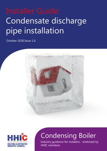
Installer Guide:Condensate dischargepipe installationOctober 2018 Issue 1.0Condensing BoilerIndustry guidance for installers - endorsed byHHIC members
In April 2005 revisions to the Building Regulations came into force, stating that all replacement gas or oil boilers must be a condensing type. Theintroduction of condensing boilers has been fundamental in reducing theUK’s carbon emissions.In 2010 and again in 2018 the UK experienced prolonged spells of sub-zerotemperatures down to minus 20 centigrade and below in many areas. Thisresulted in a significant increase in the number of calls to boilermanufacturers and heating engineers from householders with condensing (highefficiency) boilers where the condensate discharge pipe had frozen and becomeblocked with ice causing the boiler to shut down. In the vast majority of casessuch problems occur where the condensate discharge pipe is locatedexternally to the building for some part or all of its length.British Standards, Building Regulations and industry guidance currently advise onhow condensate discharge pipes should, be run either internally or externally, ora combination of both. This document gives guidance on how to install the pipesin order to reduce the possibility of freezing.However, in certain circumstances this guidance may not be sufficient toprevent freezing in extreme conditions with widespread and prolongedsub-zero temperatures.With the UK weather patterns showing more “extremes” in future due to theeffects of global climate change, the following guidance updates previousrecommendations on condensate discharge pipe installation. In addition to thisguidance all other technical requirements for condensate discharge installationgiven in British Standard BS 6798:2014, or in boiler manufacturers’ installationinstructions should still be followed.****Boiler Manufacturer’s Warranty InformationIt should be noted that where the manufacturer’s instructions havenot been followed then the boiler warranty may not be valid.Note - the Benchmark Commissioning checklistsupplied with the boiler and detailed in the manufacturer’sinstructions requires the heating engineer to confirm thatthe condensate drain has been fitted correctly.
Summary of main requirementsInternal Condensate Pipe Discharge ConnectionWhere an installer is fitting a new or replacement boiler, the condensatedischarge pipe should be connected to an internal “gravity discharge point”such as an internal soil stack (preferred method), internal kitchen orbathroom waste pipe such as sink, basin, bath or shower waste. External pipesfrom sink wastes or washing machine outlets should be a minimum of 30mminternal diameter, insulated with waterproof UV resistant material, terminatedbelow the grid but above the water line and a suitable drain/leaf guard fitted.The end of the waste pipe should be cut at 45 degrees where it terminatesinto the grid to help reduce the potential for the pipe to freeze.Condensate PumpsWhere it is not possible to connect the boiler condensate discharge pipe to aninternal “gravity discharge point” then the installer should use a condensatepump connected to a suitable internal connection point such as an internalsoil stack (preferred method), internal kitchen or bathroom waste pipe such asa sink, basin, bath or shower waste.Existing InstallationsWhen servicing or repairing a boiler the heating engineer should check anyboiler installations especially those that have external condensate drains tosee if they can be terminated internally or upgraded to the latest guidance.The responsible person (home owner) should be advised and it isrecommended that the installer completes the responsible persons frozencondensate information leaflet as a suitable means for advising the work thatis required. See annex AThis guidance should be followed where work is carried out to “upgrade” thecondensate discharge system to reduce the risk of freezing in extremeconditions and it is recommended that the condensate pipe is identified with asuitable label or marking even if the responsible person does not go ahead withthe upgrade so as to allow easier identification in the future.
Manufacturers InstructionsManufacturer’s instructions must be followed for the correct connection of thecondensate discharge pipe from the boiler as this may vary due to the designof the boiler. For example a visible air break and trap is not required if there is atrap with a minimum condensate seal of 75 mm incorporated into the boiler.Internal Pipe Run In Unheated SpacesCondensate discharge pipes that are routed in an unheated space such as a loftor garage should be insulated to prevent freezing.Internal Condensate Pipe Discharge TerminationInternal condensate discharge pipework must be a minimum of 19mm ID(typically 22mm OD) plastic pipe or as per manufacturer’s instructions and thisshould “fall” a minimum of 45mm per metre away from the boiler, taking theshortest practicable route to the termination point.(45mm as per BS6798, 52mm per metre as per industry practice is specified in the followingdiagrams)To minimise the risk of freezing during prolonged sub-zero conditions, aninternal “gravity discharge point” such as an internal soil stack (preferredmethod), internal kitchen, utility room or bathroom waste pipe e.g. from a sink,basin, bath or shower should be adopted, where possible.Note - A suitable permanent connection to the foul waste pipe should be used.Figures 1, 2(a), 2(b) show appropriate connection methods.Manufacturers Instructions must be referred to wheninstalling boiler condensate discharge pipes
Figure 1 – Connection of condensate discharge pipe to internal soil and vent stack.Note – Check manufacturer’s instructions to see if an air break is required.18257346Key1 Boiler2 Visible air break3 75 mm trap4 Visible air break and trap not required if there is a trap with a minimum condensate sealof 75 mm incorporated into the boiler5 Soil and vent stack6 Invert7 450 mm minimum up to three storeys8 Minimum internal diameter 19 mmManufacturers Instructions must be referred to wheninstalling boiler condensate discharge pipes
Internal Condensate Pipe Discharge TerminationFigure 2(a) – Connection of a condensate discharge pipe downstream of a sink, basin, bath orshower waste trap.Note – Check manufacturer’s instructions to see if an air break is required.182711125439106Key1 Boiler2 Visible air break3 75 mm trap4 Visible air break and trap not required if there is a trap with a minimum condensate sealof 75 mm incorporated into the boiler. In this case the 100 mm is measured to the trapin the boiler.5 Sink, basin, bath or shower6 Open end of condensate discharge pipe direct into gully 25 mm min below grating butabove water level; end cut at 45 Note – the maximum external condensate discharge length is 3 metres7 Sink lip8 Minimum internal diameter 19 mm9 Pipe size transition10 Minimum internal diameter 30 mm11 Water/weather proof insulation12 Drain cover/leaf guardManufacturers Instructions must be referred to wheninstalling boiler condensate discharge pipes
Internal Condensate Pipe Discharge TerminationFigure 2(b) – Connection of a condensate discharge pipe upstream of a sink, basin, bath orshower waste trap16248910375Key1 Boiler2 Visible air break at plug hole – alternative connection can be below sink trap3 75 mm sink, basin, bath or shower waste trap4 Sink, basin, bath or shower with integral overflow5 Open end of condensate discharge pipe direct into gully 25 mm min below grating butabove water level; end cut at 45 Note – the maximum external condensate discharge length is 3 metres6 Minimum internal diameter 19 mm7 Pipe size transition8 Minimum internal diameter 30 mm9 Water/weather proof insulation10 Fit drain cover/leaf guardManufacturers Instructions must be referred to wheninstalling boiler condensate discharge pipes
Internal Condensate Pipe Discharge TerminationThe possibility of waste pipes freezing downstream of the connection pointshould be considered when determining a suitable connection point - e.g. aslightly longer pipe run to an internal soil stack may be preferable to a shorterrun connecting into a kitchen waste pipe discharging directly through the wall toan external drain.Note - Where “gravity discharge” to an internal termination is not physicallypossible (e.g. the discharge point is above the appliance location, or access isobstructed by a doorway), or where very long internal pipe runs would berequired to reach a suitable discharge point, then a condensate pump should beused.External waste pipes from kitchens, utility rooms or bathrooms such as sink,basin, and bath or shower waste outlets should be insulated with waterproof UVresistant, class 0 material, terminated below the grid but above the water lineand a drain/leaf guard fitted. The waste pipe should be cut at 45 degrees whereit terminates into the grid. (See insulation section for guidance on suitablematerials).Condensate PumpsUse of a Condensate Pump to an Internal TerminationCondensate can be removed using a proprietary condensate pump, of aspecification recommended by the boiler or pump manufacturer. In order tominimise the risk of freezing during prolonged sub-zero spells, one of thefollowing methods internal to the property for terminating the boiler condensatepump to a foul water discharge point should be adopted such as an internal soilstack (preferred method), internal kitchen, utility room or bathroom waste pipesuch as sink, basin, and bath or shower waste. Figure 3 shows a typicalconnection method.Manufacturers Instructions must be referred to whenManufacturersbe referredto wheninstallingboiler Instructionscondensate mustdischargepipesinstalling boiler condensate discharge pipes
Internal Condensate Pipe Discharge TerminationFigure 3 – Connection of a condensate pump - typical method (NB manufacturer’s detailedinstructions should be followed).Note – Any external pipe work should be insulated, pipe cut at 45 degrees and a drain/ leafguard fitted.3Key1 Condensate discharge from boiler2 Condensate pump3 Visible air break at plug hole4 Sink or basin with integrated overflow5 75mm sink waste trap415262834971051Key1 Boiler2 Visible air break at plug hole3 75 mm sink, basin, bath or showerwaste trap4 Sink, basin, bath or shower withintegral overflow5 Open end of condensate dischargepipe direct into gully 25 mm min belowgrating but above water level; end cutat 45 Note – the maximum externalcondensate discharge length is 3 metres6 Minimum internal diameter 19 mm7 Pipe size transition8 Minimum internal diameter 30 mm9 Water/weather proof insulation10 Fit drain cover/leaf guardManufacturers Instructions must be referred to whenManufacturersbe referredto wheninstalling alling boiler condensate discharge pipes
External ConnectionsExternal ConnectionsOnly fit an external boiler condensate drain connection if an internal gravity orpumped connection is impractical to install.The pipe work from the boiler should be of a minimum 19mm ID or as permanufacturer’s instructions and the condensate discharge pipe shall be run in astandard drainpipe material, e.g. poly (vinyl chloride) (PVC), un-plasticized poly(vinyl chloride) (PVC-U), acrylonitrile butadiene-styrene (ABS), polypropylene (PP)or chlorinated poly (vinyl chloride) (PVC-C).Note - Fixing centres for brackets should be a maximum of 300mm for flexible pipe and500mm for solid pipe and manufacturer’s recommendations should be followed.The condensate pipe should be run internally as far as possible before goingexternally and the pipe diameter should be increased to a minimum of 30mmID (typically 32mm OD) before it passes through the wall. The angle of the pipeshould slope downwards by at least 3 degrees as it passes through the wall toassist in maintaining a good velocity as the condensate exits the building.The external pipe run should be kept as short as possible to a maximum of 3metres, taking the most direct and “most vertical” route to the discharge point,with no horizontal sections in which condensate might collect.ManufacturersInstructionsmustreferredto whenManufacturersInstructionsmustbe bereferredto tructionsmustbe referredto wheninstalling boiler condensate discharge pipes
External ConnectionsFigure 4 – Connection of condensate discharge pipe to external soil and vent stack1112895710346Key1 Boiler2 Visible air break3 75 mm trap4 Visible air break and trap not required if there is a trap with a minimum condensate sealof 75mm incorporated into the boiler.5 Soil and vent stack6 Invert7 450mm minimum upto three storeys8 Minimum internal diameter 19 mm9 Pipe size transition point10 Minimum internal diameter 30mm11 Water/weather proof insulationManufacturers Instructions must be referred to whenManufacturersbe referredto wheninstalling alling boiler condensate discharge pipes
External ConnectionsAlternative SolutionsCold weather protection methods approved or endorsed by boiler manufacturersand/or service organisations may be adopted if these are considered suitable bythe parties involved. It is the responsibility of the manufacturer of these productsto ensure they have completed the necessary testing or calculations to ensurethe product offers suitable protection to prevent the condensate pipe fromfreezing. The product manufacturer should provide information as to what levelof external temperature and for what time period the product can protect againstsub-zero temperatures, i.e. -15 C for 48 hours. BS6798 refers to devices thatpump the condensate produced by a condensing boiler to a fine misting nozzlein the boiler flue terminal so that the condensate is discharged with the hot fluegas. (BS6798 section 6.3.8 note 4). The boiler manufacturer’s instructions willprovide advice regarding fitting and siting of the flue terminal to ensure safedisposal of the condensate.Additional MeasuresAt least one of the following measures should be fitted in addition to themeasures detailed above for external condensate discharge pipes Insulate external pipe with a minimum thickness of insulation to be 19mm“O” class PVC coated material. Fit trace heating – with insulation as recommended by manufacturer. Fit internal auxiliary(additional) high volume syphon unitAuxiliary Syphon – Fitted InternallyAuxiliary siphons fitted inside the premises assist with the siting of the boilerwhere an external condensate pipe must be fitted. The storage capacity of theauxiliary siphon increases the volume of condensate discharge reducing the riskof freezing. A further reduction in the potential for the pipe to freeze is achievedwhen combined with the external insulation to whenManufacturersInstructionsmustbe bereferredto whenManufacturersInstructionsmustbe referredto lingboilercondensatedischargepipesinstalling boiler condensate discharge pipes
External ConnectionsElectric Trace HeatingTrace heating with an external thermostat can be fitted to the externalcondensate pipe to raise the temperature of the condensate pipe in freezingconditions. Trace heating takes the form of an electrical heating element run inphysical contact along the length of the condensate pipe. The pipe is usuallycovered with thermal insulation to retain heat losses from the pipe. Heatgenerated by the element then maintains the temperature of the pipe. If such asystem is used then the installation instructions of the trace heatingmanufacturer and any specific recommendations regarding pipe diameter,insulation, etc. should be followed. All other relevant guidance on condensatedischarge pipe installation should also be followed.Insulation MaterialsInsulation used for external condensate pipes, sink or washing machine wastepipes should be of class ‘O’ grade with an outer coating that is weather proof,bird/animal proof, and UV resistant finish. A minimum of 19mm thick insulationis recommended for 32mm external pipes.Use of Air Breaks In Condensate Discharge PipesHeating engineers should follow manufacturer’s instructions on the use of airbreaks in condensate discharge pipes. A visible air break is not required if theboiler condensate trap has a minimum condensate seal of 75mm incorporatedinto the boiler.Connecting to a rain water downpipe/External Soil StackWhen an external soil stack or rain water downpipe is used as the termination(NB only permissible if this downpipe passes to a combined foul and rainwaterdrainage system) an external air break must be installed between the condensatedischarge pipe and the downpipe to avoid reverse flow of rainwater/sewage intothe boiler should the downpipe itself become flooded or frozen.Figure 5 shows a suitable connection method. Pipe insulation should be fitted.Manufacturers InstructionsInstructions mustmust bebe referredreferred toto whenwhenManufacturersinstalling boilerboiler condensatecondensate dischargedischarge pipespipesinstalling
External ConnectionsFigure 5 – External termination to rainwater downpipe (NB only combined foul/rainwaterdrain)5139267104811Key1 Condensate discharge pipe from boiler2 Pipe size transition point3 Water/weather proof insulation4 43mm 90 male/female bend5 External rain water pipe into foul water6 External air break7 Air gap8 68mm PVCu strap on fitting9 Minimum internal diameter 19mm10 Minimum internal diameter 30mm11 End cut at 45 ManufacturersInstructionsmustreferredto whenManufacturersInstructionsmustbe bereferredto cturersInstructionsmustbe referredto ling boiler condensate discharge pipes
External ConnectionsExternal Termination of the Condensate PipeWhere the condensate discharge pipe is terminated over an open foul drain orgully, the pipe should terminate below the grating level, but above water level,in order to minimise “wind chill” at the open end. Pipe drainage and resistanceto freezing will be improved if the termination end of the condensate pipe is cutat 45 degrees as opposed to a straight cut.The use of a drain cover (such as those used to prevent blockage by leaves)must be fitted to offer further protection from wind chill. Figure 6 (followingpage)shows a suitable connection method. Where the condensate drain pipeterminates in a purpose-designed soakaway (see BS 6798:2014 or boilerinstallation manual for soakaway design requirements) any above-groundsection of condensate discharge pipe should be run and insulated as describedabove. Figure 7 (following page) shows a suitable connection method.Unheated Areas in BuildingsInternal condensate drainage pipes run in unheated areas such as lofts,basements and garages should be treated as external connections and insulatedaccordingly. Weather proof materials may not be necessary and should beassessed by the heating engineer.Use of Air Breaks In Condensate Discharge PipesInstallers should follow the manufacturer’s instructions on the use of air breaksin condensate discharge pipes. A visible air break and trap is not required if theboiler condensate trap has a minimum condensate seal of 75 mm incorporatedinto the boiler.Manufacturers Instructions must be referred to whenManufacturers Instructions must be referred to wheninstalling boiler condensate discharge pipesinstalling boiler condensate discharge pipes
External ConnectionsFigure 6 – External drain, gully or rainwater hopper1291057113486Key1 Boiler2 Visible air break3 38mm minimum trap4 Visible air break and trap not required if there is a trap with a minimum condensate sealof 38 mm incorporated into the boiler – refer to manufacturers instructions5 External length of pipe 3 m maximum6 Open end of condensate discharge pipe direct into gully 25 mm min below grating butabove water level; end cut at 45 7 Minimum internal diameter 19 mm8 Pipe size transition point9 Minimum internal diameter 30 mm10 Water/weather proof insulation11 Fit drain cover/leaf guardManufacturers Instructions must be referred to wheninstalling boiler condensate discharge pipes
External ConnectionsFigure 7 – Example of a purpose made soakaway8111910234567Key1 Condensate discharge pipe from boiler2 Ground (this section of the condensate discharge pipe may be run either above or belowround level); End cut at 45 3 Diameter 100 mm minimum plastic tube4 Bottom of tube sealed5 Limestone chippings6 Two rows of three 12 mm holes at 25 mm centres, 50 mm from bottom of tube and facingaway from house7 Hole depth 400 mm minimum by 300Manufacturersmm diameter Instructions must be referred to w8 Minimum internal diameter 19 mm installing boiler condensate discharge pipes9 Pipe size transition point10 Minimum internal diameter 30 mm11 Water/weather proof insulationManufacturers Instructions must be referred to hargepipesManufacturersbe referredto wheninstalling boiler condensate discharge pipes
Our customer information guide on frozen boiler condensatedischarge is also available for download.It includes a condensate assessment form, for engineers tocomplete and advice to customers during extreme cold weatherconditions.Customer information:Frozen boilercondensate dischargeOctober 2018 Issue 1.0Condensing BoilerGuidance and advice for customers- endorsed by the Heating andHotwater Industry Council, HHICinfo@hhic.org.uk01926 513777@HHICCamden HouseWarwick RoadKenilworthCV8 1TH
Manufacturers Instructions must be referred to when installing boiler condensate discharge pipes Figure 2(a) - Connection of a condensate discharge pipe downstream of a sink, basin, bath or shower waste trap. Note - Check manufacturer's instructions to see if an air break is required. Key 1 Boiler 2 Visible air break 3 75 mm trap