Transcription
QUALITY CRIMPING HANDBOOKQUALITY CRIMPINGHANDBOOKBringing People & Technology Together, WorldwideSMCorporate Headquarters : 2222 Wellington Court, Lisle, IL, 60532, U.S.A., Tel : 630-969-4550Application Tooling Division : 1150 E. Diehl Rd., Naperville, IL 60563, Tel : 630-969-4550European Headquarters : Munich, Germany, Tel : 49-89-413092-0Far East North Headquarters : Kanagawa, Japan, Tel : 81-462-2336Far East South Headquarters : Jurong Town, Singapore, Tel : 65-268-6868Printed in U.S.A.Order Number - 63800-00295M JI 6/96 1996, Molex IncorporatedIllustrations by Julie Theis-PanePRODUCED BY THE MOLEXAPPLICATION TOOLING GROUP
10.0 NOTESTable of ContentsIntroduction To Crimp Technology . 51.0Purpose. 62.0Scope. 73.0Definitions. 94.0Associated Materials . 155.0Procedure5.1Tool Setup. 166.0Measurement . 206.1Pull Force. 206.2Crimp Height . 237.0Process Control7.17.27.37.48.0. 24Process CapabilityProductionVisual InspectionControl ChartingTrouble Shooting8.18.28.38.48.58.638. 16. 24.26.26.26. 29Wire Preparation. 29Bellmouth and Cut-Off Tab Length 29Conductor Brush and Insulation Position 31Insulation Crimp. 33Crimp Height . 35Pull Force. 359.0Wire Gauge Chart10.0Notes. 36. 383
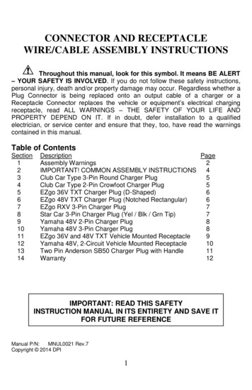
INTRODUCTION TOCRIMP TECHNOLOGY9.0 Wire Gauge ChartAWGWIRE AREASTRANDINGWIRE DIAMETER CIRCULARWIRE BREAKsq. inchsq. .2336Developed to replace the need to solder terminations, crimping technologyprovides a high quality connection between a terminal and a wire at a relatively low applied cost. The methods for applying crimp terminations depend onthe application and volume, and range from hand-held devices to fully-automated systems. The application methods include a basic hand tool, a press anddie set, a stripper crimper or a fully automatic wire processing system. But nomatter what method is used, the setup of each tool is critical for achieving aquality crimp.Today, many OEM companies are using Statistical Process Control (SPC) tocontinuously improve their crimp terminations. Crimp termination is a complex process and to ensure consistent quality it is necessary to understand thevariability and inter-relational interactions that the technology involves.Without a thorough understanding of the crimping process and all the factorsthat can affect it, the end result may not meet expectations. The three key elements in the crimping process are the terminal, the wire and the tooling.TerminalFor most applications, it is not economically practical for connector manufacturers to design a terminal to accept one wire size, one wire stranding, and oneinsulation diameter (UL type). Most terminals accommodate many wire sizes,stranding, and a range of insulation diameters so the terminals are designed tomeet acceptable levels over this entire range.WireThe wire stranding and insulation type can vary widely within one wire size.For example, there is more than 18% more material in an 18 AWG x 19 strandwire than an 18 AWG x 16 strand. The insulation diameter of an 18 AWG wirecan range from .070" (1,78 mm) to over .180" (4,57 mm). Wire strands canbe copper, tinned, overcoated, or topcoated. Wire insulation materials, thickness, and durometers vary from application to application.ToolingWhat type of tooling does the application require? Does the applicationrequire hand stripping of the wire or does the volume dictate an automaticwire stripping machine? Does the application and volume require hand tools,press and die, or fully automatic wire process machines? Crimping with amanual hand tool, semi-automatic press and die, or fully automatic wireprocessor, all involve different levels of variability. The terminal, wire, andtype of application tooling all affect the quality of the completed terminations.5
1.0 PURPOSE8.0 TROUBLE SHOOTING8.5 CRIMP HEIGHTProblemThe tooling setup is critical in determining the quality of the finished crimp.The attributes that need to be considered include crimp height, conductorbrush, bellmouth, cut-off tab, strip length and insulation position. Variabilityin one or more of these attributes can reduce the measured pull force. It canbe difficult to establish acceptable variability limits because the attributes allinteract with one another. For example, a track adjustment for bellmouth alsowill change the cut-off tab length and the insulation wire position while striplength and wire locations affect the conductor brush and insulation position.Adjusting the insulation crimp height may result in a slight change to theconductor crimp height measurement. It may be necessary for the setup person to make multiple adjustments before establishing an optimal setup. Theorder the setup is done may help reduce the number of repetitions requiredfor an optimum setup. Chapter 5 has a flowchart for a process setup whileChapter 7 is a trouble shooting guide for common problems. Using StatisticalProcess Control (SPC) during the crimping process can help minimize theParts per Million (PPM) reject levels. Chapter 6 provides a general explanation of the benefits of using SPC.This handbook is structured so that parts, or all, of its contents can be used asa procedural guide for ISO requirements.CauseChanged crimp toolingCrimp height off target(Fig. 42)Changed crimp press(shut height)Changed press type(manufacturer)Changed terminal reel(lot code)Adjust tooling back to targetChanged tooling set-upDamaged or worn toolingWire variabilityTerminal variabilityCrimp height variability to high(Fig. 43)Inspect incoming product.Damaged, loose, or worntoolingTooling replacement ortighteningMeasurement errorGage capability analysisTerminal spring back too great,over crimpingCut or missing wire strandsCrimp height adjustmentStripping process adjustmentCauseSolutionCut or nicked strandsCheck the stripping processCrimp height too lowAdjust crimp height8.6 PULL FORCEProblemWire breaks before conductorcrimp - low pull force (Fig. 45)Wire pulls out of conductor grip- low pull force (Fig. 45)Small or no bellmouthAdjust tooling trackInsulation crimp throughinsulation wallRaise insulation crimp heightCrimp height too highAdjust crimp heightSmall or no conductor brushIncrease strip lengthConductor bellmouth too bigAdjust tooling trackGold terminal applicationTerminal material thickness toosmallLight serrations on terminal6SolutionChanged wire type, vendor, orstrandingChanged insulation color ordurometerThis handbook provides general guidelines and procedures for understandingand achieving acceptable crimp terminations. A Glossary in Chapter 3 listscommon terms and definitions. Chapter 4 lists the tools that are necessary totake accurate measurements and evaluate the crimp's acceptability.35Evaluate the terminalapplicationContact your local salesengineer
2.0 SCOPEThis handbook is intended for Molex customers who are crimping Molexopen barrel crimp terminals and are using Molex tooling, primarily in semiautomatic or automatic wire processing termination methods. The handbook'scontents may slightly differ from other connector manufacturers' guidelinesor individual company procedures.Figure 41 - Optimal Crimp Height ChartFigure 42 - Crimp Height Off TargetThis handbook provides a basic overview of what to look for in an acceptablecrimp. It is not intended to replace individual product and/or tooling specifications. Individual terminals or applications may have special requirements.Tooling limitations also may not permit an attribute to be adjusted to meetoptimum requirements.Figure 43 - Crimp Height Variability Too HighFigure 44 - Optimal Pull Force ChartFigure 45 - Low Pull Force Chart7
8.0 TROUBLE SHOOTING8.4 INSULATION CRIMPProblemCauseTerminal surrounds less than88% of a large diameter wire(Fig. 37)Crimp too loose, not enoughterminal insulation barrelTerminal contacts less thanToo much terminal insulation50% of a small diameter wirebarrel(Fig. 38)SolutionTighten insulation crimp heightEvaluate terminalEvaluate terminalInsulation crimp barrels cutthrough insulation intoconductor strands (Fig. 39)Crimp too tightAdjust insulation crimpheight*Insulation not firmly grippinginsulation, fails bend test(Fig. 40)Crimp too looseAdjust insulation crimp heighttighter*Inexpensive hand tools provide no adjustment for the insulation crimp. Ahand tool is intended for low volume applications. Although you are not ableto adjust the insulation crimp on a hand tool, an insulation crimp whichpierces the insulation may still be considered acceptable for many applications. This criteria only applies to hand tools due to their low speed crimpcycle. If the insulation crimp pierces the insulation, the wire strands tend tomove aside without damage.Figure 1 - Terminal Anatomy833
3.0 DEFINITIONS(Anatomy of a Crimp Termination)Figure 34 - Preferred Insulation CrimpBEND TESTOne way to test the insulation crimp is by bending the wire several times andthen evaluating the movement of the insulation and wire strands. As a generalrule, the insulation crimp should withstand the wire being bent 60 to 90degrees in any direction, several times. Use care when working with smallwire sizes so the wire at the back of the insulation crimp does not shear.Figure 33 - Preferred Insulation CrimpFigure 36 - Acceptable Insulation CrimpCONDUCTOR BRUSHThe conductor brush is made up of the wire strands that extend past the conductor crimp on the contact side of the terminal. This helps ensure thatmechanical compression occurs over the full length of the conductor crimp.The conductor brush should not extend into the contact area.CONDUCTOR CRIMPThis is the metallurgical compression of a terminal around the wire's conductor. This connection creates a common electrical path with low resistance andhigh current carrying capabilities.Figure 35 - Acceptable Insulation CrimpFigure 38 - Marginal Insulation CrimpFigure 37 - Marginal Insulation CrimpFigure 40 - Marginal Insulation CrimpFigure 39 - Marginal Insulation CrimpBELLMOUTH (FLARE)The flare that is formed on the edge of the conductor crimp acts as a funnelfor the wire strands. This funnel reduces the possibility that a sharp edge onthe conductor crimp will cut or nick the wire strands. As a general guideline,the conductor bellmouth needs to be approximately 1 to 2x the thickness ofthe terminal material *.* Consult individual terminal specifications32CONDUCTOR CRIMP HEIGHTThe conductor crimp height is measured from the top surface of the formedcrimp to the bottom most radial surface. Do not include the extrusion points inthis measurement (See Figure 2, pg. 10). Measuring crimp height is a quick,non-destructive way to help ensure the correct metallurgical compression of aterminal around the wire's conductor and is an excellent attribute for processcontrol. The crimp height specification is typically set as a balance betweenelectrical and mechanical performance over the complete range of wire stranding and coatings, and terminal materials and platings. Although it is possibleto optimize a crimp height to individual wire strandings and terminal platings,one crimp height specification is normally created.CUT-OFF TAB LENGTHThis is the material that protrudes outside the insulation crimp after the terminal is separated from the carrier strip. As a general rule, the cut-off tab isapproximately 1.0 to 1.5x terminal material thickness *. A cut-off tab that istoo long may expose a terminal outside the housing or it may fail electricalspacing requirements. In most situations, a tool is setup to provide a cut-offtab that is flush to one material thickness.* Consult individual terminal specifications requirements.9
8.0 TROUBLE SHOOTING8.3 CONDUCTOR BRUSH AND INSULATION POSITIONProblemCauseSolutionInsulation under cond. crimp,good conductor brush (Fig. 26)Strip length too shortCheck specification, adjust striplength longerBench - Wire stop positionincorrectWire Processing - Pressposition incorrectAdjust wire stop to center oftransition areaAdjust press position awayfrom wireInsulation under conductorcrimp, long conductor brushlength (Fig. 27)Insulation under conductorcrimp, short or no conductorbrush (Fig. 28)Strip length too shortCheck specification, adjust striplength longerRe-adjust wire stop position forbench applications ORRe-adjust press position forwire processing applicationsCheck specification, adjust striplength shorterRe-adjust wire stop position forStrip length too longInsulation edge centered in tranbench applications ORsition area, conductor brush tooRe-adjust press position forlong (Fig. 29)wire processing applicationsIrregular wire cut-off or strandsCheck for worn strippingpulled from insulation bundletoolingInsulation edge centered in transition area, conductor brush tooshort (Fig. 30)Insulation edge under insulationcrimp, good or long conductorbrush (Fig. 31)Strip length too shortCheck specification, adjust striplength longerRe-adjust wire stop position forbench applications ORRe-adjust press position forwire processing applicationsStrip length too longCheck specification, adjust striplength shorterRe-adjust wire stop position forbench applications ORRe-adjust press position forwire processing applicationsTerminal Cross SectionFigure 2 - Terminal AnatomyInsulation edge under insulationcrimp, short or no conductorbrush (Fig. 32)10Bench - Wire stop positionincorrectWire Processing - Pressposition incorrectAdjust wire stop to center oftransition areaAdjust press position awayfrom wireVerify operators wireplacement abilityOperator training, reducecrimping rate31
Figure 26 - Insulation Under Conductor Crimp,Good Conductor BrushEXTRUSIONS (FLASH)These are the small flares that form on the bottom of the conductor crimpresulting from the clearance between the punch and anvil tooling. If the anvilis worn or the terminal is over-crimped, excessive extrusion results. Anuneven extrusion may also result if the punch and anvil alignment is not correct, if the feed adjustment is off, or if there is insufficient/excessive terminaldrag.INSULATION CRIMP (STRAIN RELIEF)This is the part of the terminal that provides both wire support for insertioninto the housing and allows the terminal to withstand shock and vibration.The terminal needs to hold the wire as firmly as possible without cuttingthrough to the conductor strands. The acceptability of an insulation crimp issubjective and depends on the application. A bend test is recommended todetermine whether or not the strain relief is acceptable for each particularapplication.Figure 25 - Optimal CrimpFigure 28 - Insulation Under Conductor Crimp,Short or No Conductor BrushFigure 27 - Insulation Under Conductor Crimp,Conductor Brush Too LongFigure 30 - Conductor Brush Too ShortINSULATION CRIMP HEIGHTMolex does not specify insulation crimp heights because of the wide varietyof insulation thickness, material, and hardness. Most terminals are designedto accommodate multiple wire ranges. Within the terminals range, an insulation diameter may not completely surround the wire or fully surround thediameter of the wire. This condition will still provide an acceptable insulationcrimp for most applications. A large insulation should firmly grip at least 88% of the wire.A smaller insulation should firmly grip at least 50% of the wireand firmly hold the top of the wire.To evaluate the insulation section cut the wire flush with the back of the terminal. Once the optimum setting for the application is determined it is important to document the insulation crimp height. Then, as part of the setup procedure the operator can check the crimp height.Figure 29 - Conductor Brush Too LongFigure 32 - Insulation Under Insulation Crimp,Conductor Brush Too ShortFigure 31 - Insulation Under Insulation Crimp,Conductor Brush Too Long30INSULATION POSITIONThis is the location of the insulation in relation to the transition area betweenthe conductor and insulation crimps. Equal amounts of the conductor strandsand insulation needs to be visible in the transition area. The insulation position ensures that the insulation is crimped along the full length of the insulation crimp, and that no insulation gets crimped under the conductor crimp.The insulation position is set by the wire stop and strip length for benchapplications. For automatic wire processing applications the insulation position is set by the in/out press adjustment.11
8.0 TROUBLE SHOOTING8.1 WIRE PREPARATIONProblemIrregular Insulation Cut (Fig. 16)Figure 3 - Strip LengthCut or nicked strands (Fig. 17)Irregular conductor cut pulled strands (Fig. 18)Figure 4 - ProcessWire length variability too high(Fig. 19)Wrong strip length (Fig. 19)CauseSolutionWorn toolingReplace toolingCut depth too shallowAdjust cut depthDamaged toolingReplace toolingCut depth too deepAdjust cut depthConductor not on wire centerContact wire supplierWorn toolingReplace toolingWire cut depth too shallowAdjust cut depthWire drive rollers/belts wornReplace belts/rollersInsulation durometer too hardIncrease drive pressureWire straightener too loose ortightAdjust wire straightenerIncorrect setupRe-setup toolingFigure 5 - Pull Force Tester8.2 BELLMOUTH AND CUT-OFF TAB LENGTHProblemFigure 7 - In Press Terminal PositionFigure 6 - Press Shut Height12CauseSolutionLow pull force (Fig. 21 & 22)Excessive bellmouth no cut-off Adjust track position for smalltabcut-off tabExcessive bellmouth, cut-off tab Check for worn or incorrectpunch tooling and replacealrightCut or nicked strands (Fig. 23)No bellmouth and/or excessivecut-off tabLong cut-off tab (Fig. 24)Good bellmouth and excessivecut-off tab29Adjust track positionCheck for camber in terminalstripCheck for worn cut-off andreplace if necessaryCheck for worn punch tooling,replace, and re-adjust track
STRIP LENGTHThe strip length is determined by measuring the exposed conductor strandsafter the insulation is removed. The strip length determines the conductorbrush length when the insulation position is centered.Figure 17 - Cut StrandsFigure 16 - Irregular Insulation CutFigure 18 - Pulled StrandsFigure 19 - Wire Length Variabilityor Wrong Strip LengthPROCESSThe combination of people, equipment, tooling, materials, methods and procedures needed to produce a crimp termination. Process Control is used totrack attributes over time to aid in the detection of change to the process.Detecting a process change when it happens helps prevent many thousands ofbad crimps.PULL FORCE TESTINGPull Force Testing is a quick, destructive way to evaluate the mechanicalproperties of a crimp termination. When making a crimp, enough pressuremust be applied to breakdown the oxides that may build up on the strippedconductor and the tin plating on the inside of the terminal grip. This is necessary to provide a good metal-to-metal contact. If this does not occur, resistance can increase. Over crimping a crimp termination will reduce the circular area of the conductor and increase resistance.Pull Force testing is also a good indicator of problems in the process. Cut ornicked strands in the stripping operation, lack of bellmouth or conductorbrush, or incorrect crimp height or tooling will reduce pull force. Wire properties and stranding, and terminal design (material thickness and serrationdesign), also can increase or decrease pull force levels.Figure 20 - Optimal CrimpFigure 21 - Excessive BellmouthFigure 22 - Excessive Bellmouth, No Cut-off TabSHUT HEIGHTThe distance, at bottom dead center on a press, from the tooling mountingbase plate to the tooling connection point on the ram of the press.TERMINAL POSITIONThe terminal position is set by the alignment of the terminal to the formingpunch and anvils, and the carrier strip cut-off tooling. The tool set-up determines conductor bellmouth, cut-off tab length, and terminal extrusions.Figure 23 - No Bellmouth, Excessive Cut-off TabFigure 24 - Excessive Cut-off Tab, Good Bellmouth2813
It indicates that a process shift occurred between measurement 12 and 13. Thistype of shift could occur due to a change in wire, a change in terminal lots, ajam in the machine that damaged the tooling, a change in operators, or anadjustment to the insulation crimp. Since the measurements are still withinspecification, would you stop production to adjust crimp height?A shift in the process due to a change in material may warrant a crimp heightadjustment. A shift after a jam would not indicate an adjustment, but a closeevaluation of the tooling. A shift in the process between operators would notindicate an adjustment, but an evaluation of measurement capability. The purpose of a control chart is to identify what caused the shift in process to justify ifan adjustment to the process is needed.Figure 8 - CaliperFigure 9 - Eye LoopFigure 11 - Pocket RulerFigure 10 - Crimp MicrometerFigure 12 - Toolmaker’s Microscope1427
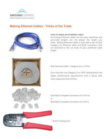
4.0 ASSOCIATED MATERIALS7.2 PRODUCTIONBefore the tool is ready for production, the level of capability needs to beestablished. Many harness manufacturers run only a few hundred or few thousand wires at one time. In this case, it is not practical or economical to run atwenty-five piece capability with every set-up.7.3 VISUAL INSPECTIONIt needs to be standard operating procedure for the operator to manually faneach bundle of crimped wires and visually check bellmouth, conductor brush,insulation position, cut-off tab length, and insulation crimp.7.4 CONTROL CHARTINGCrimp height is typically control charted because it is a quick nondestructivemeasurement and is critical for the termination's electrical and mechanicalreliability. There are three primary purposes for control charting. One, the number of setup samples is usually small, with limited statistical value. Two, sincespecial cause effects on a process are irregular and unpredictable, it is necessary to be able to catch changes in the process as soon as they occur. This prevents thousands of terminations from being scrapped after the run is over.Three, and most important, this data is necessary to assess and improve thecrimp process.Once the tooling process is setup and the wire size does not change, keep onecontrol chart for wire color changes, wire length changes, terminal materialchanges, or setup adjustments. Record the data point on the chart before making a crimp height adjustment. If data is recorded after each adjustment, theprocess is likely to assume control and provide little data for improving theprocess. The operator needs to make as many notes as possible on the chart.The only truly effective and economically sensible way to manage a manufacturing process is to understand, monitor and reduce sources of variability thatare inherent to the process itself. Every minute required for setup or adjustments is unproductive. What does this sample chart tell us?CALIPERA gage, consisting of two opposing blades, for measuring linear dimensionalattributes.EYE LOOPA magnification tool, normally 10x power or greater, which is used to aidvisual evaluation of a crimp termination.CRIMP MICROMETERThis is a micrometer specifically designed to measure crimp height. Themeasurement is taken in the center of the crimp so it is not influenced by theconductor bellmouth. It has a thin blade that supports the top of the crimpwhile a pointed section determines the bottom most radial surface.RULER (POCKET SCALE)This is used to estimate the five piece measurement of bellmouth, cut-off tab,conductor brush, wire position, and strip length. The recommended maximumresolution is .5 mm (.020 in).PULL TESTER (Reference fig. 5, pg.12)A device used to determine the mechanical strength of a crimp termination.Most pull testing is done with a device that clamps the wire, pulls at a setspeed, and measures force by means of a load cell. A pull tester also can beas simple as hanging fixed weights on the wire for a minimum of one minute.TOOLMAKER'S MICROSCOPEThis is used for close visual evaluation and statistical measurement of bellmouth, cut-off tab, conductor brush, wire position, and strip length.X & R ChartControl Limit for sample of 5 Avg (Avg of 5readings) .577 x Avg (Ranges)2615
5.0 PROCEDURES5.1 TOOL SETUP (Reference Procedures Flow Chart)1.Check that tooling is clean and not worn. If necessary, clean andreplace worn tooling.2.Disconnect power to the press and remove guarding devices.3.Install the appropriate tooling into the press.4.Load terminals into the tooling so that the first terminal is locatedover the anvil.5.Manually cycle the press to help ensure a complete cycle can bemade without interference. If it cannot, remove tooling and checkpress shut height. Go to procedure 3.6.Check that the tooling is aligned. Check the impression on thebottom of the crimp that was made by the anvil tooling. Check thatthe extrusions and crimp form are centered. If not, align tooling andgo to procedure 5.7.Check that the terminal feed locates the next terminal over thecenter of the anvil tooling. If not, adjust terminal feed and feedfinger and go to procedure 5.8.Re-install all safety devices that were removed during the set-up.(Follow all safety requirements listed in individual press and/ortooling manuals)9.Crimp sample terminals under power.10. Evaluate cut-off tab length and conductor bellmouth. If adjustment isnecessary, disconnect power to the press and remove guarding.Adjust track position. Manually cycle the press and check the feedfinger for feed location, go to procedure 7.11. Evaluate conductor brush. If adjustment is necessary, disconnectpower to the press and remove guarding. Adjust wire stop for benchapplications, or press position on automatic wire processingequipment. Go to procedure 8.12. Evaluate insulation position. If necessary, adjust strip length, crimpnew samples, and go to procedure 11.16A 25 piece minimum sample needs to be taken from the crimping process.Calculate the average and standard deviation for each specification. A capability index is defined by the formula below. Cp may range in value from 0 toinfinity, with a larger value indicating a more capable process. A value 1.33is considered acceptable for most applications.Tolerance6*Standard DeviationThe CpK index indicates whether the process will produce units within thetolerance limits. CpK has a value equal to Cp if the process is centered on themean of specification; if CpK is negative, the process mean is outside thespecification limits; if CpK is between 0 and 1 then some of the 6 sigma spreadfalls outside the tolerance limits. If CpK is larger than 1, the 6 sigma spread iscompletely within the tolerance limits. CpK is calculated with the lesser of thefollowing formulas:(USL - MEAN)3*Standard Deviation(MEAN - LSL)3*Standard DeviationUSL Upper Specification Limit, LSL Lower Specification LimitSix sigma is a goal of many companies because it represents virtually zerodefects. The ability of a company to achieve a six sigma level depends on theamount of common variability in its process. For example, hand stripping thewire produces more variability than a stripping machine; a crimping hand toolproduces more variability than a press and die set and bench terminations produce more variability than a wire processing machine.A part of the variability in crimping will result from the type of instrumentsthat are used to measure the parts and the operator's ability to repeat the measurement. A crimp micrometer will measure more accurately than a dialcaliper. An automatic pull force system will measure better than a hook typescale. It is important that the measurement gage has enough resolution.Two operators may measure the same part differently, or the same operator maymeasure the part differently when using two types of gages. Molex recommends a gage capability study to identify what part of the variability is comingfrom measurement error. Micro-terminals crimped to small wire sizes need atight crimp height range to maintain pull force. The variability from measurement error can keep CpK's low.
8 0.01212 7.820 19 0.0285 0.145 3.68 15433 460.6 2048.72 8 0.01287 8.302 1 0.1280 0.128 3.25 16384 489.0 2175.00 sq. inch sq. mm # dia. inch mm MILLS lbs. N 36 INTRODUCTION TO CRIMP TECHNOLOGY Developed to replace the need to solder terminations, crimping technology provides a high quality connection between a terminal and a wire at a relative-