Transcription
MX64 Single Row SealedConnector Reference ManualREV 1 – Sept 27, 2004
Revision HistoryRevision LevelPublication DateDRAFTREV 19-27-040.64mm Connector Reference Manual - REV 11- September 27, 20042
Table of ContentsnnSection 1:Section 2:Product IntroductionProduct SummarynnnSection 3:Section 4:Section 5:Harness Assembly InstructionsConnector Mating InstructionsService InstructionsnSection 6:Testing of Terminals0.64mm Connector Reference Manual - REV 11- September 27, 20043
Section 1Product Introduction0.64mm Connector Reference Manual - REV 11- September 27, 20044
Section 1:MX 64TM ConnectorsThis reference manual contains information pertaining to the Molex0.64mm connection system. The connectors mate to various sensorsamong General Motors, Ford And Daimler Chrysler productsThere are multiple color coded keying options as defined by USCAR. Inaddition there are 3 different terminal options for individual OEM terminalpreferences. These preferences are defined by Series Numbers below.Molex Series 31402 Tyco / Molex “GET”Molex Series 31403 Molex MX64Molex Series 31404 Yazaki KaisanFor product ordering information, please contact your Molex Inside SalesRepresentative at (800)786-6539.0.64mm Connector Reference Manual - REV 11- September 27, 20045
Section 2Product Summary0.64mm Connector Reference Manual - REV 11- September 27, 20046
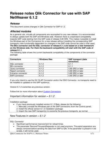
Section 2:MX 64TM ConnectorsSingle Row SealednConnector features–n1x2, 1x3, 1x4, 1x5, 1x6, 1x8––––––nAvailable in circuit sizesAdopted as the new USCAR single rowfootprintWill accommodate various terminal systems§ MX64§ Molex or Tyco GET§ Yazaki Kaisan1818-22 AWG and .36.36-.83 mm2 Metric WireCPA option4 polarization optionsMatte seal designCommon connector housing––Can accept any terminal housing designMolded circuit pegs can be left in during theMolex assembly process to seal voidedcircuits§ Eliminates separate rear seal cover0.64mm Connector Reference Manual - REV 11- September 27, 20047
Section 2:MX 64TM ConnectorsSingle Row SealedTerminalSpecificTPASingle Row ousingCommonPeripheralSealCommonMatte SealCommonCPA0.64mm Connector Reference Manual - REV 11- September 27, 20048
Section 2:MX 64TM ConnectorsSingle Row SealedSingle Row SealednCommon connector housing–––Eliminates separate rear seal coverCan accept any terminal housing designMolded circuit pegs can be left in duringthe Molex assembly process to sealvoided circuits.§ Allows for customer specific sealingpatterns0.64mm Connector Reference Manual - REV 11- September 27, 20049
Section 2:MX 64TM ConnectorsProduct IdentificationMOLEXPARTNUMBERDATE CODEXX XXXDAY of the year001 to 365YEAR (last 2 digits)0.64mm Connector Reference Manual - REV 11- September 27, 200410
Section 2:MX 64TM ConnectorsPart # legend single row sealed Female3140X3140X-X X X XSeal Cover Configurations 0,1,2,3,4,5,6,7,8,9CPA OPTION (0,1)0 Without CPA1 With CPAPolarization Options (1,2,3,4)1 USCAR Option A (BLACK)2 USCAR Option B (GRAY)3 USCAR Option C (BROWN)4 USCAR Option D (GREEN)5 USCAR OPTION B, COLOR: BLACK6 USCAR OPTION C, COLOR: BLACK7 USCAR OPTION D, COLOR: BLACKCircuit SIZE 2,3,4,5,6,8Terminal System 2,3,42 Tyco/Molex "GET"3 MOLEX 0.64mm4 Yazaki Kaisan0.64mm Connector Reference Manual - REV 11- September 27, 200411
Section 2:MX 64TM ConnectorsMolex MX64 0.64mmTyco/Molex “GET” 0.064mmYazaki Kaisan 0.64mm0.64mm Connector Reference Manual - REV 11- September 27, 200412
Section 2:TM ConnectorsMX 64Tyco/Molex GET 0.64mmFemale TerminalSeries 31402 Terminal Part NumbersOrientation TabFord Part NumberTyco Part NumberMolex Part Number18 & 20 AWG18 & 20 AWGTINTIN18 & 20 AWGTIN# 342300004# 3F2T3F2T-1447414474-RA# 13933661393366-1GOLD # 1L2T1L2T-1447414474-CAGOLD # 13933641393364-122 AWG22 AWGTINTIN# 3F2T3F2T-1447414474-SAGOLD #1L2T#1L2T-1447414474-DA# 13933671393367-1GOLD # 13933641393364-1GOLD # N/A22 AWGTIN# 342300002GOLD # N/A0.64mm Connector Reference Manual - REV 11- September 27, 200413
Section 2:MXTyco/Molex64TMGETConnectors0.64mm FemaleTerminalSeries 31402Orientation TabCorrect Orientation90 MisorientationLockLock-out180 MisorientationLockLock-outTerminal Insertion Orientation to Grommet Seal Cover0.64mm Connector Reference Manual - REV 11- September 27, 200414
Section 2:TM ConnectorsMX 64Molex 0.64mm FemaleTerminal Series 31403Series 31403 Terminal Part NumbersMOLEX Part Number18 & 20 AWGTIN# 3346833468-0003GOLD # 3346733467-000522 AWGTIN# 3346833468-0001GOLD # 3346733467-0003Orientation Tab0.64mm Connector Reference Manual - REV 11- September 27, 200415
Section 2:MX Molex64TMConnectors0.64mm FemaleTerminal Series 31403Orientation TabCorrect Orientation90 MisorientationLock-out180 MisorientationLock-outTerminal Insertion Orientation to Grommet Seal Cover0.64mm Connector Reference Manual - REV 11- September 27, 200416
Section 2:MXYazaki64TMConnectorsKaisan 0.64mm FemaleTerminal Series 31404Series 31404 Terminal Part NumbersYazaki Kaisan 0.64mm18 AWGTIN # 71167116-46194619-02AU # 71167116-46194619-0820 & 22 AWGTIN # 71167116-46184618-02AU # 71167116-46184618-08Orientation Tab0.64mm Connector Reference Manual - REV 11- September 27, 200417
Section 2:MXYazaki64TMConnectorsKaisan 0.64mm FemaleTerminal Series 31404Orientation TabCorrect orientation90 MisorientationLockLock-out180 MisorientationLockLock-outTerminal Insertion Orientation to Grommet Seal Cover0.64mm Connector Reference Manual - REV 11- September 27, 200418
Section 3Harness Assembly Instructions0.64mm Connector Reference Manual - REV 11- September 27, 200419
Section 3: Harness Assembly InstructionsA. TPA shown in “As-Shipped” position (FIG. 3-1)nnTPA shown “LOCKED” position (FIG. 3-2)TPA to remain in pre-lock position (as shipped) until all circuits areloaded (Fig. 3-1)TPAFig. 33-1Fig. 33-2Section Views of TPA in “Pre-Lock”and “Lock” Positions0.64mm Connector Reference Manual - REV 11- September 27, 200420
Section 3: Harness Assembly InstructionsTPA must be in prelock position to install terminals!AS SHIPPEDTPA in prelockn PHOTOTPA lockedn PHOTO0.64mm Connector Reference Manual - REV 11- September 27, 200421
Section 3: Harness Assembly Instructions2-3 way connectorsnnnTPA must be in pre-lock position to install terminals!If TPA is locked you must move it to the pre-lock position bycarefully lifting up on the upper side of the TPA using a 3.5 mm flatblade screw driver. This must be done as shown in FIG. 3-6DO NOT PRY ON THE LATCH SIDE OF THE CONNECTOR This willdamage the TPA and connector!Screw driverDO NOT PRY HERELIFT HEREFIG. 33-6FIG. 33-70.64mm Connector Reference Manual - REV 11- September 27, 200422
Section 3: Harness Assembly Instructions4-8 way connectorsnnnTPA must be in prelock position to install terminals!If TPA is locked you must move it to the pre-lock position bycarefully lifting up on the upper side of the TPA by inserting a 3.5mm flat blade screw driver into the TPA access window as shownDO NOT PRY ON THE LATCH SIDE OF THE CONNECTOR .This willdamage the TPA and connector!DO NOT PRY HEREScrew driverLIFT HERE0.64mm Connector Reference Manual - REV 11- September 27, 200423
Section 3: Harness Assembly InstructionsB. 0.64mm Terminal Installation (continued)nnWith TPA still in pre-lock position, orient terminal to rear of connector.Grip the wire, (Fig. 3-10) and insert through appropriate circuit opening (Fig.3-11). If resistance is encountered, retract the terminal and adjust the angle ofinsertion. Continue inserting the terminal until it stops and locks on the lockfinger with an audible click.Fig. 33-10Fig. 33-110.64mm Connector Reference Manual - REV 11- September 27, 200424
Section 3: Harness Assembly InstructionsD. Seating TPA with the 0.64mm TerminalnWith the terminals fully installed, the TPA can be seated into its final lockposition by applying an even force (Fig. 3-12) until it comes to a stop and youhear an audible click from the locking finger locking in place. If the TPAresists it may be detecting a partially installed terminal. Pull the TPA backinto its pre-lock position and make sure all terminals are fully installed. Uponcompletion, the TPA can be seated.Fig. 33-12 A&B0.64mm Connector Reference Manual - REV 11- September 27, 200425
Section 3: Harness Assembly InstructionsCompleted Product0.64mm Connector Reference Manual - REV 11- September 27, 200426
Section 4Connector Mating Instructions0.64mm Connector Reference Manual - REV 11- September 27, 200427
Section 4: Connector Mating InstructionsA.Connector polarization options & color identificationUSCAR Option A (BLACK)USCAR Option B (GRAY)USCAR Option C (BROWN)USCAR Option D (GREEN)Special request Option B,C& D (BLACK)For updated polarization options consult.HTTP://WWW.USCARTEAMS.ORG0.64mm Connector Reference Manual - REV 11- September 27, 200428
Section 4: Connector Mating InstructionsB. Connector matingnCorrectly orient the connector (align keying features) onto the matingconnector (Fig. 4-1) Then evenly push the connector onto the matingconnector until it locks with an audible click. (Fig. 4-2).Fig. 44-2Fig. 44-1AlignKeyingFeaturesAlignKeyingFeaturesMated connector0.64mm Connector Reference Manual - REV 11- September 27, 200429
Section 4: Connector Mating InstructionsC. Optional Connector Position Assurance (CPA)nWith the connector mated the CPA can now be engaged. Push the CPAtoward the mating surface until it clicks into its locked position (Fig. 4-3).CPAFig. 44-30.64mm Connector Reference Manual - REV 11- September 27, 200430
Section 5Service Instructions0.64mm Connector Reference Manual - REV 11- September 27, 200431
Section 5: Service InstructionsA. Connector removal from sensornTo un-mate the connector from the sensor, push the CPA (if equipped) awayfrom mating surface (Fig. 5-1) Then depress the latch on the top of theconnector so the lock releases.nGrip the connector and evenly pull straight away from the sensor. (Fig. 5-2)Fig. 55-1Fig. 55-20.64mm Connector Reference Manual - REV 11- September 27, 200432
Section 5: Service InstructionsB. TPA ServicingnStep 1: To add additional circuits move the TPA from locked to prelock as shown in section 3. Stop pulling when pre-lock is reached.nStep 2: To remove circuits that have been populated you must removethe TPA from the connector by raising it into pre-lock and thencontinue raising until the TPA has been removed.Fig. 55-3Step 1: Pry Up TPAFig. 55-40.64mm Connector Reference Manual - REV 11- September 27, 200433
Section 5: Service InstructionsB. TPA Servicing (continued)TPAViews of TPA in “Pre-Lock” Position0.64mm Connector Reference Manual - REV 11- September 27, 200434
Section 5: Service InstructionsE. 0.64mm Terminal RemovalnAfter removing the TPA, Push up on the wire and carefully displace thelocking finger using 1mm blade screwdriver. Once the locking finger hasbeen displaced gently pull on the wire to remove the terminal.nnDo not use excessive force. Excessive force can damage the lock finger.Once the required terminals have been removed, Replace the TPA and lock ifterminal population is complete.0.64mm Connector Reference Manual - REV 11- September 27, 200435
Section 5: Service InstructionsG. 0.64mm Terminal Removal (continued)nDo not use excessive force. Excessive force can damage the lockfinger.nDeflect the top of locking finger to unlock it from the terminal. Applylight pressure on lock finger while lightly pulling terminal wire.Screw driverSee page 36 forcross section viewLock FingerFemale TerminalFig. 55-90.64mm Connector Reference Manual - REV 11- September 27, 200436
Section 5: Service InstructionsF. 0.64mm Terminal Removal (continued)nCarefully displace the locking finger by prying the lock finger up tounlock it from the terminal. Use care not to over deflect the lock finger toavoid damage.Cross sectioned for photographic purposeInsert 1mmpry tool hereUnlock finger to remove terminal0.64mm Connector Reference Manual - REV 11- September 27, 200437
Section 5: Service InstructionsF. 0.64mm Terminal Removal (continued)nOnce the terminal lock finger is disengaged, pull on the wire (Fig. 512) to release the terminal.Fig. 55-120.64mm Connector Reference Manual - REV 11- September 27, 200438
Section 5: Service InstructionsG. MX0.64 Terminal CrimpingnIf the 0.64mm terminal needs to be replaced, a new one can be handcrimped using the Molex Crimp Tool Number 63811-4200. ContactMolex for terminal drawings, hand crimp instructions and crimpheight requirements.H. Tyco/Molex “GET” Terminal CrimpingnIf the Tyco/Molex “GET” terminal needs to be replaced, a newone can be hand crimped using the Molex crimp tool number .63811-4500 for the wire range: 0.22-0.35 mm2 & 22 awg. And63811-4600 for the wire range: 0.50-0.75 mm2 & 20-18 awg.Contact Molex for terminal drawings, hand crimp instructions andcrimp height requirements.I.Yazaki Kaisan terminal crimpingnIf the Yazaki Kaisan terminal needs to be replaced please consultYazaki for crimp tool information.0.64mm Connector Reference Manual - REV 11- September 27, 200439
Section 6: Testing of terminalsWhen testing the connector for continuity it is imperative that you do notdamage the terminals.Pogo pins should be checked for damage or sticking several times ashift to assure Containment if an issue is found.First a visual inspection of all the pins for damage should be performed.Next a testing block should depress all the pogo pins up into the barrel.If there is a bent or sticking pin it should get stuck up in the barreland must be replaced.Probing Damage can occur :If a sharp ended probe is inserted into the contact of the connector itmay damage the plating and increase contact resistance.If an oversize diameter probe is inserted into the terminal this will overdeflect the beam in the terminal and create an environment forintermittent connections and increased contact resistance.If a probe is inserted into the connector on an angle or off center it maydamage the terminal and/or connector.0.64mm Connector Reference Manual - REV 11- September 27, 200440
0.64mm Connector Reference Manual - REV 1- September 27, 2004 7 Section 2: MX 64TM Connectors Single Row Sealed n Connector features - Available in circuit sizes n 1x2, 1x3, 1x4, 1x5, 1x6, 1x8 - Adopted as the new USCAR single row footprint - Will accommodate various terminal systems § MX64 § Molex or Tyco GET § Yazaki Kaisan - 18-22 AWG and .36-.83 mm22 Metric WireMetric Wire