Transcription
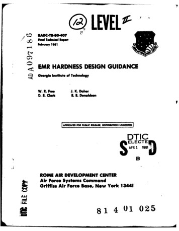
.LEVELFihNd Tedusewfbewy"1961EMR HARDNESS DESIGN GUIDANCEGoergia Intltut of TchnoloW. I. FreeD. 1. ClarkJ. K. DaherL 1. DonaldlsonDTICAPR 1 1381dSELECTEBSROME AIR DEVELOPMENT CENTERAir Force Systems CommandGriffiss Air Force Base, New York 13441FLU814 01 025
This repot has boon reviewed by the RAW Public Affairs Office (PA) andis releasable to the National Tecblical Information Service (NTIS).At NTiSitwill be releasable to the general public, Including foreign nations.RADC-TI-80-407 has been reviewed and is approved for publication.APPROVED:4p eJOHN H. EDWARDS, JR.Project EngineerAPPROVED:,VDAVID C. LUKE, Colonel, USAFChief, Reliability & Compatibility DivisionFOR THE X)AERJOHN P. RussActing Chief, Plans OfficeIf your address has changed or if you wish to be removed from the RADC mailing list,or if the addressee is no longer employed by your organization,please notify VADC (RBCA), Griffiss APB NY 13441. This will assist us inmsainteaining a current mailing list.Do not return this copy.Retain or destroy.
lk oUN CL ASSI FI EDSECURITY CLASSIFICATION OF THIS PAGE (When, SDatEnifed).A REPORT DOCMENTATION PAGE1.4.BEFORE COMPLETINGFORML.*CESINE CIPIENT2 CATAL.OG NUM§mERF2OP4WU-ADTITE anTYPE Of 111104DTSbttl,)64.TTLEdin'dSub i*)FinalEI4R HARDNESS DESIGN GUIDANCE *6Ar7IS.PERFORMING Olli.J.K. /,DaherF0027-C13lrkICY D.EE.E.3onaldsonPERFORMING ORGANIZATION NAME AND ADDRESSGeorgia Institute of TechnologyARA&WKUNT.811Engineering Experiment Station647F-O.PROGRAM1It. REPORT OATS/7I3. NUMBER asPAGESIA.MON 9. GAGENCY NAME 6 ADORSS0f djirnueoffC@IUlIGice)IS. SECURITY CLASS. (01u.4 fJfII .ISTIUUIONSTATEMENTELEMENT. PROJECT. TASKOFFICE NAME AND ADDRESSRome Air Development Center (RBCA)Griffiss AFB NY 13441r00-9C93& 29640306Atlanta GA 30332SfeRePORT osumkR--S. CONTRACT OR GRANT NUMSCORJ7' Au TWO(a)11I.CONTROLLING*flEREe.c-1A.-2358-FW.) R.r1ark9.* 111,0101jechnicalUNCLASSIFIED17a. -0tCLASSIFICATION/iDOWNGRADING(of th is Repave)Approved for public release; distribution unlimited17. DISTR18UTION STATEMENT (of th. ab.,,matoee in block 20. it different ftooRepo"f)SameIS.SUPPLEMENTARY NOTESRADC Project Engineer:It.John H. Edwards, Jr. (RBCA)KEY WOOI reaomAf an ,PW. sde of tuA@@ssad idetify by block number)Electromagnetic Radiation (EMR)EMR HardnessEMR Environment ForecastsEMR Design Handbook20.--AGSTRACT (Coentime anl rvr.041WIt 0104080InAir Launched HandbookAcquisition Cycleand idIfr1Vb lack n.m8f),This program was conducted to develop the overall methodology, guidelines,procedures, and guidance documentation required to establish an Air ForceEMRl hardness program for air launched ordnance systems. (The handbooktit e s "Management and Design Guidance Electromagnetic Radiation Hardnes 4.1r Air Launched Ordnance System", MIL-HDBK-335(USAF).)DO1473EO0ITION OF IHNOVSS6IS OSSOLETRUNCLASSIFIED3%96SECURITY CLASSIFICATION 01 THIS1PAGE 111040 Dat e w
UNCLASSIFIED39CURITY CLASS;PICATION OF THIS PAGECWh.Dagot-ud)IINCLASS! VIED 3CUI?CL &SSIVtCA*1011 00MAGEMPODate ,.rpledt
EVALUATIONThis final report summarizes a handbook on the design guidance for the hardening ofairborne weapon systems to electromagnetic energy. Even though the handbook is writtenfor airborne weapon systems, the application of the philosophy and management practicesas outlinedenvironmept.willapplyto allelectronic systems exposedtoan electromagneticAs the handbook will not have wide distribution, this report describes thehandbook with enough detail that those in the DOD who have interest can obtain thecomplete handbook.The handbook is well written and organized to provide completeprogram guidance for acquisition of all electronic weapon system. The handbook title is"Management and Design Guidance Electromagnetic Radiation Hardness for Air LaunchedOrdnance System," MIL-HDBK-335 (USAF), dated 15 January 1981.JOHN H. EDWARDS, JR.Project EngineerAccession ForNTIS GRA&IDTIC T ABlU:-t1:o'incedElJU-ti,'ctionDistribution/Avail bl ity CodesIAvail arid/orDistLpccialI.
PREFACEThis report was prepared by the Electronics Technology Laboratoryof the Engineering Experiment Station of the Georgia Institute of Technology on Contract No. F30602-79-C-0132.The work covered by thisreport was conducted under the general supervision of Mr. D. W. Robertson,Director, Electronics Technology Laboratory, Mr. H. W. Denny, Headof the Electromagnetic Compatibility Branch, and Mr. W. R. Free, Project Director.The report describes the objectives, activities, andresults of a program to develop an Air Force EMR hardness program forair launched ordnance systems.O--
IM HARDESDESIGN GUIDANCETABLE OF CONTENTS1. INTRODUCTION .2.1.1Background .1.2Program Objective and Scope.1.3Report Organization .1. . .1.1.2TASK 1 -- DEVELOPMENT OF CONCEPTS AND PROCEDURES FORESTABLISHING A CAPABILITY FOR GENERATING EMR ENVIRONMENTFORECASTS .32.1Task 1 -- Objectives and Scope .32.2The EMR Environment .32.32.42.52.6. . .2.2.1Life Cycle Phases and Mission Scenarios2.2.2Forecasting Requirements .2.2.3Preparation of EMR Environment Forecasts . . .455Requirements for EMR Environment Forecasts Duringthe Acquisition Cycle .62.3.1Conceptual Phase .62.3.2Full-scale Devel-'.mt.nt Phase .72.3.3Susceptibility/Vuinerability EvaluationPhase .7Organization and Procedures for Generating EMR.Environment Forecasts .8.8.82.4.1Method of Approach .2.4.2Preparing Organization .2.4.3Types of EMR Environment Forecasts .82.4.3.1Type I EMR Environment Forecast . .82.4.3.2Type II EMR Environment Forecast.92.4.3.3Type III FMR Enviroment Forecast.Current Status of the EMR Environment Forecasting.Capability .Task I Summary .ii.101112
TABLE OF CONTENTS (Concluded)Page3.TASK 2 -- DEVELOPMENT OF GUIDELINES AND PROCEDURES FORESTABLISHING, IMPLEMENTING, AND MANAGING AN EMR HARDNESSPROGRAM .133.1Task 2 Objective and Scope .133.2Study to Supplement EMR Susceptibility Data. .133.3Study to Develop EMR Measurement Techniques. .143.4Study to Develop EMR Prediction and Analysis. .Techniques .15Study to Develop Guidelines for Tailoring Specifications and Standards for EMR Hardness Programs . . .16Study to Develop a Recommended Outline for EMRHardness Program Plans .17TASK 3 -- DEVELOPMENT EMR HARDNESS MANAGEMENT AND DESIGNHANDBOOKS .204.1Task 3 -- Objective and Scope .204.2Final EMR Hardness Management and Design Handbook3.53.64.5.SUMMARY AND RECOMMENDATIONS .iv. .2023
1. INTRODUCTIONThe purpose of this report is to describe the activities, accomplishments, and results of a program to develop an Air Force EMR hardness program for air launched ordnance systems.1.1 Background. Air launched ordnance systems are exposed toa wide variety of high intensity electromagnetic environments in theperformance of their missions. These environments result from electromagnetic radiation (EMR) from a large number of sources including friendlyand hostile radars, radio transmitters, hostile jammers, etc. Thepotential vulnerability to these environments cannot be ignored inthe design and development of new air launched ordnance systems.To ensure that adequate consideration is given to EMR hardnessin the design and development stages of a new system, it is necessarythat an EMR hardness program for the system be established early inthe acquisition cycle and implemented throughout the acquisition cycle.1.2Program Objective andScope.The objective of this programwas to develop the overall methodology, guidelines, procedures, andguidance documentation required to establish an Air Force EMR hardnessprogram for air launched ordnance systems. The program was dividedinto three major tasks. The objective of Task 1 was to develop conceptsand recommendations for establishing an organization to provide thecapability for generating EMR environment forecasts and to work withRADC and Electromagnetic Compatibility Analysis Center (ECAC) personnelin establishing such a capability. In addition, this task includedthe development of specific information on how to request EMR environment forecasts, what input information is required for requests, andhow the forecasts are to be used in establishing EMR hardness requirements for a specific system.The objective of Task 2 was to develop detailed guidelines andprocedures for implementing specific portions of the EMR hardness program. The results from this task were used to prepare sections oftext and appendices for inclusion in the final EMR hardness management
and design handbook describing in detail how to implement criticalportions of an ER hardness program.The objective of Task 3 was the development of EMR hardnessmanagement and design handbooks to provide program managers, systemdesigners, and test personnel with detailed guidance for implementingan EMR hardness program throughout the life cycle of a system.ThisThe initial effort was directedtask included two distinct efforts.to the development of an interim handbook to provide interim guidanceinformation in a short time frame for use until more comprehensivedocumentation was available.This interim handbook was completedfour months after the initiation of the program and was submittedas Interim Technical Report No. 1 in August 1979.The second effortunder this task was the development of a final EMR hardness managementand design handbook which includes the information, procedures andguidelines developed under Task 1 and Task 2.This handbook is intendedto serve as a complete information source on EMR hardening and addressesall of the requirements that may be encountered in establishing andimplementing an EMR hardness program.The final handbook is beingsubmitted concurrently with this report under separate cover.1.3Report Organization.The material in the remainder ofthis report is divided into four major sections.Section 2 describesthe Task 1 effort of the program in establishing a capability forgenerating EMR environment forecasts.Section 3 describes the Task 2effort of the progam in developing guidelines and procedures forimplementing and managing an EMR hardness program.Section 4 describesthe Task 3 effort of the program in developing EMR hardness managementand Design Handbooks.Section 5 summarizes the current status ofthe Air Force EMR Hardness Program and recommends areas in whichadditional work is needed.2
2.TASK 1 -- DEVELOPMENT OF CONCEPTS AND PROCEDURES FOR ESTABLISH-ING A CAPABILITY FOR GENERATING EMR ENVIRONMENT FORECASTS.2.1Task 1 -- Objectives and Scope.The objectives of Task 1were to define the requirements for EMR environment forecasts, to assist RADC and ECAC in establishing a capability for generating EMRenvironment forecasts, and to develop guidelines and procedures forutilizing EMR environment forecasts in establishing the EMR hardness.squirements for air launched ordnance systems.The task includedthe following efforts:(1) Identify the points in the acquisition cycle at which EMRenvironment forecasts are required;(2) Provide recommendations to ECAC as to the type, scope, levelof detail, and the format for each environmental forecast;(3) Assist ECAC in devloping guidelines and procedures for requestingEMR environment forecasts; and(4) Develop guidelines and procedures for utilizing EMR environme . "orecasts to establish EMR hardness requirements.2.2The EMR Environment.The initial objective of this taskwas to define the electromagnetic environments that air launched ordnance systems will be exposed to during the accomplishment of theirintended missions.The electromagnetic environment incident on anair launched ordnance system results from the electromagnetic radiation(EMR) from a number of radiating sources in the vicinity of the system.The radiating sources may include friendly and/or hostile radars, radiotransmitters, jammers, and other relatively high power radiating systems.These radiating sources may be located on the ground, on groundvehicles, on ships, or on aircraft.The spectral distribution of theradiated energy in the electromagnetic environment (EME) is determinedby the operating frequencies of the radiating sources.The levelsof the EME are determined by the amount of power being radiated bythe individual sources, the distance between the weapon system andthe individual radiating sources, and the orientation of the weaponsystem relative to the radiation pattern of the individual sources.
While the system is mounted on a delivery aircraft, the radiation from electronic systems (such as radars, jammer pods, and communications transmitters) on board the dpUvery aircraft will be a primarysource of the FME incident on the weapon system.If the delivery air-craft is flying in a formation, the radiation from escort aircraftmay be a primary source of the EME incident on the weapon system.While the system is in free flight between the delivery aircraft anda target, the radiation from the ground environment may be a primarysource of the EME.As the system approaches a target, the radiationfrom the target itself and emitters in the vicinity of the target willprobably be the major source of the EME.2.2.1Life Cycle Phases and Mission Scenarios.An air launchedordnance system will be exposed to several different EMR environmentsduring its life cycle.Thus, to define the EMR environment a systemis to be hardened to, it is necessary to define each of the independent environments to which the system will be exposed.These indi-vidual environments include the ground environment, the cosite environment, the intersite environment, and the approach-to-target environment.The ground environment includes the radiation from all emit-ters (friendly and hostile) on the ground (and on water) over whichthe system will travel (both on the delivery aircraft and in free flight)in the performance of its missions.The cosite environment includesthe radiation from emitters on-board the delivery aircraft.The inter-site environment includes the radiation from emitters on escort aircraft,other friendly aircraft, and hostile aircraft.The approach-to-targetenvironment includes the radiation from the target and emitters inthe vicinity of the target.After the individual environments havebeen defined, each of the environments must be projected into the futureby forecasting techniques to be representative of the environmentsthe system will be exposed to at the end of its service life.In order to establish the overall EMR hardness requirements fora system, it is necessary to integrate the forecasted individual environments into a composite EMR environment profile which indicates themaximum radiation levels that the system will be exposed to duringits life cycle.
2.2.2Forecasting Requirements.In defining the EMR environmentsa system will be exposed to during deployment, consideration must begiven to the fact that the system will probably be in development forseveral years, and, in addition, the system will probably have an inservice life spanning several years.Hence, it is not sufficient tojust define the EMR environments that exist at the present time; itis necessary to predict the EMR environments the system will be exposedto during deployment until the end of its in-service life.For EMRenvironment definitions used in the early stages of a system development, the environment definitions will have to be projected by forecasting techniques to a time frame which is the sum of the acquisitioncycle and the in-service life cycle of the system in the future.Asthe development of the system progresses the projection time for theupdated EMR environment definitions will be reduced.If it is assumedthat the acquisition time of a typical system is 10 years and the average in-service life is 15 years, the initial EMR environment definitionswould need to be projected by a 25-year forecast.Environment defini-tions used midway in the acquisition cycle would need to be projectedby 20 years, while the environments used at the end of the acquisitioncycle would need to be projected 15 years.2.2.3Preparation of EMR Environment Forecasts.The generationof an EMR environment forecast for a proposed air launched ordnancesystem is a complex and difficult process requiring extensive information describing the operational characteristics and geographical locations of friendly and hostile emitters world wide.The generationof EMR forecasts also requires extensive culling and processing ofthe emitter data and the application of validated forecasting techniques.While the operational EMR environment forecasts for each systemmust be tailored for that specific system, the procedures and forecasting techniques for generating the EMR forecasts will be essentiallythe same for all systems.In addition, the generation of an EMR fore-cast fo- a specific system will entail processing the same EMR database to tailor an environment to the operational and tactical requirements of the specific system.5. . .
Under these conditions, it is not reasonable to require each program office to generate the EMR forecasts for the system for whichit is responsible.This would require each program office to establishan extensive EMR data base and develop the organization, procedures,and forecasting techniques for generating EMR forecasts.A much moreefficient approach is to assign a permanent organization the responsibility for satisfying the EMR environment forecast requirements forall program offices.With this approach, the basic EMR data base,the processing procedures, and the forecasting techniques are onlydeveloped one time, eliminating duplication of efforts.The Electromag-netic Compatibility Analysis Center at Annapolis, Maryland was designated as the organization responsible for providing EMR environmentforecasts for Air Force programs.2.3Requirements for EMR Environment Forecasts During the Acquisi-tion Cycle.Another objective of this task was to define the pointsin the acquisition cycles of air launched ordnance systems at whichEMR envionment forecasts are required.It was concluded from a studyof the acquisition process that a minimum of three EMR environmentforecasts are required.The actual total number of forecasts requiredwill depend on the complexity of the system being developed and thetime duration of the acquisition cycle.For a large complex systemrequiring an unusually long acquisition time frame, several EMR forecasts may be necessary.The three points in the acquisition cycle at which the requirements for EMR environment forecasts are most critical were identifiedas:(1) the initiation of the conceptual phase, (2) during the prepara-tion of the RFP documentation for the full scale development phase,and (3) during the system susceptibility/vulnerability evaluation phase.For large complex systems with extended acquisition periods, additionalEMR forecasts may be required at the initiation of the validation phaseand at the initiation of the production phase.2.3.1Conceptual Phase.The first EMR environment forecast should.be available for use during the selection and evaluation of alternateconcepts for satisfying the Statement of Need (SON) document.6This
EMR environment definition should be used in feasibility analyses,trade-off studies of alternate approaches and concepts, and the definition of risks.This initial EMR forecast should also be used by the program manager and the EMCAB to establish budgets, schedules, and resources requirements for inclusion in the EMR Hardness Program Plan and the Testand Evaluation Master Plan.2.3.2Full-scale Development Phase.A second updated EMR environ-ment forecast should be available for use during the preparation ofthe Request for Proposal (RFP) documentation for the full-scale development phase of a program.This EMR forecast should be incorporatedinto the RFP to convey to the bidders the amount of EMR hardness thatwill be required.The forecast should also be used to tailor the limitsand test procedures of any EMC specifications and standards (such asMIL-E-6051, MIL-STD-461, and MIL-STD-462) which will be invoked bythe contract.This EMR environment forecast should also be used by the selectedcontractor to establish the EMR hardness criteria for the design ofthe full scale engineering development model of the system.In addi-tion, the EMR forecast should serve as a basis for the contractor'sEMR Hardness Control Plan and the EMR Hardness Test Plan.2.3.3Susceptibility/Vulnerability Evaluation Phase.A thirdEMR environment forecast should be available for use during the susceptibility/vulnerability evaluation phase of a program.This forecastshould be used by the system EMR test organization as guidance in conducting the system EMR susceptibility tests and as the threat definition in vulnerability analyses.The information contained in thisforecast and the format should be such that the critical frequencyranges and modulation characteristics can be identified for systemsusceptibility test purposes.In addition, the format should be suchthat EMR environment profiles for specific mission scenarios can begenerated for vulnerability analyses.7
2.4Organization and Procedures for Generating EMR EnvironmentForecasts.2.4.1Method of Approach.As previously discussed in Section 2.2.3,it was concluded that the most efficient approach for generating EMRenvironment forecasts is to assign a permanent organization the responsibility for satisfying the EMR environment forecast requirements forall program offices developing air launched ordnance systems.2.4.2The Electromagnetic CompatibilityPreparing Organization.Analysis Center (ECAC) located at Annapolis, Maryland has been designated as the organization responsible for satisfying the EMR environment forecast requirements for Air Force air launched ordnance systems.This center is a joint-service Department of Defense facility, established to provide rapid analysis of electromagnetic compatibility problems of the military services.ECAC has an extensive electromagneticenvironmental data base which includes a comprehensive listing of existing electromagnetic emitters throughout the world.In addition, ECAChas access to the required intelligence information and has extensiveexperience as to which organizations are the best sources of particulartypes of information.ECAC also has considerable experience in generat-ing electromagnetic environmental profiles, similar to those of currentinterest, in support of RADC's HAVE NOTE test programs.2.4.3Types of EHR Environment Forecasts.While the objectiveof all EMR forecasts is the same (i.e., to define the anticipated operational electromagnetic environment of the system), the manner in whicheach forecast will be used, the stage of development of the systemwhen each forecast is generated, and the extended time periods betweenforecasts dictate that the EMR forecasts obtained at different pointsin the acquisition cycle of a system will be dtfferent.Since EMRforecasts are required at three different points in the acquisitionprocess, three different types of forecasts are required.2.4.3.1Type I EMR Environment Forecast.The initial EMR fore-cast for use at the beginning of a program will be based on a Type I8
analysis.It is anticipated that at this stage of the program thesystem will be largely or entirely conceptual and little, if any, operational and tactical information, as well as performance specifications,for the system will have been defined.Thus, the Type I analysis tech-nique must be capable of providing an EMR environment forecast witha minimum amount of input data.For example, if the theater(s) ofoperation has not been defined, then a worldwide environment shouldbe considered in the analysis.If the type(s) of delivery aircrafthas not been defined, then the worst-case, on-board environment forthe class of aircraft which could serve as a delivery platform shouldbe considered in the analysis, etc.The total life cycle of a typical system from the initiation ofthe conceptual phase to the final phasing out of the system from theinventory is estimated to be approximately 30 years.Thus, in theabsence of specific information to the contrary, the Type I EMR environment should be forecasted for a 30 year period.It is realized that the absolute accuracy of a Type I EMR environment forecast based on a minimum amount of operational input dataand forecasted over a 30-year period is highly questionable.However,this type of data will be extremely useful at the beginning of a program in performing feasibility analyses and trade-off studies of alternate approaches and concepts.In addition, this coarse EMR environmentdata will serve as a useful basis for establishing budgets, schedules,and resources requirements for the EMR hardness program and the EMRtest program.2.14.3.2Type II EMR Environment Forecast.It is anticipatedthat in the development of a typical air launched ordnance system,a second updated (Type II) EMR environment forecast will be obtainedfor use in preparing the RFP documentation for the full scale development phase of the program.At this phase of the acquisition cycle,it is assumed that a great deal of the operational and tactical information for the proposed system will have been defined, and the desiredperformance specifications will have been defined.Specifically, thetheater(s) of operation will have been defined, the type(s) of deliveryaircraft (and possibly the location of the weapon on the aircraft)9
will have been determined, and the specific classes or types of targetsthe weapon will be used against will have been established.Also,a 20-year foreca3ting period is considered adequate for a system atthis stage of development.Under these conditions, the Type II EMR environment forecast shouldbe a far more accurate description of the actual operational EMR environment of the proposed system.The ground environments will be restrictedto the actual theaters of operation and the on-board environment willbe restricted to the specific delivery aircraft.The Type II analysis technique must be capable of providing anEMR environment forecast with sufficient information so that when theforecast is incorporated into the RFP for the full scale developmentprogram it conveys to the bidders realistic EMR hardness requirementsfor the proposed system.In addition, the format of the Type II EMRforecast should be designed so that the selected contractor can readilyuse the forecast in establishing his EMR hardness design criteria forthe proposed system.The selected contractor also must be able touse the Type II EMR forecast as the basis for his EMR Hardness ControlPlan and his EMR Hardness Test Plan.2.4.3.3Type III EMR Enviroment Forecast.It is anticipatedthat a third updated (Type III) EMR environment forecast will be obtainedfor use during the susceptibility/vulnerability testing of the fullscale development model and the production model of the system.ThisEMR forecast will be obtained near the completion of the full scaledevelopment mcdel of the system.At this stage of the acquisitioncycle, it is assumed that all operational, tactical, and performancespecifications for the system will have been completely defined.A15-year forecasting period is considered adequate for a system at thisstage of development.Under these conditions, the type III EMR environ-ment forecast should be an accurate description of operational EMRenvironment the system will encounter until the end of its servicelife.The format of the Type III EMR forecast should be designed toprovide maximum support to both the development of system susceptibility tests and the development of system vulnerability analyses.10
The format should be such that critical frequency ranges and modulation characteristics can be identified for system susceptibility testsand that EMR environment profiles for specific mission scenarios canbe generated for vulnerability analyses.2.5Current Status of the EMR Environment Forecasting Capability.The Electromagnetic Compatibility Analysis Center (ECAC) has developeda capability to rapidly generate current (baseline) and future (forecasted) EMR environment profiles that are tailored to both the acquisition and deployment phases of air launched ordnance systems.The com-plete capability, designated the DoD/ECAC Environmental DefinitionSystem fEDS), was developed under a project entitled "Tailored EMRHardness Criteria" sponsored by the Rome Air Development Center (RADC).ECAC is currently publishing a 5-volume report describing theEnvironment Definition system and the procedures for requesting EMRenviornment forecasts.The report is entitled "Environmental Defini-tion System (EDS)" and the report number is ESD-TR-80-100-(Vols 1-5).The EDS consists of a series of manual and computerized models,software support packages, and administrative procedures which canbe used to define the current or the future EMR environment an airlaunched ordnance system will be exposed to in accomplishing its missions.The EDS consists of two parts.The first part, called theGround Environment Definition System (GEDS), was designed to generatecurrent and future EMR environment profiles resulting from ground basedemitters.The second part, called the Aircraft Environment DefinitionSystem (AEDS), was designed to generate current and future EMR environment profiles resulting from aircraft based emitters.The GEDS isused to generate the ground environment profiles; and the AEDS is usedto generate the aircraft cosite, aircraft intersite, immediately afterlaunch, and final app
EMR HARDNESS DESIGN GUIDANCE Goergia Intltut of Tchnolo W. I. Free J. K. Daher D. 1. Clark L 1. Donaldlson DTIC SELECTEAPR 1 1381d B ROME AIR DEVELOPMENT CENTER S Air Force Systems Command Griffiss Air Force Base, New York 13441 FLU 814 01 025.
