Transcription
UL Evaluation ReportUL ER10167-02Issued: August 8, 2016Revised: February 28, 2022Visit UL’s Product iQ database for current status of Report.UL Category Code: ULFBCSI MasterFormat DIVISION:Sub-level 2:Sub-level 3:Sub-level 4:07 00 00 THERMAL AND MOISTURE PROTECTION07 50 00 – Membrane Roofing07 54 00 – Thermoplastic Membrane Roofing07 54 19 – Polyvinyl-Chloride RoofingCOMPANY:Johns Manville717 17th St.Denver, CO 80202-3330 USAwww.jm.com1. SUBJECT:JM PVC 50 mil, JM PVC 60 mil, JM PVC 80 milJM PVC Fleece Backed 50 mil, JM PVC Fleece Backed 60 mil,JM PVC Fleece Backed 80 milJM PVC SD Plus 50 mil, JM PVC SD Plus 60 mil, JM PVC SD Plus 80 mil2. SCOPE OF EVALUATION 2021, 2018, 2015, 2012, 2009 and 2006 International Building Code (IBC) 2021, 2018, 2015, 2012, 2009 and 2006 International Residential Code (IRC) ICC ES Acceptance Criteria for Roof-Covering Systems (AC75), Dated July 2010 (Editorially revisedApril 2021) ICC ES Acceptance Criteria for Quality Documentation (AC10), Dated January 2019Page 1 of 39
The products were evaluated for the following properties: Roofing Systems for Exterior Fire Exposure (UL 790, ASTM E108) Roofing Systems, Wind Uplift Resistance (FM 4474, UL 1897) Physical Properties (ASTM D4434, ASTM G154) Foot Traffic Resistance (FM 4470)3. REFERENCED DOCUMENTS UL 790, Standard Test Methods for Fire Tests of Roof CoveringsUL 1256, Standard Fire Test of Roof Deck ConstructionUL 1897, Uplift Tests for Roof Covering Systems, Sixth EditionASTM D4434, Standard Specification for Poly (Vinyl Chloride) Sheet RoofingASTM E108, Test Methods for Fire Tests of Roof CoveringASTM G154, Standard Practice for Operating Fluorescent Light Apparatus for UV Exposure ofNonmetallic MaterialsFM 4470, Single-Ply, Polymer-Modified Bitumen Sheet, Built-Up Roof (BUR) and Liquid Applied RoofAssemblies for use in Class 1 and Noncombustible Roof Deck ConstructionFM 4474, Evaluating the Simulated Wind Uplift Resistance of Roof Assemblies Using Static Positiveand/or Negative Differential PressuresICC ES Acceptance Criteria for Membrane Roof-Covering Systems (AC75), Dated July 2010(Editorially revised April 2021)ICC ES Acceptance Criteria for Quality Documentation (AC10), Dated January 20194. USESJM PVC, JM PVC Fleece Backed and JM PVC SD Plus membranes are single-ply membranes used asroof coverings in mechanically fastened or fully adhered Class A, B or C roof assemblies installed oncombustible or non-combustible roof decks.5. PRODUCT DESCRIPTIONJohns Manville PVC membranes are reinforced single ply polyvinyl chloride (PVC) membranes designedto be used in adhered roofing systems or mechanically fastened roofing systems as described in this report.The membranes are provided in rolls of various lengths and widths.These roofing systems consist of the single-ply PVC roofing membrane, insulation where used, barrierboard or slip sheet where used, flashing, mechanical fasteners, and adhesives that are installed on acombustible or non-combustible roof deck.These roofing assemblies incorporating the membranes comply with the following properties when installedas described in this report.Fire Classification: Roofing assemblies covered under this report have been tested for fire classificationClass A, B or C in accordance with UL 790 or ASTM E108, as required by Section 1505.1 of the IBC andSection R902.1 of the IRC.Page 2 of 39
Wind Resistance: Roofing assemblies covered under this report have been tested for wind upliftresistance in accordance with FM 4474 and UL 1897, and therefor qualify for use under Roofingmembranes Section 1504.4.1 of the 2021 IBC and Section 1504.3.1 of the 2018, 2015, 2012, 2009 and2006 IBC.The roofing assemblies shall be designed to resist the design wind load pressures for components andcladdings in accordance with Section 1609 of the IBC and Section R905.1 of the IRC.Physical Properties: The roofing membranes covered under this Report have been tested for physicalproperties in accordance with ASTM D4434 and ASTM G154, and therefore qualify for use under Section1507.12.2 and Section 1504.7 of the 2021 IBC and Section 1507.13.2 and Section 1504.6 of the 2018,2015, 2012, 2009 and 2006 IBC and Section R905.13.2 of the IRC.Impact Test: The single-ply roofing membranes covered under this Report have been tested for impactresistance in accordance with “Resistance to Foot Traffic Test” in Section 5.5 of FM 4470 and thereforequalify for use under Section 1504.8 of the 2021 IBC and Section 1504.7 of the 2018, 2015, 2012, 2009and 2006 IBC.5.15.2Membranes:5.1.1JM PVC (50, 60, 80 mil) are membranes having a proprietary thermoplastic formulationconsisting of PVC resins, plasticizers, stabilizers, biocides, flame retardants, U.V.absorbents with DuPont Elvaloy KEE which incorporate a polyester scrim that islaminated between two layers of PVC film giving the membrane strength and durability.5.1.2JM Fleece Backed (50, 60, 80 mil) are JM PVC membranes combining its proprietarythermoplastic formulation with DuPont Elvaloy KEE. These membranes aremanufactured with a spunbond 3.8 oz. polyester fleece back mat bound to the underneathside of the membrane for enhanced adhesion characteristics.5.1.3JM PVC SD Plus (50, 60, 80 mils) are membranes having a proprietary thermoplasticformulation consisting of PVC resins, plasticizers, stabilizers, biocides, flame retardants,U.V. absorbents which incorporate a polyester scrim that is laminated between two layersof PVC film giving the membrane strength and durability.Insulation:Foam plastic insulation when used shall have a flame spread index of not more than 75 whentested at the maximum thickness intended for the use in accordance with UL 723 or ASTM E 84.To qualify for use under Section 2603.3 and Exception 3 of the IBC of the 2021, 2018 and 2015IBC or under Section R906.1 of the 2021 IRC the foam plastic insulation when installed as part ofa Class A, B or C roof-covering system, provided the assembly complies with UL 1256. To qualifyfor use under Section 2603.3 and Exception 3 of the 2012, 2009 and 2006 IBC or Section R906.1of the 2018, 2015, 2012 and 2009 IRC the foam plastic insulation when installed as part of a ClassA, B or C roof-covering assembly, provided the assembly complies with FM 4450 or UL 1256. Toqualify for use under Section 2603.4.1.5 of the 2021, 2018 and 2015 IBC, a thermal barrier is notrequired for foam plastic insulation that is part of a Class A, B or C roof-covering assembly, providedthe assembly with foam plastic insulation complies with UL 1256. To qualify for use under Section2603.4.1.5 of the 2012, 2009 and 2006 IBC, a thermal barrier is not required for foam plasticinsulation that is part of a Class A, B or C roof-covering assembly, provided the assembly with foamplastic insulation complies with FM 4450 or UL 1256.Page 3 of 39
5.3Fasteners:Fasteners used to mechanically fasten insulation and membranes to the roof deck shall becorrosion resistant and shall be one of the fasteners identified in the Appendix of this Report.5.4Adhesive:The adhesive used for adhering John Manville PVC membranes to the insulation or roofingsubstrate shall be as noted in the Appendix of this Report.5.5Asphalt:Hot roofing asphalt, when specified in the roofing assemblies shall conform to ASTM D312,Type IV.6. INSTALLATIONJohn Manville single ply PVC membranes shall be installed in accordance with the applicable code, thisreport and the manufacturer’s published installation instructions. The membranes shall be installed inaccordance with Section 1507.12 of the 2021 IBC, Section 1507.13 of the 2018, 2015, 2012, 2009 and2006 IBC or Section R905.13 of the IRC as applicable, except as noted in this report.The manufacturer’s published installation instructions shall be available at all times on the jobsite duringinstallation.The slope of the roof on which the membranes are installed shall be a minimum of 1/4:12 (2% slope) andshall not be more than the maximum slope indicated in Tables of this Report.Penetrations and terminations of the roof covering shall be flashed and made watertight in accordance withthe requirements of the membrane manufacturer, Section 1503.2 of the IBC or Section R903.2 of the IRCand applicable code.7. Fire Classification7.1New Construction: Roof assemblies utilizing JM PVC (50, 60, 80 mil), JM Fleece Backed (50,60, 80 mil) and JM PVC SD Plus (50, 60, 80 mil) single ply PVC roof coverings are described in ULCertification Category for Roofing Systems, (TGFU), under File R10167 and in Tables in thisReport.7.2Reroofing: The existing roof shall be inspected in accordance with the provisions and limitationsof Section 1512 of the 2021 IBC, Section 1511 of the 2018 IBC, Section 1510 of the IBC or SectionR908 of the 2021 and 2018 IRC or Section R907 of the 2015, 2012, 2009 and 2006 IRC, asapplicable. The existing deck shall be inspected to verify that the structure to be reroofed isstructurally sound and adequate to support and secure the roofing membrane. Prior to installationof new roof coverings, inspection by and approval from the code official having jurisdiction isrequired.Johns Manville PVC membranes may be installed over existing Classified Class A, B or C roofingsystems as described in the UL Certification Category for Roofing Systems (TGFU), File R10167under the heading Maintenance and Repair Systems (PVC) for applicable coverage and details ofthe roof assemblies and in Tables in this Report.Page 4 of 39
Class A, B or C roof coverings may be installed over existing classified roof assemblies under thefollowing conditions without additional roof classification tests, provided the resulting classificationis the lower of the new and existing roof classifications under the following conditions: New uninsulated roof coverings installed only over existing uninsulated assemblies. New insulated roof coverings installed over existing uninsulated assemblies only.8. Wind Resistance8.1New Construction: The allowable wind uplift pressures for the roof assemblies are noted in theTables in this Report. Metal edge securement for all systems shall be designed in accordance withANSI/SPRI ES-1, complying with Section 1504.6 of the 2021 IBC or Section 1504.5 of the 2018,2015, 2012, 2009 and 2006 IBC. For certifications of metal edge securement systems inaccordance with ANSI/SPRI ES-1, See UL’s Product iQ database Roof-edge Systems, Metal forUse with Low-slope Roofing Systems (TGJZ).8.2Reroofing: Roof covering systems employing mechanical fasteners shall be qualified, to thesatisfaction of the code official, as to the adequacy of fasteners penetrating through existing roofcoverings into structural substrates. Since the composition and/or conditions of any particularunderlying existing roofing materials may vary and reroofing material may vary, reroofing withadhered systems is outside the scope of this report.9. CONDITIONS OF USEThe Johns Manville single ply PVC roofing membranes described in this Report comply with, or are suitablealternatives to, what is specified in those codes listed in Section 2 of this Report, subject to the followingconditions:9.1Materials and methods of installation shall comply with this Report and the manufacturer’spublished installation instructions. In the event of a conflict between the installation instructionsand this Report, this Report governs.9.2Johns Manville single ply PVC roofing membranes shall be installed by professional roofingcontractors trained and approved by the manufacturer.9.3See UL’s Product iQ database Roofing Systems (TGFU) File R10167. Also refer to the Tablesof this Report.9.4Above-deck thermal insulation board shall comply with the applicable standards listed in Table1508.2 in Section 1508.2 of the IBC or Table R906.2 in Section R906 of the IRC.9.5Wind uplift pressures on any roof area, including edges and corner zones shall not exceed theallowable wind pressure for the roof covering installed in that particular area. Refer to the Tablesin this Report.9.6For assemblies containing mechanical attachment for the perimeter and corner roof zones 2 and3, the attachment density may be increased by a qualified design professional, as necessary, tomeet the design pressure requirements in these areas.9.7The allowable wind uplift pressures listed in the Tables of this Report are for the roof systems only.The deck and framing to which the roofing system is attached shall be designed for the applicablecomponents and cladding, wind loads in accordance with the applicable codes.Page 5 of 39
9.8When application is over an existing roof, documentation of the wind uplift resistance of thecomposite roof construction shall be submitted to the code official.9.9The metal edge securement shall be designed and installed for wind loads in accordance withChapter 16 of the IBC and tested for resistance in accordance with Test Methods RE-1, RE-2 andRE-3 of ANSI/SPRI ES-1. The basic wind speed, V, shall be determined from Figures 1609.3(1)through 1609.3(12) of the 2021 IBC or Figures 1609.3(1) through 1609.3(8) of the 2018 IBC asapplicable. The ultimate wind speed, Vult wind speed shall be determined from Figures 1609.3(1)through 1609.3(3) of the 2015 IBC or Figure 1609A, 1609B, or 1609C of the 2012 IBC as applicable.The basic wind speed shall be determined from Figure 1609 of the 2009 and 2006 IBC asapplicable. The ultimate design wind speed shall be determined from Figures R301.2(2) andR301.2.1.1 of the 2021 IRC or Figures R301.2(5)A and R301.2(5)B of the 2018 IRC or FiguresR301.2(4)A and R301.2(4)B of the 2015 IRC. The basic wind speed shall be determined fromFigures R301.2(4)A through R301.2(4)C of the 2012 IRC as applicable or Figure R301.2(4) of the2009 and 2006 IRC.9.10The Johns Manville PVC single ply membranes covered under this report are produced under theUL LLC Classification and Follow-Up Service Program, which includes audits in accordance withquality elements of ICC-ES Acceptance Criteria for Quality Documentation, AC 10.10. SUPPORTING EVIDENCE10.1Data in accordance with ICC-ES Acceptance Criteria for Membrane Roof-Covering Systems,AC75.10.2Manufacturer’s descriptive product literature, including installation instructions.10.3UL Classification Reports in accordance with UL 790. See UL Product Certification Category underFile R10167 for Roofing Systems (TGFU).10.4Data in accordance with UL 1897.10.5Data in accordance with FM 4474.10.6Data in accordance with FM 4470.10.7Data in accordance with ASTM D4434 and ASTM G154.10.8Documentation of quality system elements in accordance with ICC-ES Acceptance Criteria forQuality Documentation, AC10.11. IDENTIFICATIONThe Johns Manville PVC single ply membranes described in this evaluation report are identified by amarking bearing the report holder’s name (Johns Manville), the plant identification, the product designation,the UL Classification Mark, and the evaluation report number UL ER10167-02. The validity of the evaluationreport is contingent upon this identification appearing on the product or UL Classification Mark certificate.12. USE OF UL EVALUATION REPORT12.1 The approval of building products, materials or systems is under the responsibility of the applicableauthorities having jurisdiction.12.2 UL Evaluation Reports shall not be used in any manner that implies an endorsement of the product,material or system by UL.Page 6 of 39
12.3 The current status of this report, as well as a complete directory of UL Evaluation Reports may befound at UL.com via our UL’s Product iQ database:UL Evaluation ReportsPage 7 of 39
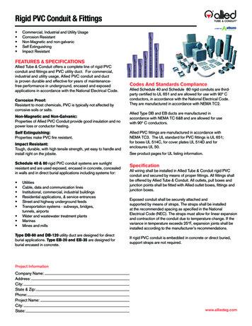
lConcreteStructuralConcreteStructural CementBoardStructural CementBoardPoured GypsumDeckPoured icationDescriptionNew or ExistingAdhered Assemblies over Concrete DeckNew or ExistingMechanically Fastened Assemblies over ConcreteDeckNew, Existing orRecoverInduction Welded Assemblies over Concrete DeckNew or ExistingNew or ExistingAdhered Assemblies over Tectum I CementitiousWood Fiber PanelsAdhered Assemblies over Tectum I CementitiousWood Fiber PanelsNew or ExistingAdhered Assemblies over Poured Gypsum DeckNew, Existing orRecover10SteelNew or Existing11SteelNew, Existing orRecoverMechanically Fastened Assemblies over PouredGypsum DeckAdhered Lightweight Concrete Assemblies overConcrete DeckMechanically Fastened Assemblies over ConcreteDeckAdhered Lightweight Concrete Assemblies overSteelMechanically Fastened Lightweight ConcreteAssemblies over SteelRecoverAdhered Roof CoverRecoverMechanically Fastened Roof CoverRecoverInduction Welded Roof Cover789121314StructuralConcreteStructuralConcrete or SteelStructuralConcrete or Steel15Steel16Steel17Steel1819WoodWoodNew or ExistingNew, Existing orRecoverNew, Existing orRecoverNew, Existing orRecoverNew, Existing orRecoverNew or ExistingNew or ExistingPage 8 of 39Adhered Roof CoverMechanically Fastened Roof CoverInduction Welded Roof CoverMechanically Fastened Roof CoverInduction Welded Roof Cover
The following notes apply to the systems outlined herein:1. Roof decks shall be in accordance with IBC or IRC requirements to the satisfaction of the AHJ. Windload resistance of the roof deck shall be documented through proper codified and/or FBC Approvaldocumentation. Wind load resistance of the roof deck shall be documented through proper codifiedApproval documentation.2. Unless otherwise noted, fasteners and stress plates for insulation attachment shall be as follows.Fasteners shall be of sufficient length for the following engagements:Steel or Wood Deck: JM All Purpose Fasteners #14 or JM UltraFast Fastener #12 must penetratesteel decking a minimum 3/4-inch into the top flute of the steel deck or wood deck.Concrete Deck: JM All Purpose Fastener #14 minimum 1 inch embedment. Fasteners installed witha pilot hole in accordance with the fastener manufacturer’s published installation instructions.All Fasteners shall be FM Approved.3. Preliminary insulation attachment minimum five fasteners per 4 x 8 ft board or minimum four fastenersper 4 x 4 ft board.4. Unless otherwise noted, insulation adhesive application rates are as follows. Ribbon or bead width isat the time of application; the ribbons/beads shall expand as noted in the manufacturer’s publishedinstructions:Hot asphaltJM Urethane Insulation Adhesive:JM Two Part Urethane InsulationAdhesive:JM Roofing System Urethane Adhesive:Full coverage at 20 -25 lbs/sqContinuous 0.75-inch ribbons, 12-inch ocContinuous 0.75-inch ribbons, 12-inch ocContinuous 0.5 to 075-inch wide ribbons, 12-inch ocNote: When multiple layers(s) of insulation and/or coverboard are installed in ribbon-applied adhesive,adhesive ribbons shall be staggered from layer-to-layer a distance of one- half the ribbon spacing.Note: The maximum edge distance from the adhesive ribbon to the edge of the insulation board shall benot less than one-half the specified ribbons spacing5. Unless otherwise noted, all insulations are flat stock or tapered board of the minimum thickness noted.Tapered polyisocyanurate at the following thickness limitations may be substituted with the followingMaximum Design Pressure (MDP) limitations. All foam plastic insulation shall be UL Classified foamplastic for Roofing Systems, and shall be limited to the maximum thickness in accordance withSection 5.2 of this report or maximum thickness in accordance with the tables in this report, whicheveris less.6. Bonded polyisocyanurate insulation boards shall be maximum 4 x 4 ft.7. For recover applications for mechanically fastened roof assemblies and induction welded assemblies,the insulation is optional. Alternatively, min. 0.25-inch Invinsa, DensDeck, DensDeck Prime,SECUROCK Gypsum-Fiber RoofBoard may be used as a separator board, preliminarily attached priorto roof cover installation. For all recover applications, the existing roof system shall be suitable for arecover application.Page 9 of 39
8. For adhered membrane systems, min. 1-inch side-laps with min. 1.5-inch wide heat weld. In-lap fastenedsystems shall have min. 6-inch wide side-laps with min. 1.5-inch wide heat weld. Side-laps shall beinstalled perpendicular to the direction of the steel deck ribs and parallel to the direction of the woodtrusses for mechanically attached systems, unless otherwise noted.9. The deck details consist of:Concrete deckStructural Cement Fiber UnitSteel DeckMin. f’c 2,500 psi at 28 daysMin. 2.5-inch thick Tectum I cementious wood fiber unitsMin. 22 ga wide rib deck (Type WR) conforming to ANSI/SDI-RD1.0;0.5% vented for LWIC applications only.F # # #12-24 HWH self-drilling screws or equivalent fastenerat each flute used to secure the deck to the structuralsupports; min. 1/4-inch penetrationL # Max. span of # ftPMin. 5/8-inch diameter puddle welds at each flute used tosecure the deck to the structural supportsS # 1/4 in. – 14 HWH X 7/8 in. self-drilling screws or equivalentfastenerW3/4-inch OD flat washer used with indicated fastener10. When insulation is generic in the following tables, one or more layers in any combination of thefollowing insulations could be used: ENRGY 3, ENRGY 3 AGF, ENGRY 3 CGR, ENRGY 3 FR, FescoBoard, Fesco Foam, Invinsa Roof Board, Invinsa FR Roof Board, Retro-Fit Board, RetroPlus RoofBoard; SECUROCK Glass-Mat Roof Board or SECUROCK Gypsum-Fiber Roof Board.11. For roof covering systems consisting of JM PVC Fleece Backed and DynaFast 180 S, one ply of JMPVC Fleece Backed-50 mil or JM PVC Fleece Backed-60 mil fully adhered in ASTM D 312 Type IVasphalt over DynaFast 180 S. DynaFast 180 S fastened to deck as described in the roof cover systemshown in the tables of this report.12. “MDP” Maximum Design Pressure is the result of testing for wind load resistance based on allowablewind loads. A safety factor of 2 was applied to the maximum test load achieved without failure.Refer to FBC 1609.1.5 for determination of design wind loads.Page 10 of 39
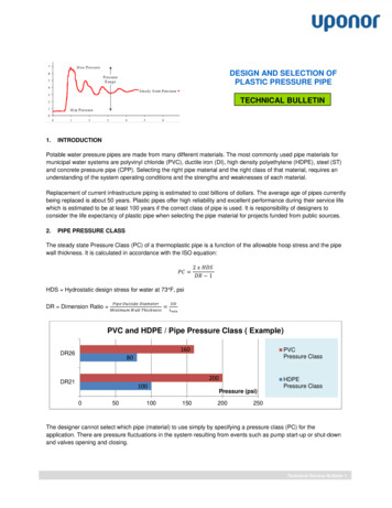
TABLE 1: ADHERED ASSEMBLIES OVER CONCRETE DECK (NEW OR EXISITNG)Adhered Assemblies over Concrete Deck (New or Existing)SystemNo.1234VaporBarrierBase Insulation LayerTop Insulation or Base PlyRoof CoverTypeFastenerAttach-Min. 1.5-inchthick, one ormore layers,ENRGY 3,ENRGY 3 AGF,ENRGY 3 CGF,ENRGY 3 tes(round orsquare)1 per1.78 ft²-Min. 1.5-inchthick, one ormore layers,ENRGY 3,ENRGY 3 AGF,ENRGY 3 CGF,ENRGY 3 FRanycombination-Simultaneouslysecuredwith toplayerMin. 0.25inchGypsumFiber are)Min. 1.5-inchthick, ENRGY3AllPurposeFastenersandUltraFastPlates(round orsquare)1 per1.33 ft²Min. 0.25inchGypsumFiber RoofBoardJM TwoPartUrethaneInsulationAdhesive12-inchocMin. 1.5-inchthick, one ormore layers,ENRGY 3,ENRGY 3AGF, ENRGY3 CGF,ENRGY 3 tes(round orsquare)1 per1.78 h toplayerTypeFastenerAttachType---JM PVCJM PVC MembraneAdhesive (Low VOC)applied 1.67 gal/100 ft²JM PVCJM PVC MembraneAdhesive (Low VOC)applied 1 - 1.1 gal/100 ft²JM FleeceBackedJM PVC MembraneAdhesive (Water Based)applied 0.8 – 1.2 gal/100ft²JM PVCJM PVC MembraneAdhesive (Low VOC)applied 1 - 1.1 gal/100 ft²JM FleeceBackedJM PVC MembraneAdhesive (Water Based)applied 0.8 – 1.2 gal/100ft²JM FleeceBackedASTM D312 Type IVAsphalt1 per1.33 ft²Page 11 of 39AttachMDP(psf)52.5FIRE RATINGUL790/ASTM 1:1252.5A2:12
TABLE 1: ADHERED ASSEMBLIES OVER CONCRETE DECK (NEW OR EXISITNG) (cont)Adhered Assemblies over Concrete Deck (New or Existing)SystemNo.VaporBarrier5Base Insulation LayerTypeMin. 1.5-inchthick, one ormore layers,ENRGY 3,ENRGY 3 AGF,ENRGY 3 CGF,ENRGY 3 FRanycombinationMin. 1.5-inchthick, one ormore layers,ENRGY 3,ENRGY 3 AGF,ENRGY 3 CGF,ENRGY 3 FRanycombination6-7(Optional)JM VaporBarrier SAappliedover deckprimedwith JM SAPrimer LowVOCMin. 1.5-inchthick, one ormore layers,ENRGY 3,ENRGY 3 AGF,ENRGY 3 CGF,ENRGY 3 FRanycombination-Min. 1.5-inchthick, one ormore layers,ENRGY 3,ENRGY 3 AGF,ENRGY 3 CGF,anycombination8Top Insulation or Base PlyFastenerAttach-Simultaneouslysecuredwith d orsquare)JMRoofingSystemUrethaneAdhesiveor JM ionAdhesiveor JM TwoPartUrethaneInsulationAdhesive1 per1.0 ft²12-inchoc12-inchocTypeMin. 0.25inchGypsumFiber RoofBoardMin. 0.25inchGypsumFiber RoofBoard,RetroPlus, orInvinsa,Invinsa FRRoof Board(Optional)Min. 0.25inchGypsumFiber RoofBoard,RetroPlus, orInvinsa,Invinsa FRRoof Board(Optional)Invinsa orInvinsa FRRoof BoardFastenerAttachTypeAttachMDP(psf)FIRE RATINGUL790/ASTM E108ClassMaximumInclineJM PVCJM PVC MembraneAdhesive (Low VOC)applied 1 - 1.1 gal/100 ft²JM FleeceBackedJM PVC MembraneAdhesive (Water Based)applied 0.8 – 1.2 gal/100ft²6-inchocJM FleeceBackedJM Roofing SystemUrethane Adhesive applied12-inch OC67.5A1/2:1212-inchocJM FleeceBackedJM Roofing SystemUrethane Adhesive applied12-inch OC67.5A1/2:12All PurposeFastenersandUltraFastPlates(square)1 per1.0 ft²JM RoofingSystemUrethaneAdhesiveor JM TwoPartUrethaneInsulationAdhesiveJM RoofingSystemUrethaneAdhesiveor JM ionAdhesive orJM TwoPartUrethaneInsulationAdhesiveRoof Cover1:1260.0A1:12JM PVC MembraneAdhesive (Water Based)applied 1 gal/100 ft²12-inchocPage 12 of 39JM FleeceBackedASTM D312 Type IVAsphalt1:12105.0A2:12
TABLE 1: ADHERED ASSEMBLIES OVER CONCRETE DECK (NEW OR EXISITNG) (cont)Adhered Assemblies over Concrete Deck (New or Existing)SystemNo.9VaporBarrier-10-11-1213--Base Insulation LayerTypeFastenerMin. 1.5-inchthick, one ormore layers,ENRGY 3,ENRGY 3 AGF,ENRGY 3 CGF,anycombinationJMUrethaneInsulationAdhesiveor JM TwoPartUrethaneInsulationAdhesiveMin. 1.5-inchthick, one ormore layers,ENRGY 3,ENRGY 3 AGF,ENRGY 3 CGF,anycombinationMin. 1.5-inchthick, one ormore layers,ENRGY 3,ENRGY 3 AGF,ENRGY 3 CGF,anycombination,min. 1-inchFesco, min.1.5-inch FescoFoam orRetro-FitMin. 1.5-inchthick, one ormore layers,ENRGY 3,ENRGY 3 AGF,ENRGY 3 MD312Type IVAsphaltTop Insulation or Base PlyAttach12-inchoc12-inchoc-Type(Optional)Invinsa orInvinsa FRRoof BoardInvinsa, orInvinsa FRRoof Board-FastenerJMUrethaneInsulationAdhesiveor JM ionAdhesiveRoof CoverAttach12-inchocTypeJM PVC12-inchocJM PVC-JM FleeceBacked-JM PVCJM ge 13 of 39AttachJM PVC MembraneAdhesive (Low VOC)applied 1.67 gal/100 ft²OrJM PVC MembraneAdhesive (Water Based)applied 0.67 gal/100 ft²JM PVC MembraneAdhesive (Low VOC)applied 0.83 gal/100 ft²OrJM PVC MembraneAdhesive (Water Based)applied 0.67 gal/100 ft²ASTM D312 Type IVAsphaltFIRE RATINGUL790/ASTM :12JM PVC MembraneAdhesive (Low VOC)applied 1.67 gal/100 ft²--MDP(psf)1:12217.5JM FleeceBackedASTM D312 Type IVAsphaltJM FleeceBackedJM PVC MembraneAdhesive (Water Based)applied 1.0 gal/100 ft²A2:12217.5A1:12
TABLE 2: Mechanically Fastened Assemblies over Concrete Deck (New or Existing)Base Insulation LayerSystem No.TypeAttach14Min. 1-inch thick,one or more layers,ENRGY 3, ENRGY 3AGF, ENRGY 3 CGF,ENRGY 3 FR anycombinationPrelim. Orwith top layerattached15Min. 1-inch thick,one or more layers,ENRGY 3, ENRGY 3AGF, ENRGY 3 CGF,ENRGY 3 FR anycombinationPrelim. Orwith top layerattached16Min. 1-inch thick,one or more layers,ENRGY 3, ENRGY 3AGF, ENRGY 3 CGF,ENRGY 3 FR anycombinationPrelim. Orwith top layerattached17Min. 1-inch thick,one or more layers,ENRGY 3, ENRGY 3AGF, ENRGY 3 CGF,ENRGY 3 FR anycombinationPrelim. Orwith top layerattached18Min. 1-inch thick,one or more layers,ENRGY 3, ENRGY 3AGF, ENRGY 3 CGF,ENRGY 3 FR anycombinationPrelim. Orwith top layerattached19Min. 1-inch thick,one or more layers,ENRGY 3, ENRGY 3AGF, ENRGY 3 CGF,ENRGY 3 FR anycombinationPrelim. orwith top layerattachedTop Insulation LayerType(Optional) Min.0.25-inchGypsum-FiberRoof Board,Invinsa, orInvinsa FR RoofBoard(Optional) Min.0.25-inchGypsum-FiberRoof Board,Invinsa, orInvinsa FR RoofBoard(Optional) Min.0.25-inchGypsum-FiberRoof Board,Invinsa, orInvinsa FR RoofBoard(Optional) Min.0.25-inchGypsum-FiberRoof Board,Invinsa, orInvinsa FR RoofBoard(Optional) Min.0.25-inchGypsum-FiberRoof Board,Invinsa, orInvinsa FR RoofBoard(Optional) Min.0.25-inchGypsum-FiberRoof Board,Invinsa, orInvinsa FR RoofBoardRoof CoverAttachPrelim.attachedPrelim.attachedFIRE RATINGUL790/ASTM E108MaximumClassInclineTypeAttachJM PVCExtra HL Fasteners & Plates 6inch OC within 6-inch wide lapsspaced 114-inch OC. Lapssealed with 1.5-in. heat weldoutside lap37.5A2:12JM PVCHL Fasteners & Plates 12-inchOC within 5-inch wide lapsspaced 73-inch OC. Lapssealed with 1.5-in. heat weldoutside lap45.0A2:12HL Fasteners & Plates 6-inchOC within 6-inch wide lapsspaced 114-inch OC. Lapssealed with 1.5 in. heat weldoutside lap45.0JM PVC SD PlusHL Fasteners & Plates 12-inchOC within 6-inch wide lapsspaced 54-inch OC. Lapssealed with 1.5-in. heat weldoutside lap45.0A2:12JM PVCHL Fasteners & Plates 6-inchOC within 6-inch wide lapsspaced 72-inch OC. Lapssealed with 1.5-in. heat weldoutside lap45.0A2:12JM PVC(Min.60 mil)HL Fasteners & Plates 12-inchOC within 5-inch wide lapsspaced 73-inch OC. Lapssealed with 1.5-in heat weldoutside lap52.5A2:12JM PVCPrelim.attachedJM Fleece .attachedPage 14 of 392:12A2:12
TABLE 2: Mechanically Fastened Assemblies over Concrete Deck (New or Existing) (cont)Base Insulation LayerSystem No.TypeAttach20Min. 1.5-inch thick,one or more layers,ENRGY 3, ENRGY 3AGF, ENRGY 3 CGF,ENRGY 3 FR anycombinationPrelim. orwith top layerattached21Min. 1.5-inch thick,one or more layers,ENRGY 3, ENRGY 3AGF, ENRGY 3 CGF,ENRGY 3 FR anycombinationPrelim. orwith top layerattached22Min. 1.5-inch thick,one or more layers,ENRGY 3, ENRGY 3AGF, ENRGY 3 CGF,ENRGY 3 FR anycombinati
Sub-level 2: 07 50 00 - Membrane Roofing Sub-level 3: 07 54 00 - Thermoplastic Membrane Roofing Sub-level 4: 07 54 19 - Polyvinyl-Chloride Roofing COMPANY: Johns Manville 717 17th St. Denver, CO 80202-3330 USA www.jm.com 1. SUBJECT: JM PVC 50 mil, JM PVC 60 mil, JM PVC 80 mil JM PVC Fleece Backed 50 mil, JM PVC Fleece Backed 60 mil,