Transcription
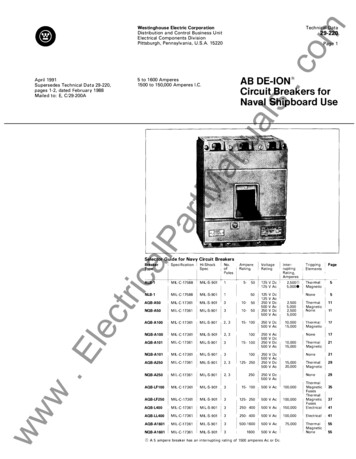
.comTech n i cal DataWestin ghouse Electric CorporationDistribution a nd Control B u si n ess U n itE l ectrical Components DivisionPittsb u rg h , Pen n sylva n i a , U . S . A. 1 522029-220Pag e 1AB DE-ION Circuit Breakers forNaval Shipboard Use5 to 1 600 Am peres1 500 to 1 50,000 Am peres I. C.lPartManualsApril 1 99 1S u persedes Tec h n ical D a t a 29-220,pages 1 -2, dated Feb r u a r y 1 988M a i l e d to: E, C/29-200AdcaSelector Guide for Navy Circuit L-C- 17588IHi-ShockSpecMIL·S-901IVoltageRatingNo.1 901310-50NQB-A50MI L-C-17361MIL-S-901310-50AQB-A100MIL-C-17361MI L-S-9012, 315- 100NQB-A100MIL-C-17361MIL-S-9012, 3100AQB-A101MI L-C-17361MIL-S-901315- 100100NQB-A101MIL-C-17361MIL-S-9013AQB-A250MI L-C-17361MI L-S-9012, 3125- 250NQB-A250MIL-C-17361MIL-S-9012, 3250L1TnppmgElementsI1Page TherMagneticV DeV AcV DeV AcV DeV Ac2.5005,0002,5005,000ThermalMagneticNone11250 V De500 V 0250500None511250500250500V AcV DeV DeV Ac10,00015,000ThermalMagnetic250500250500V DeV AcV DeV AcNone2115,00020,000ThermalMagnetic29None29250 V De500 V AcAQB-L400MIL-C- 17361MIL-S-9013250- 400500 V lectricalAQB-LL400MIL-C-17361MIL-S-9013250- 400500 V Ac100,000Electrical41AQB-A1601MI L-C-17361MIL-S-9013500-1600500 V Ac75,00055NQB-A1601MIL-C-17361MIL-S-90131600500 V 315- 100500 V Ac100,000AQB-LF250MI L-C-17361MIL-S-9013125- 250500 V Ac100,000CDA 5 ampere breaker has an interrupting rating of 1500 amperes Ac orDe.35374155
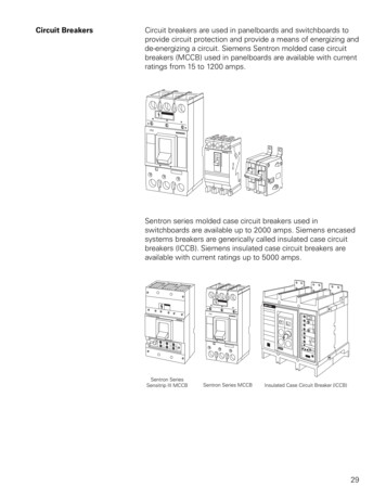
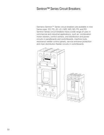
.comTech nical Data29-220Page 2ualsD es c r i p t i o nThese molded case Navy circuit breakersprovide both overload protection for con ductors a nd short circuit protecti o n for a l lcircuit elements such a s conductors, motorsand starters. They also serve as m a n u a l dis con necting means as well as circuit pro tectors.All Westing house c i rcuit breakers in thisTechnical Data meet a pplicable N avy spec ifications fo r "hi-sh ock". These m a n u a l l yoperated breakers a re rated f r o m 5 to 1 600a m peres with interrupting ratings from 1 ,500to 1 50,000 a m peres. ( See "selector g u i de"on p a g e o n e f o r r a t i n g s a n d N a v yspecifications.)anOperating HandleShown In--,;.,;- !--- Off PositiontMDesi g n FeaturesWesting house Navy circ u i t breakers retainall the features of sta ndard comm erc i a l typeA B De- ion breakers listed on the next pageunder "standard features." B u ilt to Navyspecifications, they i ncorporate the follow ing Navy requirements:Spe c i f i c N a vy F e a t u r e sFront view of assembled AOB-A250 Navy circuit breaker. Note that the shock resistant material (MAI-60)used for housing and cover is light gray.arR e s i s t a n t Mo l d e d C a se:Housing consists of rear base section a n dcover m o l ded of glass a l kyd mate r i a l . Thismaterial, reinforced g l a s s f i l led therm oset t i n g p l a st i c , h a s v e r y h i g h m e c h a n i c a lstrength ( shock a n d i m pact resistance), i sboth f i r e a n d m o istu re-resistant and pro vides exce l l ent d i e l ectric cha racteristics.lPG) Sh o c k@ A n t i -Sh o c k------- Terminal StudscaD e vi c e: I nertia weightover center pole holds trip bar i n latchedposition u n der shock conditions but doesnot prevent thermal or magnetic trip u n itsfrom fu ncti o n i n g on overload and shortcircu its.Block,----- MountingMounting StudsQ) C a l i b rated fo r 50'C: AlltriNavy break ers are c a l i brated for shi pboard i n stall ationat 50'C a m bient.@) Inte r c h a n g e a ble Tr i p U n it s : All ther ,----- TerminalMounting Block@ Plug -inlecm a l and magnetic trip u n its i n AQB circuitbreakers are encased i n sealed, self-con tained u n its that are i nterchangeable withother trip u n its of d ifferent ampere rati ngswithin the same frame size.CD.EC o n n ec t o rs: All AQB break ers are desig ned for easy plug - i n i nstal l a tion. P l u g - i n type connectors a r e built i ntothe base of the breaker for use with moldedmounting blocks complete with studs. Forfront connection, pressure-type cable ter minals are used i n stead of plu g - i n con nectors.@ ALB breakers have a clamp ter minal on the l i n e end to receive panelboardbus stab projections.I nterchangeable trip units are n o t available in the A 1 01,ALB-1 or A50.All A101 and A50 breakers have plug-in connectors.Front or rear connectors determined by mounting baseselected.wCDww ,---- Plug-In StudsL----Slip TypeConnectorsRear view of breaker showing terminal blocks for switchboard mounting. (Term inal block attached atline end of breaker and remo ved from load end.)Westing house E l ectric CorporationDistribution and Control Busi ness U n itE l ectrical Components DivisionPittsburgh, Pennsylva n i a , U . S .A. 1 5220April 1 991
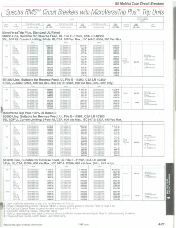
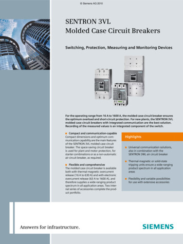
.comWestinghouse Electr ic Cor por ationD i stribution and Control Busi ness U n itE l ectrical Compone nts DivisionPittsbu rg h , Pennsylva n i a , U . S.A. 1 5220Standar d Featur esG) Corr osi o n - R es i stant:@ PositivePosi t i o n I n d icati o n : Posi tion of handle always ind icates ON, O F F, orT R I PPED.Bear i n g S ur faces: Dissi milarmetals are used to ·prevent bearing wear andelimi nate sticking.calPar@ De-ionA l l o y Co ntacts: Speci a l silveralloy contacts prevent sticking a n d weld i n g ,i ncrease contact l i f e and i nsure l o w resis tance when carrying f u l l - rated load.@ Quick- M ake,Arc ChuteRemovedtriQ u i c k - Br e a k O v erCenter Tog g l e M ec h a n i s m : Providesquick, positive action in opening and c l os ing of c i rc u its, prevents "teasi ng" of con tacts and reduces contact wear.AB DE-ION Circuit Breakers forNaval Shipboard UsetM@ Fr ee@ S i lverPa ge 3anAll parts arespecially treated to resist corrosion. Fung us moisture resistant treatments for severe at mospheres are available as modifications.Ar c Quencher s: This West ingho use development consists of a seriesof grid plates mounted in para llel betweensupports of i nsu lating materia l . The slots i nthe steel plates are directly over t h e contactsand draw the arc from the movi ng contactu p i nto the divided chamber where it is con fined, divided, and extingu ished.29-220uals5 to 1 600 Am peres1 500 to 1 50,000 Am peres I . C.April 1 99 1Supersedes Tech n i cal D a t a 29-220,pages 1 -2, dated October 1 978Mailed to : E, C/29-220ATechnical Data(j) C o m pl ete l nter po l e B arr i er s: I nsureinterna l@ Commonflas hoverswhenfau ltslecaga instoccur.Tr i p: Two and three-poleu n its have i nsulated common trip bar thatopens all poles simu ltaneously when a noverload occurs on a ny one, t h u s eliminat ing possibility of single- phasing.E TestedAccur acy: A l l tripping mem bers have g ro u n d a nd po l i shed latch s u r faces heat treated to prevent g a l l i n g or laterdistortion. A l l pa rts a re tested i n tempera tu re-control l ed atmosphere to assu re cor rect ca l i bration and p e rfect mati n g . Eachbreaker is thoro u g h l y tested.w@ FactorywwSealed: Smal ler breakers arefactory sealed to prevent tampering withcal ibration. I ntercha ngeable trip u n its areindivid ually sealed. -- MoldedOperatingHandleRemoved
.comTechnical Data29-220Page 4G en eral O r d e r i n g I n fo rmatio nWhen ordering Westing house N avy circuitbreakers, consult the check list below t om a ke sure y o u have provided correct infor mation. You should specify:ualsAppl icatio nDesigned primarily for circuit protection, Westi ng house N avy circuit breakers are used inl ig hting and power panels, switchboards, distribution centers and load centers aboardship. The photograph below i l l ustrates the use of molded case circuit breakers i n a typicalNavy switchboard.1 . Quantity, Westi n g ho use Pa rt N u m b e ra n d N ational Stock N u m be r of:a. Com plete breaker or frame, trip u n it,fuses (where required) and/or attachmentswhere ava i l able.b. Pl u g - i n mounting block or front con necting cable term inals.anc . Spare breakers or trip units. (usua lly onerequired for each ten u n its or fraction there of of each current rati n g . )d . Technical M a n u a ls.tM2 . S h i pment:S pecify transportation means, method ofpackaging and preservation, and requiredshipping date.4. I nspectio n :I n d i ca t e w h e t h e r G o v e r n m e n t S o u r c ei nspection i s requ i red at factory p r i o r toshi pment.ElectricalPar3 . Drawings:Specify quantity of outline or master plandrawings required.wwwWestinghouse E l ectric CorporationDistribution and Control B u s i ness U n itE l ectrical Compone nts DivisionPittsburgh, Pen nsylva nia, U,S.A. 1 5220April 1 991"""''
.comWestin ghouse Electric CorporationDistribution a n d Control B u s i n ess UnitE l ectrica l Com ponents D ivisionPittsburgh, Pennsylva n i a , U . S .A. 1 5220Technic a l Data29-220Page 5Types ALB- 1 , N LB- 1 , 1 2 5 Volts Ac a n d De,50 Am peres M a x i m u m , 5000 Am peres I. C.ALB-1 an d NLB-1 Breaker sSpecification: MIL-C-175885-50 Am peres, 60 or 400 Cyc l e1 2 5 Volts Ac or De S i ng l e PoleList Prices Refer to Price List 29-020Circuit Breakers- Net Weight: 8 oz.Ampere- l'l J!ir1[5101520253035405050TypetMarbreaker. Note clamptype stab terminal forpanelboard mount ing at line end andpressure type termi nal for front con nee·tion at load end.Moun tin g BasesTypecaIn terruptin g Ratin g1 0-50 Amp U n its : 5,000 Amps Ac a n d 2500Amps De5 Am p U n it: 1 , 500 Amps Ac o r DcSingle breaker, front panel supportedSingle breaker, surface mountedTwo breakers, front panel supportedDe, single phase0 and part (%) ofcombination for 3-phase@Part (213) of combination for 3-phaseapplication@3-phase panel application@)De, single phase0 and part (VJ) ofcombination for 3-phase@lectriH i g h s h ock N avy ALB-1 c i rc u it brea kers aredesigned for s h i pboa rd protection of s i n g l ephase Ac a n d D e c i rcu its o r th ree- phase Acc i rc u its when breakers a re c o n n ected by h a n d l e yokes fo r 2 a n d 3-po l e operat i o n .T h e N L B- 1 breaker is the non-automatic de sign of the ALB- 1 . S i nc e the tripping ele mentis om itted, it is used as a m a n u a l disc o n n ect.EN o n-adjustable thermal and magnetic tripelem ents a re factory c a l i brated a n d sealed.The tripping element i s counterba l a nced toreduce possi b i lity of acc identa I tripping u n dershock. All parts a re given a c o rrosion resistant treatment i n c o m p l i a nce withM I L- E-91 7 .wwwP l u g- i n l i n e c o n nections s i m p l ify panel boardmounting. A c l a m p type term i n a l o n the l i n eend of the breaker provides plug- i n c o n n ec tion to bus stabs in panel boa rd m o u ntingbloc ks . F o r front connection, there is a p res s u re type te r m i n a l o n the load end of thebreaker.NationalStock 65925-0 1 -01 7-301 15925-00-549-53595925-00-549-53605925-01 - 1 7 5-82045925-01 -261 -56255925-00-549-53655930-00-548-7068Special ALB-1 an d NLB- 1 BreakersS i m i l a r to a bove exc e pt to have a 1 A-1 B a u xi l i a ry switch rated 5 a m p resistive, 250 voltsAc o r 30 volts De max. ( N ot s u b m itted for Navy a p p rova l . and does not use brea ke r m o u nt i ng bases. ) O rder by desc ription.lPALB-1 Navy 454D507G09454D507G1 0anALB-1ALB-1ALB- 1ALB-1ALB-1ALB-1ALB- 1ALB-1ALB-1N LB-1 CDAB DE-ION Circuit Breakers forNaval Shipboard UseualsApril 1 99 1Supersedes Tec h n ic a l D a t a 29-220,pages 5-6, dated May 1 980M a i led to : E, C/29-200ATop view of typical ALB-1 panelboard mount ing base. (Style 4540509G04)NationalStock No.5925-01 454D509G045925-00-660-3562454D509G055925-00-201 -7 1 75454D509G065925-00-544-59805925-00-20 1 -7 1 76454D509G08. . . .Net Wt.in Lbs.'!.'!.'/,'h2/3'hIn dividual Reproduction s: When req u i red, reproductions of m a ster d rawings, outl i n e draw i n gs and certific ation sheets can be ordered as f o l l ows:Item1234[) escriptionFull size photolithic tracing of master drawing on vellumOutline and drilling plan on vellumCertification data on vellumReproductions of items 1, 2 or 3Drawin gs Available : Master drawing900J396; breaker outl i n e 3 1 4C 2 1 8; m o u ntingbases 455D791 a n d 369D592.Techn ical Man u al: N avships No. 362-2228.This booklet per M I L- M- 1 5071. When re q u i red, o rder BVR-TM-378.Han d le Y okes: Provide i nter l ocking of two or th ree one-pol e brea kers for s i m u ltaneous oper ation. I n di v i d u a l pole tripping is o bta i n e d without n o r m a l trip i n dicating (center) position.Poles23CD@Style N-- umber207B508H01207B508H02-- ------Tr1pp1ng element omitted for manual disconnect. Letter"N" hot stamped in white on handle.In De or single phase panel applications, basic patter ISone molded base accommodating four single-pole break ers. (See pages 7 and8.)@National Stock No.5925-00-202-09385925-00-296-8926In 3-phase application where bas1c pattern is threemolded bases, one 454D509G04 and two 454D509G05 arerequired, each base accommodating two breakers per cir @cuit {See page 7.)For 3-phase application where basic pattern is onemolded base accommodating up to six breakers or twobreakers per circuit (See pages8 and 9.)
.comTechnical Data29-220Page 6Outline Dimensions ALB-1 Breaker and M o u nting BasesBr eaker OutlineualsSingle Base, Fr ont P anel Suppor ted(454D509G0 1 ))0 Tr 1 pped?32 1 f- 32 32 3222.16J!:1622rl@ iiMountingslotAmpere Rot1ng 1 1,2-J-Standar d Br eakerlca.190-32 Top I 2 holes)1612 1 ---- ; l5I 41r 32 , z '-Il t - - .Steel plate.--554 thiCk--:!'-- 'tof1 .jMount1ngplateMounting of Fr ont P anel Suppor ted Bases (Side View)2-.190-32 X 3Breaker escutcheon and mountmg s crewsBasemounting screws7 32 32lecCrit1col dimens1ons ofstab and mount1ng clip3/ /withtri15153 f1 32!1-:' ttf 14 ffi JT 'r- tf tf .:'"2 Screws, steel, .190-32 X 3 furnishedlockwoshers for secunng to panel front coverzlSpecial Br eaker with Auxiliar y SwitchSingle Base Surface Mou nted (4540 509G02)- 3264 tMAmpere rot1ngIIarlTwo Br eaker Base, Fr ont P a nelSuppor ted (454D509G03)lPI 8an a-3 P ole Handle Yoke (207B508H02) - u:J-- --o t J]15.195 -- - 2 32-.23 4 n2 P ole Handle Yoke (207B508H0 1 )www.EMounting of Surface Mounted Base (Side View)Westinghouse E l ectric CorporationDistribution and Control Busi ness U n itE l ectrical Compone nts DivisionPitts b u rgh, Pennsylv a n i a , U . S.A. 1 5220Apr il 1 991
.comTech n ic a l DataWestinghouse Electric CorporationDistribution a n d Control Busi ness U n itElectric a l Components DivisionPittsburg h , Pennsylv a n i a , U . S . A. 1 5220April 1 99 1Supersedes Technic a l D a t a 29-220,pages 7-8, dated October 1 978M a i led to: E, C/29-200AAB DE-ION Circuit Breakers forNaval Shipboard UseualsABL-1 Breaker Mounting Bases, ContinuedBus Bar Drilling for De and 1 Phase Panels(Y. x 1 Copper Bus not Supplied)(2 Separate Bases shown. Basic Pattern i s1 Molded Base Acc om modatin g 4 Single Pole Breakers)Busbor CanStab BosePage 7Types A LB - 1 , N L B - 1 , 1 25 Volts Ac and De,5 0 Amperes Maximum, 5000 Amperes I . C.Application in De and 1 Phase PanelsBusbor AB usoor AartMBusborC29-220Front VrewPhase Panel ApplicationlP3For Two Breakers per load Circuit(Basic Pattern of Three Separate MouldedBases can be R epeated for Longer Panel Boards)Bu s bar AcaBus barB and stab baseBus Bar Drilling for3Phase PanelsFor Two Breakers per Load Circuit(Y.x1 Copper Bus not Supplied)4540509G057ibFront View 1ttriStab basemtg screws/.190 · 32 Toppedw.ElecStabbosemtgOutline Dimensions for Mounting Bases454D50 9 G 04 or 454D509 G 05, H01ameter 2 counter bores dee ww13 -- t1 2 j-- - --64 D1ameter 4- ------------- , cZ h o el s----- 16.3.iL------6*7- -- il-Front Vrewholes
Technical Data.com29-220Page 8Dimensions, Continued ALB-1 Breaker and Mounting BasesApplication in De and 1 Phase Panels(2 Separate Ba ses shown. Basic Pattern is1 Molded Base Accommodating 4 Single Pole B reakers)( x1 Copper B u s not S u pplied)35BusbarC "- Bus bar A. uals" Bus bar ABus Bar Drilling for De and 1 Phase Panels4540509G0864II316/4540509G08Stab baseand mounting2 2an.190-32LTapped holestM4540509G083Phase Panel ApplicationFor Two Breakers per load Circuit( B asic Pattern of Three Separate MoldedBases can be Repeated for longer P a nel B oards) arBus bar B and Stab base 4540509G05B usbar /1 32 1.--Phase PanelsLca1 323For Two Breakers per Load Circuit( x 1 Copper Bus not S u pplied) "454D509G05tri -- 454 D509G05ci:n .Elec Stab base an dlPBusbar CStab base andmounting screw / Bus Bar Drilling forhick steel6 T.190-32Thd.Side ViewOutline Dimensions for Mounting Bases (Side View)454D509G05or 454D509G08wwwp ' ,v - - -'1Outline Dimensions for Mounting Bases454D509G05 or 454D509G08R Dia. 2 holesApril 1 991
.com8Tech nical DataWestingh ouse Electric CorporationDistribution a n d Control B u s i n ess UnitElectrica l Components DivisionPittsburgh, Pen nsylva n i a , U . S .A . 1 5220A LB - 1 , N L B - 1 , 1 25 Volts Ac, De;50 A mperes Maximum, 5000 Amperes I . C.Apri l 1 99 1S u persedes Tech n i c a l D a t a 29-220,pages 9- 1 0, dated October 1 978M ai l ed to: E, C/29-200APage 9AB DE-ION Circuit Breakers forNaval Shipboard UseualsTypes29-220ALB-1 Breaker Mounting BasesB u s Bar D r i l l i n g fo r 3 P h ase P a nel A p p l icatio n(For One or Three Breakers per Load Circuit)For One or Three Breakers per Load Circuit(Y. x 1 Copper Bus not Supplied)tMan3 P hase P a nel Applicatio narStab baseand mtg.scewslPIII- ca454D509G06O u t l i n e D i mensio ns fo r Mo u nting Base454D509G062 32 31tl6473, oiameter 2holesv:""3-- atrir6 Dia meter 2 counter bores/ deeplec--r.38I2I4Front P a nel Cutout1 Diam eter megg erholes if required.EO ut l i n e o f Base ( S i d e View)454D509G04, 454D509G05,454D509G06, 454D509G08Fro n t Vi ewwHan dle p ivotww5- ---3i6For 1 three pole circuitFor 1 Single pol e c ircuit
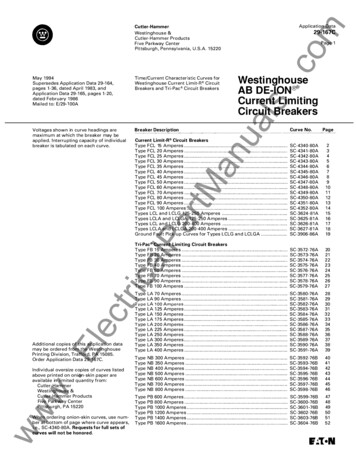
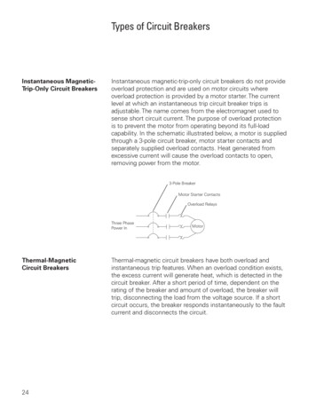
.comTechnical Data29-220Page 1 0Time Current Curve2I4020f---1Characteristic Time Current Curvef---1Instantaneous Tripping Occurs 320Amperes or 20 T 1mes Element Ratingf---1Whichever is Less . More Than050 Sec 800 Amperes Less Than .200Seconds\0\2\I I \0""' 0 '0in00.,4"'640uIa.;EE; .f\.Minimum//.'2""'2I4Times Rated Current56 7 8 9 1020C h a ract er i st i c Tempe rat u r e R at i ng C u rv e1101059590857570/100./90/eov10vv/// LoadType ALB-1lec10 0v50Ambient Temperature, Cso4030201090 100200300500l/ Connectiona Line1Drw OutStationary / C onn e c t1o nLoadType NLB-1o.EGo70triII530"""'Line120J.Wiring D i ag ra m12580""'I'I2MaximumtM"' I0ar'\.2u'"'uan\\I0lPlCharacteristic4ca MI L-C-1 7588This specification i ncludes the A L B - 1 typecircuit breaker. It req u i res that this breakercarry 1 1 5% of c u rrent ratings for more thanone hour and that the pri mary elements i n i tiate tripping at 1 38% rated c u rrent with i no n e h o u r a n d a t 200% i n 1 0 t o 1 00 seconds.A tripping c haracteristic of the primaryelement is based on the cu rrent flowingthrough all poles in series and in a n ambientof 50"C. The minimum i nstantaneous tripsetting shall be 320 amperes or 2 0 times theelement rati ng, whichever i s less, and tri pat not less than .050 second. At 800 a m peres t h e breaker must trip a t .200 secondor less.uals{C h a ract erist i c C u rves A L B - 1 BreakerCha ract er i st ic T i m e - C u r re nt C u rvewwwWest i n g h ouse E l ectric CorporationDistribution a n d Control B u si n ess U n itE l ectrical Com ponents DivisionPittsburgh, Penn sy lvania, U . S .A. 1 5220April 1 991
West ingh ouse Elect ric Corporat ionDistribution a n d Control Busi ness U n i tE l ectric a l Components DivisionPittsbu rg h , Pen nsylva n i a , U. S .A. 1 522029-220Page 1 1AB DE-ION Circuit Breakers forNaval Shipboard UseualsAOB-A50, N OB-A50, 500 V Ac, 250 V De50 Amperes M a x i m u m , 5000 Am peres Ac,2500 Am peres De \ . C.comApril 1 99 1N e w I nformationM a i led to: E, C/29-200ATec h n ic a l DataAOB-A50 and NQB-A50 BreakersanSpecificat ion: MI L-C- 173611 0-50 Amperes, 60 and 400 Cyc l e500 Volts Ac and 250 Volts De3 PoletMI nt errupt ing Rat ing5000 Amperes Ac and 2500 Am peres DeNon-I nterc h a ngeable trip u n itClass H i -S h oc k M I L-S-90 1 , 50 C a m bientlPcaThe N O B -A50 b r e a k e r i s a n o n- a u t o m a t icdesign of the AOB-A50. S i nce the tripping e l e ments a re o m itted, it is used as a m a n u a l dis c o n n ect. T h e N O B -A50 h a s a m a x i m u mconti nuous c u rrent rating of 50 a m peres.arThe AOB-A50 is a factory c a l i brated non adjusta ble thermal m a g n etic c i rcuit breaker.The c i rcuit breaker i s assembled as a th reepole device with c i rc u it protecting trip ele ments i n the two outside pol es. The unit c a nb e i n sta l l ed i n 2 p o l e a p p l ications b y con necting the 2 w i re c i rcuit to the outside pro tected poles.List P rice See Price List 29-020T rip Un itRatingSt y leNumberNational StockNumber60 6955925-00-783-66355925-00-797-9696400 C52G101244C52G 1 11244C52G 5925-00-948-3296www.ElectriType Gl Refer to Westinghouse for De Part Numbers and Information.Q) Complete breaker does not include mounting bases. Type requi red must be ordered separately. Mounting basesinclude cable lugs.0 Onlypole breakers furnished; for 2 pole application make connections to outside poles.3
Tech nical Data.com29-220Page 1 2StyleNumberNational StockNumberSingle Base- Line and Load Stabs, Front ConnectedSingle Base- Line and Load Stabs, Rear ConnectedSingle Base- Line Rear, Load Front ConnectedDouble Base Assembly- Line, Bus Connected; Load, Front ConnectedHandle LockHandle BootTechnical Manual1244C44G011244C44G021244C44G031244C45G0 15080A95H0 0055925-00-270-40065925-01-246-05695925-01-09 1 -9432Net Weigh t - Lbs.AOB-A50- 2.2N OB-A50- 1 . 9anS i n g l e Mounting Base- 0.7Double M o u nting Base- 1 . 5Handle Lock- .03ualsPanelboard Mounting and AccessoriesTypeAQB-A50Single MountingBase- Rear ConnectedSingle BaseLine StabsRear Connected;Load Stabs FrontConnected.ElectricalPAQB-A50Single MountingBase - Front ConnectedartMOrdering Information : See Page 4HandleLockDouble MountingBase- Front ConnectedwwwWesti nghouse E l ectric CorporationDistribution a n d Control Busi ness U nitE l ectrical Components DivisionPittsburgh, Pennsylva n i a , U . S .A . 1 5220April 1 991
Apr i l 1 99 1N e w InformationMai led to : E , C/29-200AOutline Dimensions AOB- A50 a n d NOB-A50 Breakers (Dimensions in I nches)INSERTS IN COVER (21 12-24 THDS3388""","""""'" 1 I lPcatri'----'RIIII1'13?[OF CLIP}2 2jrr r; : J !i4;2 85OFCLIPLOAD ENDILINELINE,2.6.EIIIIFIt;1Side View1;lec55AB DE-ION Circuit Breakers forNaval Shipboard Use11 1 111 1 1 1-OFFFront ViewPage 1 3;tM3ar429-220anBREAKER MOUNTING HOLESTWO #12-24 MOUNTiNG SCREWS4 1/8 LONG SUPPLIED WITH BREAKERTechnical DataualsAQB-A50, N QB-A50, 500 V Ac, 250 V De50 Am peres M a x i m u m , 5000 Am peres Ac,2500 Am peres De I . C .comWestingh ouse Electric CorporationDistribution and Control Busi ness UnitE l ectrical Compon ents DivisionPittsbu rgh, Pennsylva nia, U .S .A. 1 5220LOADLOADTYPE AQB-A50TYPE NQB-A50wwwWiring Diagram5,,DIA FOR INSULATION TESTFront Panel Cutout
.comTechnical Data29-220Page 1 4ualsSingle Base Un its (Dimensions i n I nches)tMan2964line and Load Stabs Back ConnectedcalPline and Load Stabs Front ConnectedWIRE CONNECTIONarWIRE CONNECTION.Electri10-32THDS.WIRE CONNECTIONline Stabs Back Connected, Load Stabs Front ConnectedwwwWesting house E l ectric CorporationDistribution a n d Contro l Busi ness U n itE l ectrical Components DivisionPittsburgh, Pennsylva nia, U . S.A. 1 5220April 1 99 1
.comWestingh ouse Electric CorporationDistribution a n d Control B u s i n ess UnitE l ectrical Compon ents DivisionPittsburgh, Pennsylva n i a , U . S.A. 1 522029-220Page 1 5AB DE-ION Circuit Breakers forNaval Shipboard UseualsAQB-A50, N QB-A50, 500 V Ac, 250 V De50 Amperes Maxim u m , 5000 Am peres Ac,2500 Am peres De I .C.April 1 99 1N e w InformationMai led to : E, C/29-200ATechnical Data'tOF CIRCUITBREAKERSLOADtMLINEanDouble Base Assembly (Panelboard) (Dimensions in I nch es)1 2lPar2,;;16LINEwww.ElectricaI32r----- 1""L jLine Bus Connected, Load Front Connected#10-32THREAD
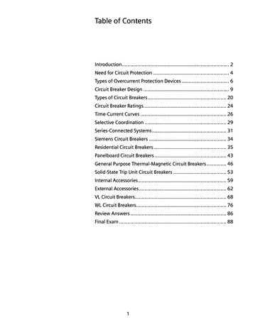
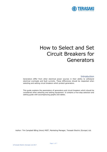
Technical Data.com29-220Page 1 6Navy Type AQB-A50Circuit Breaker00N;:\1000500300200r.n0z0uwr.n w:;503020Ng'"oooooo"""'0002g0N0 oo0 oo0 oo0 oo"" "''"00000100005000 -03000 2000:Ig 0 0000, "'1\).---\i 100tM r"00503020Maximum Trip Time10ar100000"'ualsPERCENT RATED CURRENT'\.lP\cav' Minimum Trip Timetri0 050030.0201.31\1\0 050 030.02I\lec.E0"'0200N0 0000""g"'000:;·'"c.:;·c"'01) 0050030020050030020014'000N0 0000'" .q- 1.1)gg0002PERCENT RATED CURRENT0000N0 oo0 oo0 oo0C)ciO"" "'00000100Time-Current Curves for AOB-A50 Circuit Breaker (60Hz, 400Hz and dc-10, 1 5, 20, 25, 30, 35, 40 and 50Ampere Ratings)wwwWesting house E l ectric Corpo rationDistribution and Control Bu siness U n i tE l ectrical Compon ents DivisionPittsburgh, Pennsylva nia, U . S .A. 1 5220April 1 991
I nterr u pti n g R at i n g1 5,000 Amps A c a n d 1 0,000 Amps DeualsThose breakers (and i nterrupte rs) desi g n edfor De motor ci rcuits a n d fo r Ac feeder c i r cuits (designated with a "BF" in a m p rat i n gco l u m n of price table) h a v e fixed i n stanta neous settings of 600%-700% cont i n u o u scu rrent ratings. Those h a v i n g a mag netice l em e nt set to trip at 1 200%-1 400% a reapplied on Ac moto r ci rcuits (designatedwith a "B"). Breakers desi g n ated with "BE"are calib rated for De appl icati o n .List P rices See Price List 29-020'1 764176417641 7641 7641 7641 7641 7646816826836846856866876881 051753505257001 7641 764176417641 764901 051 802101 501753003503003506007004505259001 0506007001 2001 400Non-Auto matic1 7641 7641 7641 76417641 7641 7641 7641 7641 7641 7641 05175350525700Two-Pole, 500 Volts AcThree-Pole, 250 Volts901 50300450600De.E1 5-BE25-BE50-BE75-BE1 00-BEThree-Pole, 500 Volts Acwww1 5-BF1 5-B25-BF25-B50-BF50-B75-BF75-B1 00-BF1 00-B1 00 .638638638638638. .5925-00-396-2283. . . . . . . . . . . . . . . . . . . . . . . . . . . . . . . .176417641 7641 7641 7641 7641 7641 764638638638638638638638638. . . . . . . . .689690691692693.5925-00-399-81 20. . .5925-00-399-81 2717641 7641 7641 7641 7646946956966976986997007017027037045925-00-1 1 3-5066. . . . . . 925-00-396-2339. . . . . . . . .5925-00-396-2345. . . . . . .5925-00-450-62755930-00-259-94401 764176417641 7641 7641 7641 7641 7641 7641 7641764. . . . . . . .5925-0 1 -221-1 765. . . . . . . .'.''.Trip Unit OnlyStyleNationalNumberStock No. . . . . . . . .1 7641 7641 7641 7641 764lec901 051 802101 501753003506007009001 0501 2001 400Non-Automatic1 7641 7641 7641 7641 764Breaker Frame OnlyCDNationalStyleNumberStock No.caDe676677678679680901 503004506001 5-BF1 5-B25-BF25-B50-B75-B1 00-B1 00 Co m plete Breaker(])NationalStyleStock No.Numbertri1 5-BE25-BE50-BE75-BE1 00-BEAOB-A100lPAQB -A 1 00 circuit breakers are designed foruse in lighting and distribution panel boardsand switchboards for the protection of feed er and motor branch circuits.Trip u n its with cu rrent rati ngs of 1 5, 25, 50,75 and 1 00 can be q u i ckly i nterc hangedand a conversion kit is available to changea 3 - pole, 500 volt AQB-A 1 00 to a non automatic N Q B - A1 00 circuit i nterrupter.N Q B - A 1 00 breakers have a maximum con tinuous current rati n g of 1 00 amperes, butthey are used only as disconnects si ncethere is no a u tomatic opening device.anSpecificat i o n : MI L-C-173611 5-1 00 Amperes500 Volts Ac and 250 Volts DeTwo or Three- PoleAB DE-ION Circuit Breakers forNaval Shipboard UsetMNote: AQB-A100 and NQB-100 breakers aresold for replacement only . Th ey are nolonger on Navy Qualified P roduct List.Two-Pole, 250 VoltsPage 17arA Q B - A1 00 andN Q B - A 1 00 B reakersI nsta nta neo usTrip Settingin AmperesLowHigh29-220Types AQB-A1 00, N Q B -A1 00, 250 Volts De,500 Volts Ac, 1 00 Am peres Maximum,1 5,000 Amperes I . C .April 1 99 1S u persedes Technical Data 29-220,pages 1 1 -1 2, dated Octo ber 1 978Mai led to: E , C/29-200ACont.AmpereRating.com8Technical DataWestingh ouse Electric CorporationDistribution a n d Control B u s i n ess U n itE l ectrical Com ponents DivisionPittsburgh, Pennsylv a n i a , U . S.A. 1 5220176417641 7641 7641 764640641642643644. . . . . . .5925-00-248-1 1 04. .5925-00-248-1 1 08. . . . . .645646647648649650651652. . . . . . .1 7641 7641764176417641 7641 7641 764. .5925-00-629-0975.5925-00-628-06955925-00-248-1 0785925-00-248-1 925-00-258-29451 7641 7641 7641 7641 7646536546556566575925-00-608-0972592
NQB-A100 MIL-C-17361 AQB-A101 MIL-C-17361 NQB-A101 MIL-C-17361 AQB-A250 MIL-C-17361 NQB-A250 MIL-C-17361 AQB-LF100 MIL-C-17361 . Westinghouse Navy circuit breakers are used in lighting and power panels, switchboards, distribution centers and load centers aboard ship. The photograph below illustrates the use of molded case circuit breakers in .