Transcription
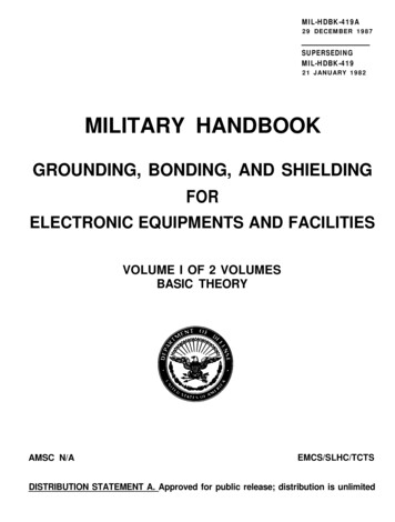
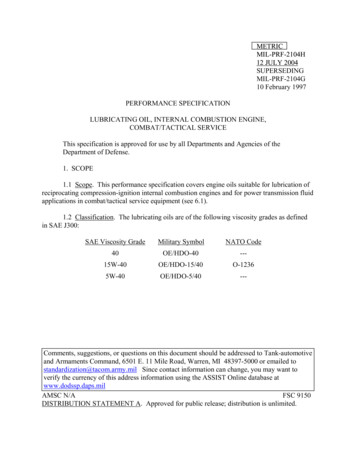
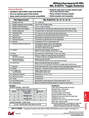
Military/Aerospace/HI-RELMIL-S-83731 Toggle SwitchesFeatures/Benefits Qualified to MIL-S-83731 Cage Code 63HW9 50 µ inch selective gold contact plating Epoxy sealed terminals for process compatibilityTest Requirement1. Strength of Terminal Rated for logic level to 5 amp resistive loadsand 2 amp inductive loads Flame retardant housing material RoHS compliant and compatibleMIL-S-83731/9, 10, 13, 14, 15, 161 lb. – solder lug2. Strength of Actuating Lever Pivot and Stop10 lbs. & 8 lbs. throughout range3. Strength of Mounting Means15 lbs. in. torque on bushing4. Dielectric (Sea Level) Indication1000 VAC Group B, 750 VAC after electrical endurance. 500 µA max. leakage5. Contact Voltage Drop2.5 millivolt initial, 5.0 millivolt after mechanical endurance @ 2-6 VDC 0.1 amp6. Temperature Rise50 C rise max. @ rated resistive load after endurance test7. Short Circuit10 operations carry 100 amps resistive load @ lowest DC volts8. Mechanical Life20K operations at specified high and low temperatures9. Electrical Endurance10K operations at specified high and low temperatures10. Overload50 operations @ 150% of rated resistive load11. Electrical Endurance at Sea Level10K operations resistive load @ room temperature10K operations inductive load @ room temperature10K operations lamp load @ room temperaturePerformed on different test samples12. VibrationMethod 204 of MIL-STD-202, test condition A.06 D. A. or 10 G’s 10-500 Hz, 10 usec. max. chatter13. ShockFuse-method 213 or MIL-STD-202, 10 usec. max. chatter14. Salt SprayTest Upon Completion48 hours – method 101 of MIL-STD-202, test condition B10 operations resistive load (toggle sealed switches only)15. Moisture ResistanceTest Upon CompletionMethod 106 of MIL-STD-202100 VDC potential between current carrying parts and panel16. Sand & DustMethod 110 of MIL-STD-202, test condition B6 hours @ 23 C 2.5K operations mechanical life (toggle sealed switches only)17. ExplosionMIL-STD-202 method 109, maximum rated DC inductive load (toggle sealed switches only)18. SealingToggle seal – 5 operations under 0.5 inches of H2O above top of bushing19. A.) Toggle SealB.) Bushing Seal(Toggle sealed switches only)(Panel sealed switches only)20. Temperature OperationMechanical life, –25 C to 71 C21. Life Low Cur. LevelNo requirement22. FungusNo requirement23. Intermediate Current20K operations, 35/40 milliamps @ 5 VDC resistive load @ 71 C24. Thermal ShockMethod 107 of MIL-STD-202 test condition A; 5 cycles @ –55 C/ 85 C RATINGSMATERIALSCURRENT RATINGS – HIGH LEVELCurrent Capacity in Amperes – Per Pole28V dc152115V ac, 400 HzLamp Load1Resistive Load5Inductive Load2125V ac, 60Hz152CURRENT RATINGS – LOGIC LEVEL0.5 Volt – Amp (VA) Max. @ 28 V Max. (AC or DC)HOW TO ORDER: Complete part numbers for MIL-S-83731 TOGGLE SWITCHES are shown on pages F–18 through F–21.Dimensions are shown: Inches (mm)Specifications and dimensions subject to change10 jan 20F–17www.ckswitches.comFToggleCASE: Diallyl phthalate (DAP) (UL 94 V-0).BUSHING: Brass, nickel plated.HOUSING: Stainless steel.ACTUATOR: Brass, chrome plated.SWITCH SUPPORT: Brass, tin plated.TERMINALS: Gold over nickel over copper alloy.TERMINAL SEAL: Epoxy.CONTACTS: Gold over nickel over silver over brass.PANEL SEAL: Silicone rubber.MOUNTING HARDWARE: Two hexagon nut, brass withnickel plating; one lockwasher, steel with nickelplating; one locking ring, brass with nickel plating.
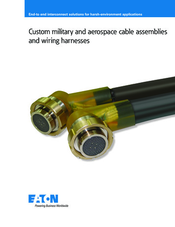
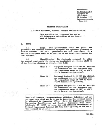
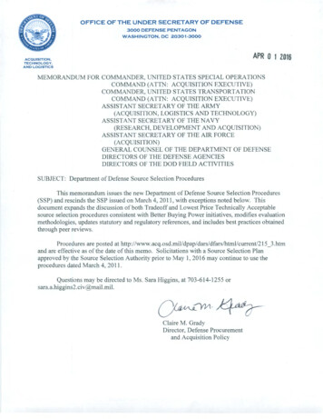
Military/Aerospace/HI-RELMIL-S-83731 Toggle SwitchesSWITCH FUNCTIONPOS. 1NO.POLESCONNECTED TERMINALSPOS. 3POS. 1POS. 2POS. 3SCHEMATICMODEL NO.M83731/9-211M83731/9-231SPPOS. MOM.OPENN/A2-3232-121OPENN/ASPDT2-32-1SPDTSWITCH FUNCTIONPOS. 1NO.POLESCONNECTED TERMINALSPOS. 3POS. 1POS. 2POS. 3SCHEMATICMODEL 0-271DPPOS. M.ONOFFMOM.ONONONONONMOM.OPENN/A2-3,5-623,5 62-1,5-421,5 DPDTPANEL MOUNTINGToggleFWithout locking ring.With standard locking ring.Dimensions are shown: Inches (mm)Specifications and dimensions subject to change10 jan 20F–18www.ckswitches.com
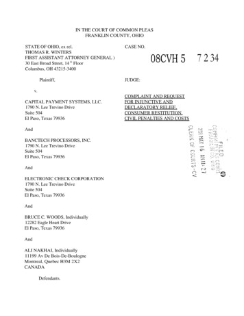
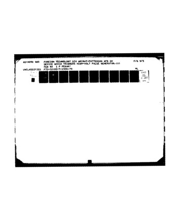
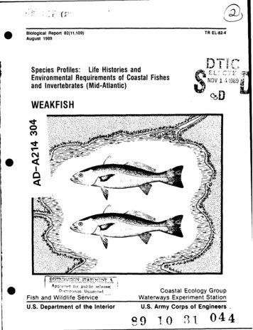
Military/Aerospace/HI-RELMIL-S-83731 Toggle SwitchesSWITCH FUNCTIONPOS. 1NO.POLESCONNECTED TERMINALSPOS. 3POS. 1POS. 2POS. 3SCHEMATICMODEL NO.M83731/9-212M83731/9-232SPPOS. MOM.OPENN/A2-3232-121OPENN/A2-3SPDT2-1PC MOUNTINGSPDTSWITCH FUNCTIONPOS. 1NO.POLESPOS. 3POS. 1POS. 2POS. 3SCHEMATICMODEL 0-272DPPOS. 2CONNECTED /A2-3,5-623,5 -3,5-62-1,5-4MOM.2-3,5-62-3,5-42-1,5-4DPDTPC MOUNTINGFToggleDPDTDimensions are shown: Inches (mm)Specifications and dimensions subject to change10 jan 20F–19www.ckswitches.com
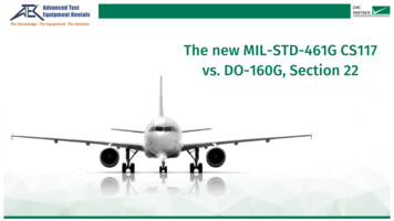
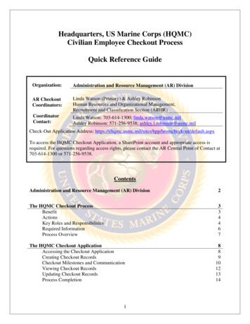
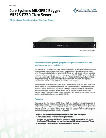
Military/Aerospace/HI-RELMIL-S-83731 Toggle SwitchesSWITCH FUNCTIONPOS. 1NO.POLESPOS. 3POS. 1POS. 2POS. 3SCHEMATICMODEL NO.M83731/13-211M83731/13-231SPPOS. 2CONNECTED PC MOUNTINGSPDTSWITCH FUNCTIONPOS. 1NO.POLESPOS. 3CONNECTED TERMINALSPOS. 1POS. 2POS. 3SCHEMATICMODEL 4-271DPPOS. M.ONOFFMOM.ONONONONONMOM.NONEONMOM.ONOPEN2-3,5-62 3,5 6N/A2-1,5-42 1,5 -62-1,5-4MOM.2-3,5-62-3,5-42-1,5-4DPDTPC MOUNTINGToggleFDPDTDimensions are shown: Inches (mm)Specifications and dimensions subject to change10 jan 20F–20www.ckswitches.com
Military/Aerospace/HI-RELMIL-S-83731 Toggle SwitchesSWITCH FUNCTIONPOS. 1NO.POLESPOS. 3CONNECTED TERMINALSPOS. 1POS. 2POS. 3SCHEMATICMODEL NO.M83731/15-211M83731/15-231SPPOS. NEONMOM.OPENN/A2-3232-121OPENN/A2-3SPDT2-1PC MOUNTINGSPDTSWITCH FUNCTIONPOS. 1NO.POLESPOS. 3POS. 1POS. 2POS. 3SCHEMATICMODEL 6-271DPPOS. 2CONNECTED OM.OFFMOM.ONOFFMOM.ONONONONONMOM.OPENN/A2-3,5-62 3,5 DPDTPC MOUNTINGFToggleDPDTDimensions are shown: Inches (mm)Specifications and dimensions subject to change10 jan 20F–21www.ckswitches.com
Vibration Method 204 of MIL-STD-202, test condition A.06 D. A. or 10 G’s 10-500 Hz, 10 usec. max. chatter 13. Shock Fuse-method 213 or MIL-STD-202, 10 usec. max. chatter 14. Salt Spray Test Upon Completion 48 hours – method 101 of MIL-STD-202, test condition B 10 operations resistive load (toggle sealed switches only) 15. Moisture Resistance Test Upon Completion Method 106 of MIL-STD-202 .